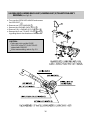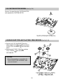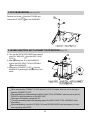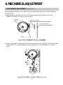
1
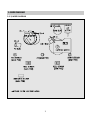
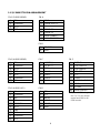
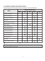
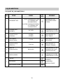
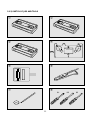
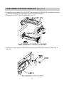
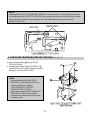
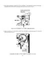
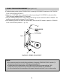
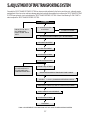
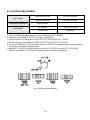
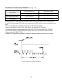
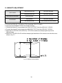
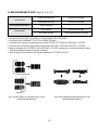
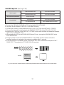
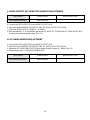
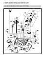
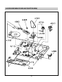
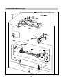
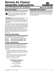
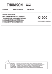
S/M No. : K3050MECHA
Service Manual
VCR MECHANISM UNIT
(K50 / K30-MECHA DECK)
DAEWOO ELECTRONICS CO., LTD.
http : //svc.dwe.co.kr
March. 2000
CONTENTS
1. MECHANISM DESCRIPTION .................................................................................................2
2. ASSEMBLY DIAGRAM & MAJOR PARTS CHECK ..............................................................5
3. DISASSEMBLY AND REPLACEMENT ................................................................................12
4. MECHANICAL ADJUSTMENT..............................................................................................22
5. ADJUSTMENT OF TAPE TRANSPORTING SYSTEM.......................................................27
6. EXPLODED VIEW AND PARTS LIST....................................................................................37
1
1.DESCRIPTIONOFTHEMECHANISM
1-1 CHARACTERISTIC OF THE K30-DECK MECHANISM
1) K30-MECHA DECK follows the VHS standard.
2) K30-MECHA DECK uses three motors (DRUM MOTOR, CAPSTAN MOTOR and L/C MOTOR)
3) K30-MECHA DECK uses L/C MOTOR to drive FRONT LOADING.
4) K30-MECHA DECK recognizes each mode by using a 4-BIT MODE signal. This 4-BIT MODE signal is
generated by the CAM SWITCH which is driven by the L/C MOTOR.
5) K30-MECHA DECK is operated by 7 MODES (EJECT/INITIAL/REV/IDLE/PLAY, STOP,
SLOW/BRAKE/FF & REW).
6) K30-MECHA DECK reduces the mode shifting time, that is, picture playing time by using the FULL
LOADING SYSTEM that has the DRUM wrapped by the tape.
7) K30-MECHA DECK is seperated from the Main PCB. When assembling, it is connected by B-B TYPE
CONNECTOR.
The CAPSTAN MOTOR and DRUM OUTPUT of K30-MECHA DECK and the MAIN PCB DECK are
directly connected without using cable.
2
1-2 WIRE DIAGRAM
1-2-1) WIRE DIAGRAM
3
1-2-2) CONNECTOR PIN ARRANGEMENT
CN-1 (2 HEAD MONO)
CN-A
1
SP-L
1
GND
2
COMMON
2
DRUM SPD CTL
3
SP-R
3
Vcc
4
GND
4
DRUM FG
5
DRUM PG
6
NON CONNECT
7
NON CONNECT
CN-B
CN-1 (4 HEAD MONO)
1
FE HEAD
2
GND
CN-C
CN-2
1
SP-L
1
L/C MT (+)
1
EVER 5V
2
COMMON
2
L/C MT (–)
2
CAPSTAN F/R
3
SP-R
3
GND
3
CAPSTAN FG
4
GND
4
CAM D
4
CTL-REF
5
EP-R
5
CAM C
5
CTL
6
COMMON
6
CAM B
6
I-LIMIT
7
EP-L
7
CAM A
7
CAPSTAN M/T 12V/18V
8
GND
9
IC GND
10
NON CONTACT
CN-1 (4 HEAD HI-FI)
CN-D
1
A-L
1
CTL
2
COMMON
2
CTL
3
A-R
3
AUDIO
4
SP-L
4
AUDIO
5
COMMON
5
ERASE
6
SP-R
6
GND
7
GND
8
EP-R
9
COMMON
10
EP-L
4
❉ Capstan M/T Voltage of
No.7 is 12V for normal
model and 18V for HIREW model.
2.ASSEMBLYDIAGRAM&MAJORPARTSCHECK
2-1. ASSEMBLING DIAGRAM
2-1-1) ASSEMBLING DIAGRAM OF DECK ASS'Y
A. TOP VIEW
8
9
7
6
5
!
4
@
3
#
2
$
%
^
&
*
(
1. FE HEAD
2. S SLANT POLE ASS'Y
3. TENSION BAND ASS'Y
4. REEL TABLE
5. MAIN BASE ASS'Y
6. RECORD SAFETY LEVER
7. S SUB BRAKE ASS'Y
8. S MAIN BRAKE ASS'Y
9. IDLER PLATE TOTAL ASS'Y
10. T MAIN BRAKE ASS'Y
)
1
11. T-SUB BRAKE ASS'Y
12. RELAY LEVER
13. CAPSTAN MOTOR
14. PINCH LEVER TOTAL ASS'Y
15. L/C BRKT TOTAL ASS'Y
16. CAM GEAR
17. A/C HEAD TOTAL ASS'Y
18. T SLANT POLE ASS'Y
19. DRUM TOTAL ASS'Y
5
B. BOTTOM VIEW
1. CAPSTAN MOTOR
2. F/L RACK
3. CONNECT PLATE
4. REEL BELT
5. REEL GEAR TOTAL ASS'Y
6. RECORD SAFETY LEVER
7. L LOADING ASS'Y
8. R LOADING ASS'Y
9. DRUM TOTAL ASS'Y
10. LOADING RACK ASS'Y
6
2-1-2) PARTS LOCATION OF FRONT LOADING ASS'Y
A. TOP VIEW
B. FRONT VIEW
7
2-2. PERIODIC MAINTENANCE AND SERVICE SCHEDULE
2-2-1) PERIODIC MAINTENANCE AND SERVICE SCHEDULE
A. In order to effectively maintain the excellent performance and fully utilize the features of this apparatus,
and to lengthen the life of the mechanism and tapes, we strongly urge you to perform periodic
maintenance and inspection, as described below.
After repairing, do the maintenance described below, irrespective of the length of time in use.
B. Cleaning of the Head Drum Ass'y
Clean the Drum assembly with a cleaning cloth soaked in liquid cleaner (alcohol) by placing lightly
against the Drum and slowly revolving the rotating HEAD DRUM Ass'y by hand (Do not rotate the
upper Drum by applying electric power to the motor when cleaning).
Do not move the cleaning cloth in the vertical direction against the heat-tip.
C. Cleaning the tape transporting section.
Clean the tape transporting parts with a cleaning cloth soaked in alcohol.
D. Cleaning of driving section
Clean the driving section with a cloth soaked in alcohol.
E. Routine inspection
Perform maintenance and inspection as separately described depending on the period of time in
use.
Refer to the table of 2-2-3.
2-2-2) CLEANING AND LUBRICATION
A. Cleaning of Tape Transporting section and Driving section
a. Cleaning of Tape Transporting section
The following parts should be cleaned after every 500 hours of use.
TENSION POLE
S SLANT POLE
AC HEAD/AE HEAD
S GUIDE POST
VIDEO HEAD/DRUM
T GUIDE POST
FE HEAD
T SLANT POLE
CAPSTAN SHAFT
S GUIDE ROLLER
T GUIDE ROLLER
PINCH ROLLER
VERTICAL POST
As the above parts contact with the video tape, they tend to collect dust particles. If they are stained
with dust or foreign substance it has a bad effect on the picture and may lead to damage of the tape.
After cleaning with alcohol, allow the parts to dry thoroughly before using a cassette tape.
b. Cleaning of Driving section
REEL TABLE
CAPSTAN FLYWHEEL/PULLEY
REEL PULLEY
B. LUBRICATION
S REEL POST
T REEL TABLE POST
REEL GEAR POST
After cleaning these parts with alcohol, lubricate these with one or two drops of oil.
8
2-2-3) SERVICE SCHEDULE FOR THE MAJOR PARTS
The following parts should receive periodic service, according to the recommended intervals.
PERIODIC SERVICE (TIME)
NAME
DRUM TOTAL ASS'Y
1000
2000
3000
4000
5000
¡
¡
¡
¡
¡
CAPSTAN MOTOR
¡
L/C BRKT TOTAL ASS'Y
REEL BELT
IDLER PLATE TOTAL ASS'Y
REEL TABLE
T SUB BRAKE ASS'Y
TENSION BAND ASS'Y
S MAIN BRAKE ASS'Y
T MAIN BRAKE ASS'Y
PINCH ROLLER ASS'Y
AC HEAD ASS'Y
FE HEAD
REEL GEAR TOTAL ASS'Y
: Check and Replace if necessary.
: Replace
Note: Even though the unit is not used frequently, cleaning, lubrication and replacement of the belt
should be undertaken every 2 years.
9
2-3. JIGS AND TOOLS
2-3-1) LIST OF JIGS AND TOOLS
ITEMS
1
ALIGNMENT TAPE
2
CLEANING TAPE
(DAEWOO)
DHC-602V
CHECKING OF THE TAPE
TRANSPORTING SYSTEM
3
CASSETTE TAPE
(KOKUSAI)
KT-300NV
KT-300RV
MEASUREMENT OF
REEL TORQUE
4
VHS SPINDLE
HEIGHT GAUGE
TSH-V4
MEASUREMENT OF
REEL HEIGHT
5
TENTELO METER
(TENTELO)
T2-H7-UM
MEASUREMENT OF
THE BACK TENSION
6
FAN TYPE
TENSION METER
7
DENTAL MIRROR
8
MODEL
FIG.
NO
NO
NTSC: SP MONOSCOPE 7KHz
SP COLORBAR 1KHz
(EP MONOSCOPE)
PAL/SCAM: SP MONOSCOPE 6KHz
SP COLORBAR 1KHz
(LP MONOSCOPE)
REMARKS
CHECKING OF THE
TAPE TRANSPORTING
SYSTEM
MEASUREMENT OF THE
PRESSING FORCE FOR
THE PINCH ROLLER
BELOW 3KG
CHECKING OF THE TAPE
TRANSPORTING SYSTEM
+DRIVER
-1
HEX DRIVER
-2
ADJUSTMENT DR IVER
-3
10
ASSEMBLY,
DISASSEMBLY
AND ADJUSTMENT
2-3-2) SKETCH OF JIGS AND TOOLS
CLE
ANI
NG
TAP
E
TAP
E
30
11
8-2
0
30
10
8-1
VHS SPINDLE
HEIGHT GAUGE
0
10
10
30
20
20
20
30
ALI
GN
ME
NT
10
8-3
20
3. DISASSEMBLY AND REPLACEMENT
3-1. FRONT LOADING ASS'Y REMOVAL (See Fig. 3-1)
NOTE:
The FRONT LOADING ASSEMBLY can be removed only in the eject position.
a. Remove 2 screws fixing the Front Loading ASS'Y.
b. Lift the rear of the front loading assembly to separate it from the Main Base.
AF002
Fig.3-1 FRONT LOADING ASS'Y SEPARATION
12
3-2. DISASSEMBLY OF THE FRONT LOADING ASS'Y (See Fig. 3-2~3-6)
a. Remove one screw holding the F/L BRACKET R and move the F/L BRACKET R in the direction of arrow
to separate it from the TOP PLATE and CASSETTE HOLDER ASSEMBLY.
b. Remove the CASSETTE HOLDER ASSEMBLY. (Fig. 3-2)
c. Remove one screw holding the PRISM LINK R and remove the PRISM LINK R from the F/L BRACKET R.
(Fig. 3-3)
13
d. Remove one screw holding the PRISM LINK L. (Fig. 3-4)
e. Release the hook B by pushing it in the direction of the arrow and remove the DOOR OPENER. (Fig. 3-4)
f. Remove the LOADING LEVER ASSEMBLY by pressing the connected section of the loading lever
assembly in the directions of the arrows. (Fig. 3-5)
g. Remove the SAFETY SPRING between the SAFETY LEVER and the CASSETTE HOLDER PLATE. (Fig. 3-5)
h. Remove the RELEASE SPRING between the RELEASE LEVER and the SAFETY LEVER R. (Fig. 3-5)
14
NOTE:
Reassemble the FRONT LOADING MECHANISM in the reverse order. Confirm that the two bosses
on the left side of the CASSETTE HOLDER AS are inserted into the groove on the left side of the top
plate. Insert the two bosses on the right side of the cassette holder into the groove of the F/L
BRAKCET R (Fig. 3-6)
TOP PLATE
INSERT POINTS
3-3. DRUM ASS'Y/EARTH BRACKET ASS'Y REMOVAL (See Fig.3-7)
a. Remove three screws fixing the DRUM
TOTAL ASSEMBLY.
b. Carefully lift the DRUM TOTAL ASSEMBLY
from the DECK MECHANISM, taking care not to
damage or touch the VIDEO HEAD.
NOTE:
After assembling the DRUM TOTAL
ASSEMBLY, confirm that the TAPE runs
smooth and refer to chapter 5
"ADJUSTMENT OF THE TAPE
TRANSPORTING SYSTEM".
When assembling the EARTH BRACKET
ASSEMBLY, a 3x12 screw should be
used and at the other parts, 3x10 screws
should be used.
&
15
3-4. REEL BELT, LOADING RACK ASS'Y, LOADING ASS'Y, S/T SLANT POLE ASS'Y
REMOVAL (See Fig.3-8)
a. Turn over the DECK MECHANISM and remove
the REEL BELT .
b. Remove one POLY WASHER .
c. Remove the LOADING RACK ASS'Y .
d. Remove R & L LOADING ASS'YS and .
e. Remove the S and T SLANT POLES and
by pulling them in the directions of the arrows.
CAUTION:
Take care not to get the GUIDE
ROLLERS of the S/T SLANT POLES
stained with GREASE
When reassembling, refer to Fig. 3-9
16
3-5. A/C HEAD ASS'Y REMOVAL (See Fig.3-10)
a. Remove one nut hex from the A/C HEAD
POST of the MAINBASE.
b. Remove the A/C HEAD ASSEMBLY from
the MAINBASE.
c. Remove the A/C HEAD SPRING from the
A/C HEAD ASSEMBLY .
NOTE:
After reassembling, adjust the TAPE
TRANSPORTING SYSTEM refering to
chapter 5 "ADJUSTMENT OF THE TAPE
TRANSPORTING SYSTEM".
After adjusting the TAPE
TRANSPORTING SYSTEM, spread the
A/C HEAD/NUT, AZIMUTH SCREW, and
TILT SCREW with LOCKING PAINT.
3-6. L/C BRACKET ASS'Y REMOVAL (See Fig.3-11)
a. Remove one screw
from the L/C BRACKET
ASSEMBLY .
b. Remove the L/C BRACKET ASSEMBLY
from the MAINBASE.
3-7. PINCH LEVER
TOTAL ASS'Y REMOVAL (See Fig.3-11)
a. Remove one POLY WASHER from the
PINCH LEVER POST of the MAINBASE.
b. Unhook the PINCH LEVER SPRING from
the hook of MAINBASE and remove the
PINCH LEVER TOTAL ASSEMBLY .
CAUTION:
Take care not to coat GREASE, OIL or other
substances on the surface of the PINCH
ROLLER .
17
3-8. CAM GEAR, RELAY LEVER AND F/L RACK REMOVAL (See Fig.3-11)
a. Remove the CAM GEAR from the MAINBASE. (Fig.3-11)
b. Remove the RELAY LEVER from the MAINBASE. (Fig. 3-11)
c. Remove the F/L RACK from the MAINBASE by pulling it in the direction of the arrow.
NOTE:
When reassembling, refer to Fig. 3-12, 13.
3-9. S/T MAIN & SUB BRAKE ASS'Y REMOVAL (See Fig.3-14)
a. Remove the S, T MAIN BRAKE Assembly from
the MAIN VASE
b. Unhook the S SUB BRAKE SPRING from
the MAINBASE and remove the S SUB
BRAKE LEVER ASSEMBLY from the MAIN
BASE .
c. Unhook the T SUB BRAKE SPRING from
the MAINBASE and remove the T SUB
BRAKE LEVER ASSEMBLY .
18
3-10. TENSION BAND ASS'Y REMOVAL (See Fig.3-15, 3-16)
a. Remove the TENSION SPRING from the MAINBASE . (Fig.3-15)
b. Turn the DECK MECHANISM over. (Fig.3-16)
c. After separating the tab of hook 'A', remove the TENSION BAND ASSEMBLY
. (Fig.3-16)
NOTE:
After assembling the TENSION BAND ASSEMBLY on the MAINBASE, adjust the position of
TENSION POLE as shown Fig. 3-17.
Avoid getting GREASE, OIL or foreign substance on the FELT of the BAND BRAKE.
Take care not to deform tab 'A' when separating it .
DATUM HOLE OF MAINBASE
DATUM HOLE OF
TENSION LEVER
19
3-11. CAPSTAN MOTOR REMOVAL (See Fig.3-18)
Remove 3 screws fixing the CAPSTAN MOTOR
and separate the CAPSTAN MOTOR.
3-12. IDLER PLATE TOTAL ASS'Y & S/T REEL TABLE REMOVAL (See Fig.3-19)
a. Remove one POLY WASHER from the
REEL GEAR POST and remove the IDLER
PLATE TOTAL ASSEMBLY from the MAIN
BASE.
b. Remove the S/T REEL TABLES and two
POLY SLIDERS from the DECK
MECHANISM.
CAUTION:
When disassembling or assembling the
IDLER PLATE TOTAL ASSEMBLY, take
care not to bend it.
20
3-13. FE HEAD REMOVAL (See Fig.3-20)
Remove one screw fixing the FE HEAD and
remove the FE HEAD from the MAINBASE.
3-14. REEL GEAR TOTAL ASS'Y & CONNECT PLATE REMOVAL (Fig.3-21)
a. Turn over the DECK MECHANISM and remove
one POLY WASHER from the REEL GEAR
POST .
b. After separating tab 'B' of the MAINBASE,
remove the REEL GEAR TOTAL ASSEMBLY
from the MAINBASE.
c. Remove the CONNECT PLATE from the
MAINBASE by pushing it in the direction of the
arrow.
NOTE:
When removing the CONNECT PLATE with the F/L RACK installed, take care not to damage or
bend the CONNECT PLATE.
After assembling or disassembling the REEL GEAR TOTAL ASSEMBLY, take care not to get OIL,
GREASE or other substances on the REEL BELT.
Take care not to deform or break tab "B".
Check the assembly state & the operating state of the REEL GEAR TOTAL ASSEMBLY befor
assembling.
After reassembling, check the FF, REW, PLAY and REVIEW MODES and the existence of noise
when operating the MODES.
21
4. MECHANICALADJUSTMENT
4-1. MECHANICAL ADJUSTMENT (See Fig.4-1~4-5)
When operational problems occur or the mechanism is reassembled, be sure to confirm the following
INSTRUCTIONS.
a. Make sure that the DATUM HOLE of the CAM GEAR is aligned with the DATUM HOLE in the
MAINBASE in the EJECT mode, as shown in Fig.4-1.
CAM GEAR
DATUM HOLE OF CAM GEAR
DATUM HOLE OF MAIN BASE
F/L RACK
b. Make sure that part "A" of the RELAY LEVER, when assembled in the CONNECT PLATE, is fully rotated
to the left side of "B" of the MAINBASE, and is touching boss "C" of the MAINBASE as, shown in
Fig.4-2.
22
c. When reassembling the L/C BRACKET TOTAL ASSEMBLY on the MAINBASE, make sure that the two
triangular marks of CAM SWITCH are aligned with each other as shown in Fig.4-3.
TRIANGLE MARKS MUST MEET
EACH OTHER
d. Make sure that boss "A" of the PINCH LEVER TOTAL ASSEMBLY is positioned at point "B" of the CAM
GEAR, as shown in Fig.4-4.
23
e. Make sure that the triangular mark "A" on the L LOADING ASSEMBLY is aligned with the notch "B" on
the R LOADING ASSEMBLY as shown in Fig. 4-5.
f. Make sure that the teeth of the LOADING RACK ASSEMBLY are aligned with those of the R LOADING
ASSEMBLY so that the hole of the LOADING RACK ASSEMBLY aligns with the circular mark on the R
LOADING ASSEMBLY, as shown in Fig.4-5.
24
4-2. BACK TENSION MEASUREMENT (See Fig.4-6~4-7)
a. Confirm that the position of the TENSION POLE is correctly POSITIONED. Refer to the "4-4 TENSION
POLE POSITION ADJUSTMENT ".
b. Play back a T-120 TAPE at its center position without assemblying F/L ASSEMBLY and wait until the
TAPE running is stabilized (about 5~10 seconds).
c. Bring the TENTELOMETER into contact with the TAPE (Fig.4-6) and measure the BACK TENSION. The
measuring result should be between 25 and 33 grams.
d. If the measuring result is not within this specification, refer to the NOTE below or repeat "4-4 TENSION
POLE POSITION ADJUSMENT". (Fig. 4-7)
DATUM HOLE
TAPE
NOTE:
If the measuring result is not within the specification, change the TENSION SPRING position. (To
decrease the result, choose hook A. Otherwise, choose hook B).
Confirm that all of the three probes of the TENSION METER are in contact with the TAPE.
During this process, don't touch any other parts of the MECHANISM (i.e, MAINBASE).
It is recommended that this measurement be repeated at least three times for an accurate reading.
25
4-3. MECHANICAL MODE (OPERATING THE VCRWITHOUT A CASSETTE TAPE)
a. Remove the FRONT LOADING MECHANISM from the DECK MECHANISM.
b. Pull the F/L RACK.
c. The S/T POLE BASES are loaded and PLAY BACK MODE starts.
d. Turn off the power when the MECHANISM is in the desired position.
4-4. TENSION POLE POSITION ADJUSTMENT
a. MAKE MECHANICAL MODE be PLAY MODE. Refer to "4-3 MECHANICAL MODE".
b. Confirm that the datum hole of TENSION LEVER is aligned with the datum hole of the MAIN BASE.
c. If requirement "b" is not satisfied, turn the BAND BRAKE ADJUST CAP clockwise or counter-clockwise
until the two datum hole are aligned with each other.
26
5. ADJUSTMENTOFTAPETRANSPORTINGSYSTEM
Generally the TAPE TRANSPORTING SYSTEM has been precisely adjusted in the factory and does not ordinarily require
readjustment. But when noise and tape damage take place and part assemblies that compose the TAPE TRANSPORTING
SYSTEM are replaced, check and readjust the TAPE TRANSPORTING SYSTEM. Refer to the following FLOW CHART in
order to adjust the TAPE TRANSPORTING SYSTEM.
CLEANING
• DRUM TOTAL ASS'Y
• A/C HEAD ASS'Y
• PINCH LEVER TOTAL
ASS'Y
S/T GUIDE ROLLER HEIGHT
ADJUSTMENT
S/T GUIDE POST FLANGE
A/C HEAD AS ADJUSTMENT (TILT ADJUSTMENT)
AUDIO AZIMUTH ADJUSTMENT
A/C HEAD ADJUSTMENT
X-POSITION ADJUSTMENT
PLAYBACK PHASE ADJUSTMENT
LINEARITY ADJUSTMENT
• S POLE BASE ASS'Y
• T POLE BASE ASS'Y
• TENSION LEVER ASS'Y
DRUM ENTRANCE/EXIT ENVELOPE FINE TUNING
¡‚REVIEW ¤A PLAY¡„
CHANGING OPERATION CHECK
AUDIO OUTPUT CHECK (A/C HEAD TILT & HEIGHT ADJUSTMENT)
AUDIO AZIMUTH ADJUSTMENT
X-POSITION ADJUSTMENT
TRACKING
Table.1 ADJUSTMENT FLOW DIAGRAM OF THE TAPE TRANSPORTING SYSTEM
27
Fig. 5-1 THE SCHEMATIC DIAGRAM OF TAPE TRANSPORTING SYSTEM
When the parts as shown in Fig. 5-1 are replaced, the TAPE TRANSPORTING SYSTEM has changed. To
prevent this, it is essential to know thoroughly and observe the following INSTRUCTIONS.
A. ADJUSTMENT OF THE S/T GUIDE ROLLER
a. Play back a T-120 TAPE.
b. Make sure that excessive TAPE wrinkle does not occur at each S/T GUIDE ROLLER.
c. If TAPE wrinkle is observed at the S/T GUIDE ROLLER, adjust them so that no wrinkle occurs.
28
B. ADJUSTMENT OF THE A/C HEAD ASS'Y
(TILT ADJUSTMENT)
a. Play back a T-120 Tape and check the running condition of
the TAPE at the lower flanges of the T GUIDE POST
ASS'Y ¤æin Fig. 5-1.
b. Adjust the A/C HEAD TILT SCREW untill the TAPE runs
stable as shown in Fig. 5-2
TURN THE A/C HEAD TILT
SCREW TO THE DIRECTION
OF CW
(
(
)
)
TURN THE A/C HEAD TILT
SCREW TO THE DIRECTION
OF
CCW
Fig. 5-2 A/C HEAD ASS'Y ADJUSTMENT
(TILT ADJUSTMENT)
C. ADJUSTMENT OF THE AUDIO AZIMUTH
(See Fig.5-3)
a. Play back the ALIGNMENT CASSETTE TAPE
(NTSC: DN2 (SP, 7KHz), PAL: DP2 (SP, 6KHz))
b. Observe audio signals on an OSCILLOSCOPE.
c. Turn the A/C HEAD AZIMUTH SCREW to obtain the
maximum audio output signal (-9~-3dBm).
Fig. 5-3 A/C HEAD ASS'Y
D. THE HEIGHT ADJUSTMENT OF A/C
HEAD
a. Play back a T-120 TAPE.
b. Make sure that the gap is 0.25mm between the lower end of TAPE and that of A/C HEAD.
c. When the gap is longer than 0.25mm, turn the A/C HEAD HEIGHT ADJUST NUT counter-clockwise.
When the gap is shorter than 0.25mm, turn it clockwise.
Repeat this procedure untill 0.25mm is obtained.
GAP
Fig. 5-4 A/C HEAD ASS'Y ADJUSTMENT (HEIGHT ADJUSTMENT)
29
E. X-POSITION ADJUSTMENT
S/W PULSE TEST PIN
PATH ADJ. FIXTURE
ENVELOPE TEST PIN
PATH ADJ. FIXTURE
TEST POINTS
MEASURING EQUIPMENT
OSCILLOSCOPE
VR CONTROL
PATH ADJ. FIXTURE
ADJUST BOSS
MAIN BASE.
ADJUSTMENT
a. Connect the path adjustment fixture to PT01 of the MAIN CIRCUIT BOARD.
b. Play back the ALIGNMENT TAPE (COLOR BAR ALIGNMENT).
c. Connect channel-1 scope probe to S/W PULSE TEST PIN of PATH ADJ, FIXTURE.
d. Connect channel-2 scope probe to ENVELOPE TEST PIN of PATH ADJ, FIXTURE.
e. Turn the VR CONTROL to the center point. (If the VR CONTROL is completly turned counter-clockwise,
it is positioned on another tracking center.)
f. With the VR CONTROL in the center state, turn the ADJUST BOSS by using FLAT TYPE SCREW
DRIVER and adjust the X-POSITION to obtain the maximum envelope waveform.
Fig. 5-5 X-POSITION ADJUSTMENT
30
F. PLAYBACK PHASE ADJUSTMENT (See Fig. 5-6)
S/W PULSE TEST PIN
PATH ADJ. FIXTURE
VIDEO OUT
MAIN CIRCUIT BOARD
TEST POINTS
MEASURING EQUIPMENT
OSCILLOSCOPE
ADJUSTMENT
VR595 (PG SHIFTER)
MAIN CIRCUIT BOARD
Phase generator (PG) shifter decides the VIDEO HEAD switching point when a TAPE is played back.
In case the Phase generator (PG) shifter isn't correctly tuned, HEAD switching noise or vertical jitter may
occur.
a. Connect the PATH ADJ. FIXTURE to PT01 of the MAIN CIRCUIT BOARD.
b. Play the ALIGNMENT TAPE (COLOR BAR SIGNAL OR MONOSCOPE SIGNAL)
c. Connect the channel-1 scope probe to the S/W PULSE TEST PIN of the PATH ADJ. FIXTURE.
d. Connect the channel-2 scope probe(1V/div.) to the VIDEO OUT of the MAIN CIRCUIT BOARD.
e. Play back the ALIGNMENT TAPE.
f. Adjust the PG volume for time interval of 6.5H±0.5H between switching pulse and V-sync signal.
Fig. 5-6 PLAYBACK PHASE ADJUSTMENT
31
G. LINEARITY ADJUSTMENT
S/W PULSE TEST PIN
PATH ADJ. FIXTURE
ENVELOPE TEST PIN
PATH ADJ. FIXTURE
TEST POINTS
MEASURING EQUIPMENT
OSCILLOSCOPE
VR CONTROL
PATH ADJ. FIXTURE
S/T GUIDE ROLLER
TAPE TRANSPORTING SYSTEM
ADJUSTMENT
a. Connect the PATH ADJ. FIXTURE to PT01 of the MAIN CIRCUIT BOARD.
b. Play back the ALIGNMENT TAPE (COLOR BAR SIGNAL).
c. Connect the channel-1 scope probe to the S/W PULSE TEST PIN of the PATH ADJ. FIXTURE.
d. Connect the channel-2 scope probe to the ENVELOPE TEST PIN of the PATH ADJ. FIXTURE.
e. Adjust the VR CONTROL of the PATH ADJ. FIXTURE for maximum envelope signal output of the
alignment tape.
f. Adjust the S/T GUIDE ROLLER until the envelope signal waveforms of the entrance and exit sides are as
shown in Fig. 5-7.
Fig. 5-7 LINEARITY ADJUSTMENT
32
H. DRUM ENTRANCE /EXIT (See Fig. 5-8, 5-9)
S/W PULSE TEST PIN
PATH ADJ. FIXTURE
ENVELOPE TEST PIN
PATH ADJ. FIXTURE
TEST POINTS
MEASURING EQUIPMENT
OSCILLOSCOPE
VR CONTROL
PATH ADJ. FIXTURE
S/T GUIDE ROLLER
TAPE TRANSPORTING SYSTEM
ADJUSTMENT
a. Connect the PATH ADJ. FIXTURE to PT01 the MAIN CIRCUIT BOARD.
b. Play back the ALIGNMENT TAPE (COLOR BAR SIGNAL).
c. Connect the channel-1 scope probe to the S/W PULSE TEST PIN of the PATH ADJ. FIXTURE.
d. Connect the channel-2 scope probe to the ENVELOPE TEST PIN of the PATH ADJ. FIXTURE.
e. When turning the VR CONTROL of the PATH ADJ. FIXTURE clockwise or counter-clockwisw, affirm
that the envelope thickness changes uniformly.
f. If the envelope is not uniform and regular, adjust the S/T GUIDE ROLLER.
,,,,,,,,,,,,,,,,,,,,,,,,,,,,,,
QQQQQQQQQQQQQQQQQQQQQQQQQQQQQQ
¢¢¢¢¢¢¢¢¢¢¢¢¢¢¢¢¢¢¢¢¢¢¢¢¢¢¢¢¢¢
,,,,,,,,,,,,,,,,,,,,,,,,,,,,,,
QQQQQQQQQQQQQQQQQQQQQQQQQQQQQQ
¢¢¢¢¢¢¢¢¢¢¢¢¢¢¢¢¢¢¢¢¢¢¢¢¢¢¢¢¢¢
DRUM ENTRANCE
,,,,,,,,,,,,,,,,,,,,,,,,,,,,,,
QQQQQQQQQQQQQQQQQQQQQQQQQQQQQQ
¢¢¢¢¢¢¢¢¢¢¢¢¢¢¢¢¢¢¢¢¢¢¢¢¢¢¢¢¢¢
,,,,,,,,,,,,,,,,,,,,,,,,,,,,,,
QQQQQQQQQQQQQQQQQQQQQQQQQQQQQQ
¢¢¢¢¢¢¢¢¢¢¢¢¢¢¢¢¢¢¢¢¢¢¢¢¢¢¢¢¢¢
,,,,,,,,,,,,,,,,,,,,,,,,,,,,,,
QQQQQQQQQQQQQQQQQQQQQQQQQQQQQQ
¢¢¢¢¢¢¢¢¢¢¢¢¢¢¢¢¢¢¢¢¢¢¢¢¢¢¢¢¢¢
¢¢¢¢¢¢¢¢¢¢¢¢¢¢¢¢¢¢¢¢¢¢¢¢¢¢¢¢¢¢
QQQQQQQQQQQQQQQQQQQQQQQQQQQQQQ
,,,,,,,,,,,,,,,,,,,,,,,,,,,,,,
,,,,,,,,,,,,,,,,,,,,,,,,,,,,,,
QQQQQQQQQQQQQQQQQQQQQQQQQQQQQQ
¢¢¢¢¢¢¢¢¢¢¢¢¢¢¢¢¢¢¢¢¢¢¢¢¢¢¢¢¢¢
¢¢¢¢¢¢¢¢¢¢¢¢¢¢¢¢¢¢¢¢¢¢¢¢¢¢¢¢¢¢
QQQQQQQQQQQQQQQQQQQQQQQQQQQQQQ
,,,,,,,,,,,,,,,,,,,,,,,,,,,,,,
,,,,,,,,,,,,,,,,,,,,,,,,,,,,,,
QQQQQQQQQQQQQQQQQQQQQQQQQQQQQQ
¢¢¢¢¢¢¢¢¢¢¢¢¢¢¢¢¢¢¢¢¢¢¢¢¢¢¢¢¢¢
¢¢¢¢¢¢¢¢¢¢¢¢¢¢¢¢¢¢¢¢¢¢¢¢¢¢¢¢¢¢
QQQQQQQQQQQQQQQQQQQQQQQQQQQQQQ
,,,,,,,,,,,,,,,,,,,,,,,,,,,,,,
,,,,,,,,,,,,,,,,,,,,,,,,,,,,,,
QQQQQQQQQQQQQQQQQQQQQQQQQQQQQQ
¢¢¢¢¢¢¢¢¢¢¢¢¢¢¢¢¢¢¢¢¢¢¢¢¢¢¢¢¢¢
DRUM EXIT
Fig. 5-8 FINE TUNING OF THE ENVELOPE AT THE
DRUM ENTRANCE/EXIT (I)
Fig.5-9 FINE TUNING OF THE ENVELOPE AT THE
DRUM ENTRANCE/EXIT (II)
33
I. REVIEW ¤ APLAY (See Fig. 5-10)
S/W PULSE TEST PIN
PATH ADJ. FIXTURE
ENVELOPE TEST PIN
PATH ADJ. FIXTURE
TEST POINTS
MEASURING EQUIPMENT
OSCILLOSCOPE
VR CONTROL
PATH ADJ. FIXTURE
S/T GUIDE ROLLER
TAPE TRANSPORTIN SYSTEM
ADJUSTMENT
a. Connect the PATH ADJ. FIXTURE to PT01 of the MAIN CIRCUIT BOARD.
b. Play back the ALIGNMENT TAPE (SP, COLOR BAR SIGNAL).
c. Connect the channel-1 scope probe to the S/W PULSE TEST PIN of the PATH ADJ. FIXTURE.
d. Connect the channel-2 scope probe to the ENVELOPE TEST PIN of the PATH ADJ. FIXTURE.
e. Adjust the VR CONTROL of the PATH ADJ. FIXTURE to the center to obtain the maximum envelope
signal of the ALIGNMENT TAPE.
f. After operating the VCR in the REVIEW MODE about 15 secs, change the REVIEW MODE to the
PLAY BACK MODE.
g. Change operation mode from REVIEW MODE to PLAY MODE and then make sure that the
envelope waveform is restored to the maximum condition within 3 seconds.
h. If the requirement is not satisfied, make sure that the TAPE runs normal at the lower part of the T
GUIDE POST. Then adjust the S/T GUIDE ROLLER precisely.
WAVEFORM
PICTURE
Fig. 5-10 CHECK OF TRANSITIONAL OPERATION (FROM REVIEW WAVEFORM TO PLAY WAVEFORM)
34
J. AUDIO OUTPUT (A/C HEAD TILT & HEIGHT ADJUSTMENT)
TEST POINTS
AUDIO OUTPUT
MEASURING EQUIPMENT
OSCILLOSCOPE
AUDIO OUTPUT JACK
a. Connect the OSCILLOSCOPE to the AUDIO OUTPUT JACK.
b. Play back the ALIGNMENT TAPE (NTSC: DN1 (SP, 1KHz), PAL: DP1 (SP, 1KHz)).
c. Check the AUDIO OUTPUT SIGNAL is -9~-3dBm.
d. If the requirement "c" is not satisfied, adjust the A/C HEAD TILT SCREW and A/C HEAD HEIGHT NUT
to obtain the maximum audio output. (Fig. 5-3)
K. A/C HEAD AZIMUTH ADJUSTMENT
a. Connect the OSCILLOSCOPE to the AUDIO OUTPUT JACK.
b. Play back the ALIGNMENT TAPE (NTSC: DN2 (SP, 7KHz), PAL: DP2 (SP, 6KHz)).
c. Adjust the A/C HEAD AZIMUTH SCREW to obtain the audio output -9~-3dBm. (Fig. 5-3)
d. Repeat the process "H. DRUM ENTRANCE/EXIT".
TEST POINTS
AUDIO OUTPUT
MEASURING EQUIPMENT
OSCILLOSCOPE
35
AUDIO OUTPUT JACK
L. X-POSITION (See Fig. 5-11)
S/W PULSE TEST PIN
PATH ADJ. FIXTURE
ENVELOPE TEST PIN
PATH ADJ. FIXTURE
TEST POINTS
MEASURING EQUIPMENT
OSCILLOSCOPE
VR CONTROL
PATH ADJ. FIXTURE
ADJUST BOSS
MAIN BASE.
ADJUSTMENT
a. Connect the PATH ADJ. FIXTURE to PT01 of the MAIN CIRCUIT BOARD.
b. Play back the ALIGNMENT TAPE (COLOR SIGNAL BAR).
c. Connect the channel-1 scope probe to the S/W PULSE TEST PIN of the of the PATH ADJ. FIXTURE.
d. Connect the channel-2 scope probe to the ENVELOPE TEST PIN of the PATH ADJ. FIXTURE.
e. Adjust the VR CONTROL to the center position. (When the VR CONTROL is completely turned counterclockwise, it is set at another tracking center position).
f. When the VR CONTROL is fully rotated clockwise or counter-clockwise, turn the ADJUST BOSS of the
MAINBASE and adjust the X-POSITION for the envelope waveform to be as shown in Fig. 5-11
g. Repeat the process "F. PLAYBACK PHASE ADJUSTMENT".
Fig. 5-11 X-POSITION ADJUSTMENT
36
6. EXPLODED VIEW AND PARTS LIST
6-1. EXPLODED VIEW OF DECK ASS'Y (TOP VIEW)
37
6-2. EXPLODED VIEW OF DECK ASS'Y (BOTTOM VIEW)
38
6-3. EXPLODED VIEW OF F/L ASS'Y
39
D0040
D0020
D0040
D0050
D0010
D0060
D0070
D0080
D0090
40
6-4-1. PARTS LIST OF DECK TOTAL ASS'Y
LOC.
NTSC
M1OOO
M1OOO
M1OOO
M1OOO
M1OOO
M1OOO
M1OOO
M1OOO
M1OOO
M1OOO
M1OOO
PAL
M1OOO
M1OOO
M1OOO
M1OOO
M1OOO
M1OOO
M1OOO
M1OOO
M1OOO
M1OOO
M1OOO
M1OOO
M1OOO
M1OOO
M1OOO
PAL
M1OOO
M1OOO
M1OOO
M1OOO
M1OOO
M1OOO
M1OOO
M1OOO
M1OOO
M1OOO
M1OOO
M1OOO
STOCK NO.
PART NAME
DESCRIPTION
97PC0245D97PC0246D97PC0269D97PC0266D97PC0247D97PC0270D97PC0268D97PC0349D97PC0265D97PC0248D97PC0271D-
DECK TOTAL AS
DECK TOTAL AS
DECK TOTAL AS
DECK TOTAL AS
DECK TOTAL AS
DECK TOTAL AS
DECK TOTAL AS
DECK TOTAL AS
DECK TOTAL AS
DECK TOTAL AS
DECK TOTAL AS
DRN-9200(2HD SP/EP MONO NON)
DRN-9201(2HD SP/EP MONO NON, HEAD CLNER)
DRN-9220(2HD SP/EP MONO DLC)
DRN-9400(4HD MONO NON)
DRN-9401(4HD MONO NON, HEAD CLNER)
DRN-9420(4HD NOMO DLC)
DRN-9429A(4HD MONO DLC,HEAD CLNER)
DRN-9409A(4HD MONO NON,HEAD CLNER)
DRN-9600(4HD HI-FI NON)
DRN-9601(4HD HI-FI NON,HEAD CLNER)
DRN-9620(4HD HI-FI DLC)
97PC0332D97PC0333D97PC0334D97PC0335D97PC0336D97PC0337D97PC0338D97PC0339D97PC0340D97PC0341D97PC0342D97PC0343D97PC0253D97PC0344D97PC0348D-
DECK TOTAL AS
DECK TOTAL AS
DECK TOTAL AS
DECK TOTAL AS
DECK TOTAL AS
DECK TOTAL AS
DECK TOTAL AS
DECK TOTAL AS
DECK TOTAL AS
DECK TOTAL AS
DECK TOTAL AS
DECK TOTAL AS
DECK TOTAL AS
DECK TOTAL AS
DECK TOTAL AS
DRP-9100(2HD SP MONO NON )
DRP-9120(2HD SP MONO DLC)
DRP-9121(2HD SP MONO DLC, HEAD CLNER)
DRP-9200(2HD SP/LP MONO NON)
DRP-9201(2HD SP/LP NON,HEAD CLNER)
DRP-9220(2HD SP/LP MONO DLC)
DRP-9401(4HD MONO NON,HEAD CLNER)
DRP-9400(4HD MONO NON)
DRP-9420(4HD MONO DLC)
DRP-9421(4HD MONO DLC,HEAD CLNER)
DRP-9600(4HD HI-FI NON)
DRP-9601(4HD HI-FI NON,HEAD CLNER)
DRP-9620(4HD HI-FI DLC)
DRP-9621(4HD HI-FI DLC,HEAD CLNER)
DRP-9429A(4HD MONO DLC,HEAD CLNER)
TIMELAPSE
97PC0317D97PC0323D97PC0314D97PC0320D97PC0316D97PC0322D97PC0313D97PC0319D97PC0315D97PC0321D97PC0312D97PC0318D-
DECK TOTAL AS
DECK TOTAL AS
DECK TOTAL AS
DECK TOTAL AS
DECK TOTAL AS
DECK TOTAL AS
DECK TOTAL AS
DECK TOTAL AS
DECK TOTAL AS
DECK TOTAL AS
DECK TOTAL AS
DECK TOTAL AS
DRP-9200N(2HD SP/LP MONO NON)
DRP-9201N(2HD SP/LP MONO NON,HEAD CLNER)
DRP-9220N(2HD SP/LP MONO DLC)
DRP-9221N(2HD SP/LP MONO DLC,HEAD CLNER)
DRP-9400N(4HD MONO NON)
DRP-9401N(4HD MONO NON,HEAD CLNER)
DRP-9420N(4HD MONO DLC)
DRP-9421N(4HD MONO DLC,HEAD CLNER)
DRP-9600N(4HD HI-FI NON)
DRP-9601N(4HD HI-FI NON,HEAD CLNER)
DRP-9620N(4HD HI-FI DLC)
DRP-9621N(4HD HI-FI DLC,HEAD CLNER)
K50
K50
K50
K50
K50
K50
K50
K50
K50
K50
K50
K50
41
K50
K50
K50
K50
K50
K50
TIMELAPSE
TIMELAPSE
K50
K50
K50
K30
K30
K30
K30
K30
K30
K30
K30
K30
K30
K30
K30
K30
K30
LOC.
STOCK NO.
PART NAME
DESCRIPTION
97PC0345D97PC0346D97PC0347D97PC0254D-
DECK TOTAL AS
DECK TOTAL AS
DECK TOTAL AS
DECK TOTAL AS
DRS-9400(4HD MONO NON)
DRS-9420(4HD MONO DLC)
DRS-9600(4HD HI-FI NON)
DRS-9620(4HD HI-FI DLC)
K30
K30
K30
K30
97PC0327D97PC0325D-
DECK TOTAL AS
DECK TOTAL AS
DRS-9400N(4HD MONO NON)
DRS-9420N(4HD MONO DLC)
K50
K50
97PC0326D97PC0324D-
DECK TOTAL AS
DECK TOTAL AS
DRS-9600N(4HD HI-FI NON)
DRS-9620N(4HD HI-FI DLC)
K50
K50
SECAM
SECAM
42
6-4-2. PARTS LIST OF DRUM PRICE ASS’Y
LOC.
STOCK NO.
PART NAME
DESCRIPTION
97PA277471
97PA264841
97PA269001
97PA277571
97PA264941
97PA269101
97PA277671
97PA265041
97PA272071
DRUM PRICE AS
DRUM PRICE AS
DRUM PRICE AS
DRUM PRICE AS
DRUM PRICE AS
DRUM PRICE AS
DRUM PRICE AS
DRUM PRICE AS
DRUM PRICE AS
CYN-T212(2HD SP/EP DLC)
CYN-T213(2HD SP/EP BLK)
CYN-T410(4HD MONO NON)
CYN-T412(4HD MONO DLC)
CYN-T413(4HD MONO BLK)
CYN-T610(4HD HI-FI NON)
CYN-T612(4HD HI-FI DLC)
CYN-T613(4HD HI-FI BLK)
CYN-T312(4HD HI-FI NON)
97PA265871
DRUM PRICE AS
CYP-KT112(2HD SP ONLY DLC)
AD001
AD001
AD001
97PA269901
97PA265971
97PA270001
DRUM PRICE AS
DRUM PRICE AS
DRUM PRICE AS
CYP-KT110(2HD SP ONLY NON)
CYP-KT212(2HD SP/LP DLC)
CYP-KT210(2HD SP/LP NON)
AD001
AD001
AD001
AD001
SECAM
AD001
AD001
AD001
AD001
97PA266071
97PA270101
97PA272771
97PA272601
DRUM PRICE AS
DRUM PRICE AS
DRUM PRICE AS
DRUM PRICE AS
CYP-KT412(4HD MONO DLC)
CYP-KT410(4HD MONO NON)
CYP-KT612(4HD HI-FI DLC)
CYP-KT610(4HD HI-FI NON)
97PA266171
97PA270201
97PA272971
97PA272801
DRUM PRICE AS
DRUM PRICE AS
DRUM PRICE AS
DRUM PRICE AS
CYS-KT412(4HD MONO DLC)
CYS-KT410(4HD MONO NON)
CYS-KT612(4HD HI-FI DLC)
CYS-KT610(4HD HI-FI NON)
NTSC
AD001
AD001
AD001
AD001
AD001
AD001
AD001
AD001
AD001
PAL
AD001
43
6-4-3.PARTS LIST OF DRUM TOTAL ASS’Y
LOC.
STOCK NO.
PART NAME
DESCRIPTION
DRUM AS
D0010
D0030
D0030
D0040
D0050
D0060
D0070
D0070
D0070
D0080
D0090
DECK AS
AM001
A0100
A0200
A0300
A0400
A0500
A0600
A0700
A0800
A0900
A1000
A1000
A1100
A1200
A1300
DRUM AS
DRUM M/T AS
DRUM M/T AS
SCREW MACHINE
EARTH GROUND AS
HOLDER MAIN
HOLDER CAP(A)
HOLDER CAP(B)
HOLDER CAP(C)
BASE DRUM
SCREW MACHINE
REFERRING TO LIST OF DRUM PRICE ASS Y
97SA324400
97SA327100
7001260711
97SA320400
97S2303600
97S2303700
97S2303800
97S2303900
97S1401700
7051300611
REFERRING TO LIST OF DECK TOTAL ASS Y
97SA309700
97S0901400
97S2701800
97SA310900
97SA311000
97SA308510
97SA308600
97SA308400
97S3101800
97S8101700
97S8101400
97S3102000
97S3004000
97SA311200
DECK AS
MAIN BASE AS
PLATE CONNECT
RACK F/L
S SLANT POLE AS
T SLANT POLE AS
L LOADING AS
R LOADING AS
LODING RACK AS
WASHER POLY
MOTOR CAPSTAN
MOTOR CAPSTAN
SCREW TAPPTITE
SPG AC HEAD
AC HEAD AS
A1400
A1500
7391300211
97S2604100
NUT HEX
LEVER RELAY
A1600
A1700
A1800
A1900
B1900
B1910
B1920
B1930
B1940
B1960
97S2701400
97SA310700
97S3117300
97SA310400
97SA414100
97SA409200
97P6538222
97P6271500
5SSF1DKM10
97S2901500
GEAR CAM
PINCH LEVER TOT AS
WASHER POLY
L/C BRKT TOT AS
L/C BRKT AS
L/C MOTOR AS
PCB L/C MOTOR
CONN WAFER (ANGLE)
SW CAM
WHEEL WORM
44
E20XL-25
DMVDMTO4M
PAN 2.6X7 MFZN
T-DRUM
POM(KEPITAL F20)
POM(2CH)
POM(4CH)
POM(6CH)
FM-M(NON-MACHINING, ADC)
PAN 3X6 SW MFZN
K30,K50
K30,K50
K30,K50
K30,K50
K30,K50
K30,K50
K30,K50
K30,K50
K30,K50
K30,K50
K-MECHA
SECC T1.0
PBT (KP213G30) NATURAL
G,FM,K-MECHA
G,FM,K-MECHA
K30-MECHA
K-MECHA
K-MECHA
D3.1XD8XT0.5
F2QTB44
TIMELAPSE
TT2 BIN-P 2.6X7 MFZN
SUS304WPB D1.2
K30,K50
K30,K50
K30,K50
K30,K50
K30,K50
K30,K50
K30,K50
K30,K50
K30,K50
K30,K50
K30,K50
K30,K50
K30,K50
HVMZA1900AK(LG,RECORD)
6N-1-5 MFZN
ZDC-2
K30,K50
K30,K50
K30,K50
DELIN 500 NATURAL
K-MECHA
D3.6XD8XT0.5
K-MECHAK
K-MECHA
K-MECHA
PHENOL T1.6
00-8283-0711-00000
MMS00320ZMBO
DERLIN 100 NATURAL
K30,K50
K30,K50
K30,K50
K30,K50
K30,K50
K30,K50
K30,K50
K30,K50
K30,K50
K30,K50
LOC.
STOCK NO.
PART NAME
DESCRIPTION
A2000
7274300611
SCREW TAPPTITE
TT3 RND 3X6 MFZN
K30,K50
A2100
97SA311620
IDLER PLATE AS
K30-MECHA(HI-REW)
K30
A2100
97SA311600
IDLER PLATE AS
K50-MECHA(NORMAL)
K50
A2200
97S3108200
POLYWASHER
D2.6XD6.0XT0.5
K30,K50
A2300
97S2901600
TABLE REEL
F20 BLACK
K30,K50
A2400
97S3903600
POLY SLIDER
D3.1XD6XT0.5
K30,K50
A2500
A2600
97SA310800
97S3003500
TENSION BAND AS
SPG TENSION
K-MECHA
SWPB D0.4
K30,K50
K30,K50
A2700
97SA309300
S SUB BRAKE AS
K-MECHA
K30,K50
A2800
97SA309400
T SUB BRAKE AS
K-MECHA
K30,K50
A2900
97SA309120
MAIN BRAKE AS
K30-MECHA(HI-REW)
K30
A2900
97SA309110
MAIN BRAKE AS
K50-MECHA(NORMAL)
K50
A3100
97S8012900
HEAD FE
HVFHF0004AK(LG)
K30,K50
A3200
97S3102100
SCREW TAPPTITE
TT2 BIN-P 2.6X10 MFZN
K30,K50
A3300
A3300
A3400
97SA309020
97SA309000
97S3108200
REEL GEAR TOT AS
REEL GEAR TOT AS
POLYWASHER
K30-MECHA(HI-REW)
K50-MECHA(NORMAL)
D2.6XD6.0XT0.5
K30
K50
K30,K50
A3500
97S5500400
BELT REEL
CR68
K30,K50
A3600
97S2625500
LEVER REC SAFETY
F20-03 SKY BLUE
K30,K50
A3700
2291129004
OIL LUBRICANT
OA-305P
K30,K50
A3800
2291131304
GREASE
DELUXE 5221G(NAM-YOUNG
K30,K50
AD002
7274301011
SCREW TAPPTITE
TT3 RND 3X10 MFZN(SCREW FOR ASSEMLING DRUM)
K30,K50
AF002
7274300611
SCREW TAPPTITE
TT3 RND 3X6 MFZN(SCREW FOR ASSEMLING F/L)
K30,K50
AF001
97SA251400
F/L AS
K-MECHA
K30,K50
A5000
97S0902000
PLATE TOP
SECC T1.0
K30,K50
A5100
97S2400900
BRKT F/L R
SECC T1.0
K30,K50
A5200
97SA311400
CST HOLDER AS
K-MECHA
K30,K50
B5200
97SA410100
HOLDER AS
K-MECHA
K30,K50
B5230
97S2605400
LEVER RELEASE
DURACON M90-02 NATURAL
K30,K50
B5240
97S3004700
SPG RELEASE
SUS304WPB D0.23
K30,K50
B5250
97S2605500
LEVER SAFETY R
SUS304CSP T0.5
K30,K50
B5260
97S3101600
WASHER POLY
D6.5XD3.6XT0.5
K30,K50
A5300
97SA311500
LOADING LEVER AS
K-MECHA
K30,K50
B5330
97S3004800
SPG FL LEVER
SWPB D1.0
K30,K50
A5400
97S2602210
LINK PRISM L
PMMA(HI-855M)NATURAL
K30,K50
A5500
97S2602110
LINK PRISM R
PMMA(HI-855M)NATURAL
K30,K50
A5700
97S1800400
OPENER DOOR
DURACON M90-02 BLACK
K30,K50
A5800
7278260611
SCREW TAPPTITE
TT3 WAS 2.6X6 MFZN
K30,K50
A5900
7278300611
SCREW TAPPTITE
TT3 WAS 3X6 MFZN
K30,K50
HEAD CLEANER AS
FM,K-MECHA
K30,K50
F/L AS
HEAD CLEANER AS
AC001
97SA381500
45
DAEWOO ELECTRONICS CO., LTD
686, AHYEON-DONG MAPO-GU
SEOUL, KOREA
C.P.O. BOX 8003 SEOUL, KOREA
TELEX : DWELEC K28177-8
CABLE : "DAEWOOELEC"
E-mail : [email protected]
TEL : 82-2-360-7802
FAX : 82-2-360-7877