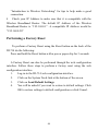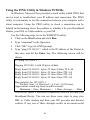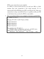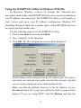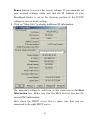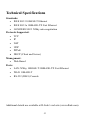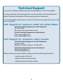
1
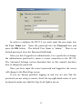
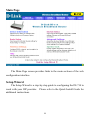
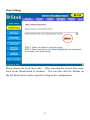
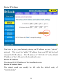
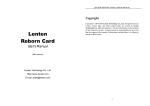
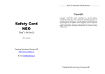
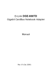
D-Link
DI-714
Wireless
Broadband Router
User’s Manual
Rev. 020205F
Contents
Introduction ................................................................................................5
Package Contents .....................................................................................6
Introduction to Broadband Router Technology........................................7
Introduction to Firewalls ..........................................................................7
Introduction to Local Area Networking ...................................................8
Introduction to Virtual Private Networking..............................................9
Introduction to Wireless Networking .....................................................10
Hardware Installation ..............................................................................12
Placement ...............................................................................................12
Safety Precautions ..................................................................................12
Front Panel .............................................................................................13
Dial-Up ...............................................................................................13
Wireless ..............................................................................................13
Local Ethernet ....................................................................................13
Rear Panel...............................................................................................13
DIAL-UP MODEM............................................................................13
Basic DI-714 Configuration & Main Page .............................................14
Start-up and Log in.................................................................................14
Main Page...............................................................................................16
Setup Wizard ..........................................................................................16
Time Settings......................................................................................17
Device IP Settings ..............................................................................18
Cable/DSL ISP Settings .....................................................................19
ISP Additional Settings ......................................................................20
Modem Settings..................................................................................22
Device Information.................................................................................23
2
Device Status..........................................................................................24
Basic Setup .............................................................................................25
Advanced Settings ....................................................................................27
DHCP Server Settings ............................................................................27
Virtual Server Settings............................................................................28
DMZ ...................................................................................................29
Static Routing .........................................................................................30
Dynamic Settings ...................................................................................31
Modem String Settings...........................................................................32
Password Settings...................................................................................33
System Tools..............................................................................................34
Intruder Detection Log ...........................................................................34
Display Routing Table............................................................................35
System Diagnostics ................................................................................37
Load Default Settings.............................................................................38
Upgrade Firmware..................................................................................39
Reset Device...........................................................................................40
Troubleshooting ........................................................................................41
Basic Functions ......................................................................................41
LAN Connection Problems ....................................................................43
ISP Connection Problems.......................................................................45
Internet Application Problems................................................................46
Wireless Troubleshooting.......................................................................47
Performing a Factory Reset....................................................................48
Using the PING Utility in Windows 95/98/Me......................................49
Using the WINIPCFG Utility in Windows 95/98/Me ............................51
Technical Specifications ...........................................................................53
Contacting Technical Support.................................................................54
Limited Warranty.....................................................................................55
3
Registration............................................................................................58
4
Introduction
Congratulations on your purchase of the D-Link Wireless Broadband
Router. Your Wireless Broadband Router enables you to share your DSL
or Cable Internet connection with computers on your network. This guide
will explain the features and functions of the Wireless Broadband Router to
help you get the most out of your Internet experience.
D-Link’s DI-714 allows LAN users to share a single Internet
Connection while providing the safety and security of port blocking,
packet filtering, and a natural firewall. Static address support, integrated
DHCP, PPPoE, and device name support will allow it to connect to nearly
any broadband provider whether Cable or DSL based, and at the same time
simplify local area network settings.
The DI-714 provides two levels of security support. First, it masks
local users’ IP addresses from others on the Internet making it much more
difficult for a hacker to target a machine on your network. Secondly, it
can block and redirect certain ports to limit the services that outside users
can access. Specific ports can be opened to ensure that games and other
Internet applications will run properly.
The Wireless Broadband Router provides special pass-through
support for common VPN implementations. The Virtual Server feature
allows you to expose HTTP, FTP, Game Servers and other local services to
be accessible to Internet users located outside of the LAN. The
User-Definable Application Sensing Tunnel feature allows you to define
the attributes to support special applications requiring multiple connections,
such as Internet gaming, video conferencing, and Internet telephony. A
DMZ setting can be applied to a single client behind the Wireless
5
Broadband Router to expose it to the Internet and ensure complete Internet
application compatibility even if specific ports are not known.
Unlike proxy server or NAT software that requires the software server
to remain visible on the Internet, local networked computers are not
directly externally visible when using the DI-714. Also the Wireless
Broadband Router, like broadband, is always on, removing the need to
constantly boot a software server when access is desired from a client.
Integrated DHCP services allow up to 253 users to get their IP address
automatically on boot up from the DI-714. Client machines require no
software (only the installed NIC card in a wireless network), simply set the
Ethernet or wireless adapters to accept a dynamically assigned IP address
and reboot. Each time they are powered up the DI-714 will recognize
them and set their IP address to instantly connect them to the LAN.
Package Contents
The D-Link DI-714 package should include the following items.
DI-714 Wireless Broadband router
User’s Manual
Quick Install Guide
Power Adapter
CAT-5 UTP Cable
6
Introduction to Broadband Router Technology
A router is a device that forwards data packets from a source to a
destination. Routers work on the OSI (Open System Interconnection)
Layer 3, which forwards data packets using IP addresses and not a MAC
(Media Access Control) address. A router will forward data from the
Internet to a particular computer on your LAN.
The information that makes up the Internet gets moved around using
routers. When you click on a link on a web page, you send a request to a
server to show you the next page. The information that is sent and
received from your computer is moved from your computer to the server
using routers. A router also determines the best route that your
information should follow to ensure that the information is delivered
properly.
A router controls the amount of data that is sent through your network
by eliminating information that should not be there. This provides
security for the computers behind your router because computers from the
outside cannot access or send information directly to any computer on your
network. The router determines which computer the information should
be forwarded to and sends it. If the information is not intended for any
computer on your network, the data is discarded. This keeps any
unwanted or harmful information from accessing or damaging your
network.
Introduction to Firewalls
A firewall is a device that sits between your computer and the Internet
that prevents unauthorized access to or from your network. A firewall
can be a computer using firewall software or a special piece of hardware
7
built specifically to act as a firewall. In most circumstances, a firewall is
used to prevent unauthorized Internet users from accessing private
networks such as corporate LAN’s and Intranets.
A firewall watches all of the information moving to and from your
network and analyzes each piece of data. Each piece of data is checked
against a set of criteria that the administrator configures. If any data does
not meet the criteria, that data is blocked and discarded. If the data meets
the criteria, the data is passed through. This method is called packet
filtering.
A firewall can also run specific security functions based on the type of
application or type of port that is being used. For example, a firewall can
be configured to work with an FTP or Telnet server. Or a firewall can be
configured to work with specific UDP or TCP ports to allow certain
applications or games to work properly over the Internet.
Introduction to Local Area Networking
Local Area Networking (LAN) is the term used when connecting
several computers together over a small area such as a building or group of
buildings. LAN’s can be connected over a large area. A collection of
LAN’s connected over a large area is called a Wide Area Network (WAN).
A LAN consists of multiple computers connected to each other.
There are many types of media that can connect computers together. The
most common media is CAT5 (Ethernet) cable; UTP or STP twisted pair
wire. On the other hand, wireless networks do not use wires; instead they
communicate over radio waves. Each computer must have a Network
Interface Card (NIC), which communicates the data between computers.
A NIC is usually a 10Mbps network card, or 10/100Mbps network card, or
8
a wireless network card.
Most networks use hardware devices such as hubs or switches that
each cable can be connected to in order to continue the connection between
computers. A hub simply takes any data arriving through each port and
forwards the data to all other ports. A switch is more sophisticated, in
that a switch can determine the destination port for a specific piece of data.
A switch minimizes network traffic overhead and speeds up the
communication over a network.
Networks take some time in order to plan and implement correctly.
There are many types of scenarios to consider which could affect the
operability of a network.
Introduction to Virtual Private Networking
Virtual Private Networking (VPN) uses a publicly wired network (the
Internet) to securely connect two different networks as if they were the
same network. For example, an employee can access the corporate
network from home using VPN, allowing the employee to access files and
printers. Here are several different implementations of VPN that can be
used.
Point-to-Point Tunneling Protocol (PPTP)
PPTP uses proprietary means of connecting two private networks over the
Internet. PPTP is a way of securing the information that is communicated
between networks. PPTP secures information by encrypting the data
inside of a data packet.
9
IP Security (IPSec)
IPSec provides a more secure network-to-network connection across the
Internet or a Wide Area Network (WAN).
IPSec encrypts all
communication between the client and server whereas PPTP only encrypts
the data packets.
Both of these VPN implementations are used because there is not a
standard for VPN server software. Because of this, each ISP or business
can implement its own VPN network making interoperability a challenge.
Introduction to Wireless Networking
D-Link wireless products are based on industry standards to provide
easy- to- use and compatible high-speed wireless connectivity within your
home or business. Strictly adhering to IEEE 802.11b the D-Link Air
wireless family of products will allow you to access the data you want,
when and where you want it. No longer will you be tethered to a
workstation or forced to run new wiring. You will be able to enjoy the
freedom that wireless networking delivers.
Standards Based Technology
Based on IEEE 802.11b, D-Link Air wireless products can throughput
data up to 11 Megabits per second.* This means you will be able to
transfer large files quickly or even watch a movie in MPEG format over
your network without noticeable delays. This technology works by using
multiple frequencies in the 2.4GHz range utilizing Direct Sequence Spread
Spectrum (DSSS) technology. D-Link Air products will automatically
sense the best possible connection speed to ensure the greatest speed and
range possible with the technology.
*Maximum wireless signal rate based on IEEE Standard 802.11b specifications. Actual data
throughput will vary. Network conditions and environmental factors, including volume of
network traffic, building materials and construction, and network overhead lower actual data
throughput rate.
10
Installation Considerations
Designed to go up to 300 feet indoors and up to 900 feet outdoors,
D-Link Air lets you access your network from virtually anywhere you
want. Keep in mind, however, that the number of walls, ceilings or other
objects that the wireless signals must pass thru will limit range. Typical
ranges vary depending on the types of materials and background RF noise
may be evident in your home or business. The key to maximizing range
is to follow these basic principles:
1. Keep the number of walls and ceilings to a minimum - Each wall or
ceiling can reduce your D-Link Air Wireless products range from 3-90
feet. Position your Access Points(base stations in a wireless network),
Routers, and Computers so that the number of walls or ceilings is
minimized.
2. Be aware of the direct line between Access Points, Wireless Broadband
Routers, and Computers - A wall that is 1 foot thick, at a 45 degree
angle appears to be almost 3 feet thick. At a 2 degree angle it looks
over 42 feet thick! Try to make sure that the AP and Adapters are
positioned so that the signal will travel straight through a wall or
ceiling for better reception.
3. Building Materials make a difference - A solid metal door or aluminum
studs may have a negative effect on range. Again, try to position
Access Points, Routers, and Computers so that the signal passes
through drywall or open doorways and not other materials.
4. Make sure that the antenna is positioned for best reception by using the
software signal strength tools included with your product.
5. Keep your product at least 3-6 feet away from electrical devices that
generate RF noise, like microwaves, Monitors, electric motors, etc.
11
For the average American multiple bedroom home, range should not be a
problem. If you experience low or no signal strength in areas of your
home that you wish to access, consider positioning the Access Point in a
location directly between the Routers and/or Computers that will be
connected. Additional Access Points can be connected to provide better
coverage in rooms where the signal does not appear as strong as desired.
Hardware Installation
Placement
The DI-714 Wireless Broadband Router should be placed in a safe and
secure location. To ensure proper operation, please keep the unit away
from water and other damaging elements.
Safety Precautions
Please read the installation guide thoroughly before you install the
DI-714.
The DI-714 should only be repaired by authorized and qualified
personnel.
Please do not try to open or repair the DI-714 yourself. Opening the
device will violate the products warranty.
Do not place the DI-714 in a damp or humid location, e.g. a bathroom.
The DI-714 should be placed in a sheltered and non-slip location
within a temperature range of 41 to 104 degrees Fahrenheit.
Please keep the plastic bag of the DI-714 and the clip binding the cable
out of reach of children and babies to avoid choking.
Please do not expose the DI-714 to direct sunlight or other heat
sources. The device’s housing and internal electronic components
may be damaged by direct sunlight or heat sources.
12
Front Panel
The front panel provides LED lights to indicate the status of the unit.
Refer to the following table for the meaning of each LED feature.
Power status of the DI-714. A steady LED indicates that
Power
the power is “on.” No LED light indicates lack of power.
Router status indicator. When the router starts up, the Status
Status
LED will briefly blink. If the unit is defective, then the
indicator will be constantly “on.”
Broadband Wide Area Network status. When connected to the
Cable/DSL modem, the LED indicator light is “on.”
Indicates Dial-Up modem status. When modem connection
Dial-Up
is established then the LED indicator light is “on.”
Indicates the status of the Wireless Access Point (AP.) When
Wireless
the Wireless AP is ready, the LED indicator is “on.”
Indicates link and activity of each Local Ethernet port.
Local
When a device (computer, hub or switch) is connected to
Ethernet
one of the Ethernet ports, the LED indicator is “on.” During
1234
(Link/Act) data transfer, the LED indicator light is “blinking.”
Rear Panel
The rear panel features the Local Ethernet ports, Broadband port, Dial-up
Modem port and Factory Reset button. Refer to the following table for the
meaning of each feature.
Used to connect to the power outlet. Only use the power
POWER
adapter provided with the DI-714. Use of an
unauthorized power adapter may cause damage to your
5V / DC
device and violate your warranty.
BROADBAND The RJ-45 Ethernet port labeled “Broadband” is used to
connect your DI-714 to your DSL or Cable modem.
Port used to connect an external backup modem.
DIAL-UP
MODEM
Resets the configuration to default factory settings.
RESET
13
Local Ethernet The Ethernet ports used to connect devices capable of
Ethernet connection such as a computer, hub, or switch.
1
2 3 4
The Ethernet
Ports will automatically detect a straight-through or
crossover cable.
Basic DI-714 Configuration & Main Page
The DI-714 provides a Web Configuration interface that can be
accessed using standard web browsers such as Netscape Communicator or
Microsoft Internet Explorer. Since the interface is web based (HTTP), the
DI-714 can be configured with any Java and HTML compliant Internet
browser in any operating system. This section will discuss the Web
Configuration interface and how to use different options and settings.
Although you can change the IP address of the DI-714 to meet your
needs, this manual will assume that the defaults are left in place. This
means that the IP address of your DI-714 will be 192.168.0.1. If you
have changed the IP address scheme, please substitute 192.168.0.1 with the
IP address scheme that you have chosen.
Start-up and Log in
In order to configure the DI-714, you must use your web browser and
manually input 192.168.0.1 into the Address box and press Enter. The
Main Page will appear. The Device Information and Device Status
screens can be seen without logging into the DI-714. However, when the
Setup Wizard, Basic Setup, Advanced Settings and System Tools buttons
are pressed, the log in screen will be shown.
14
In order to configure the DI-714 you must input the user-name into
the User Name box. Enter the password into the Password box and
press the OK button. The default User Name is “admin.” There is no
default password, leave the Password field blank.
Once you have logged-in as administrator, it is a good idea to change
the administrator password to ensure a secure connection to the DI-714.
The Advanced Settings section described later in this manual describes
how to change the password.
Once you have input the correct password and logged-in, the screen
will change to the Main Page screen.
If you are having problems logging in and you are sure that the
password you are using is correct, check the top right-hand corner of your
keyboard to make sure that the Caps Lock light is not on.
15
Main Page
The Main Page screen provides links to the main sections of the web
configuration interface.
Setup Wizard
The Setup Wizard is a step-by-step guide to configuring the DI-714 to
work with your ISP provider. Please refer to the Quick Install Guide for
additional instructions.
16
Time Settings
Please choose the local time zone.
After selecting the correct time zone,
click on the Next button to continue. You can also click the buttons on
the left hand side to reach a specific setting in the configuration.
17
Device IP Settings
You have to give your Internet gateway an IP address on your “private”
network. This is not the “public” IP address from your ISP but the local
internal LAN IP address. The IP address of “192.168.0.1” is the default
IP address of the LAN port in the broadband router.
Device IP Address
The internal LAN IP address of the broadband router.
Device IP Subnet Mask
The subnet mask can usually be left with the default entry of
“255.255.255.0”
18
Cable/DSL ISP Settings
The DSL/Cable ISP settings have a default to obtain dynamically the IP
address for the WAN port of the broadband router. Some ISPs may give
you Static IP settings. If this is the case for your ISP then you need to:
Enter the IP address that is assigned by your ISP
Enter the IP subnet mask
Enter the ISP gateway address
Enter the DNS IP address
19
ISP Additional Settings
If you would like to use ISP additional settings you have to enable this
function and configure this page. Some ISPs use this protocol for
authentication purposes; if this is the case, you need to enter:
User name: Enter the user name of your ISP account.
Password: Enter the password of your ISP account.
Retype password: Enter the password of your ISP account again to
re-confirm.
20
Some ISPs, especially cable modem providers, use the “Host Name” to
authenticate the user. If this is the case, you will need to enter:
Host Name: Enter the host name provided by the ISP.
Some ISPs require the user to input the MAC address of the original
Ethernet adapter. If this is the case, enter:
MAC Address: Enter the MAC address of the Ethernet adapter.
NOTE !
Some ISPs may recognize your LAN card MAC address as a legal user;
In this case, you have to copy the LAN card MAC address in the MAC address field.
For WIN 95/98 you can run winipcfg to see the LAN card MAC address
For WIN 2000/NT you can run ipconfig /all to see the LAN card MAC address
21
Modem Settings
An analog external modem can be used as a dialup backup to the
DSL/Cable connection. If you would like to use a modem backup, you
need to enable the modem settings function. Click on “Modem Settings”
on the left hand side and input the ISP account settings.
Note: If you change the baud rate settings, please check the initial string.
(Please refer to the modem’s manual.)
22
Device Information
The Device Information screen displays the basic information of your
DI-714. The Device Name is the same as the Computer Name that was set
in the Setup Wizard.
The IP Address is the IP Address assigned to LAN side of your
DI-714.
The Private LAN MAC Address the MAC Address assigned to the
LAN side of your DI-714.
The Public WAN (Cable/DSL) MAC Address is the MAC Address
assigned to the WAN port of the DI-714. This MAC Address may be
used by some cable modem connections. The Firmware Version is the
current firmware version used by the DI-714.
23
Device Status
The Device Status screen displays a graphical representation of your
current configuration. The left side of the screen shows your connection
information in regards to WAN and LAN IP Address information. The
right side displays the connection status of each device.
This means that there is a connection.
This means that there is not a connection.
24
The DHCP Log displays information about each IP Address assigned
to a computer using the DHCP server built-in to the DI-714.
Basic Setup
The Basic Setup screen enables you to change basic settings related to
accessing the Internet. All of the settings covered in the Basic Setup
section are covered in the Setup Wizard.
The Computer Name is used to give a name to your connection if
you are using a Cable modem.
The Domain Name (host name) is the name given to you by your ISP
provider if you are using the @Home cable Internet service.
Choose the Type of Connection you use by selecting Dynamic IP,
Static IP, or PPPoE.
25
Select Dynamic IP if your ISP has not given you a unique IP address
and you receive an automatic IP address each time you connect to your ISP.
The rest of the settings related to your connection are retrieved
automatically each time you connect to the Internet.
Select Static IP if your ISP assigns you an IP address. This means
that your ISP has given you an IP address that you will use to connect to
the Internet through their service. If you select Static IP, you will need to
enter the correct values for the IP Address, Subnet Mask and Gateway in
the fields provided.
Select PPPoE if your ISP uses the Point-to-Point over Ethernet
protocol to authenticate a username and password and then automatically
assign you an IP Address. PPP over Ethernet (PPPoE) is a non-standard
method of connecting to your ISP to obtain an IP address. It relies upon a
software client that is provided by the ISP. If you have a broadband
connection and login to your ISP like you would do with a dial-in modem,
then you are probably using PPPoE. If you are simply connected to the
Internet when you turn on your computer, you probably are not. The
safest way to check is to call your ISP or read the documentation provided
when you signed up for your Internet service. If you select PPPoE, you
will need to enter the correct values for your User Name and Password in
the fields provided. The DNS section needs to be set to the correct option
in order for the DI-714 to resolve domain name information in URL’s.
Select Dynamic DNS if your ISP provides the DNS information
much in the same way as you receive an IP Address.
Select Static DNS if you were given the DNS server information
when you signed with your ISP. Click on the Save & Restart button to
save your settings.
26
Advanced Settings
DHCP Server Settings
By default, the Broadband Router has DHCP server enabled to assign an IP
address ranging from 192.168.0.100 to 192.168.0.199. In addition, the
router is capable of reserving up to four IP addresses within the local
network for mail, web, or ftp server.
27
Virtual Server Settings
Specific application support is enabled in Virtual Server Settings
under Advanced Settings. Click on the arrow to select the common
applications such as FTP, Web server, and mail server. The DI-714
Broadband Router will detect and automatically open outgoing ports
required by most applications and games. However, some games and
applications such as MSNetmeeting will require that the computer be
exposed in the DMZ zone to allow incoming ports required by the
application. Click on the “Submit” button to save your settings.
28
DMZ
The Virtual Server Settings under Advanced Settings also enables one
computer to have full access to the Internet without the protection of the
firewall. This allows a computer to be exposed to unrestricted two-way
communication outside of your network.
To enable DMZ, click the checkbox to the left and select “All”. Then
type the IP address of the selected computer in the box provided. Click
the “Submit” button to save your changes.
Only one computer can use DMZ at a time. Please note that
enabling DMZ removes the protection of the firewall, which exposes
the computer to intrusion.
Use DMZ only when needed and not for extended periods of time.
In some circumstances with gaming, enabling DMZ may help the
game contact the maximum number of servers, which can improve ping
times. Once the game connects to the game server, disable DMZ to ensure
proper firewall protection.
29
Static Routing
In Static Routing, the user has the ability to add a static route to the
routing table by simple entering the destination IP, subnet mask, and
gateway. Clicking on “Add” and then “Submit” which requires a restart
for the IP address to be incorporated into the routing table.
30
Dynamic Settings
By default, the Broadband Router will not send or receive any routing
Internet protocols (RIP) to update the routing table. However, the user
can enable the Broadband Router to automatically send and receive RIP
packets to establish routes for commonly used paths.
31
Modem String Settings
Most dial-up modems are compatible with the standard modem
strings. However for modems that require special modem strings, the
user can enter the information in this screen.
32
Password Settings
You can give your Internet gateway a new password. This password will
be required the next time and subsequent times you configure your Internet
gateway. To enter a password, type your password in the new password
field and type it again in the retype password field.
Note: It is important to remember your password. If for any reason you
lose or forget your password, there is a small reset button located on the
back of the device. Pressing this button for 3 seconds will not only reset
the password, but also the device itself—and all previous configurations
will need to be input again.
33
System Tools
The System Tools section enables you to manage your DI-714 and
view information related to unit functions. The following functions are
described in this chapter.
Intruder Detection Log: View detection logs.
Display Routing Table: View routing table list.
System Diagnostics: Change remote configuration settings.
Load Default Settings: Restore settings to factory default.
Upgrade Firmware: Upgrade the firmware to a newer version.
Reset Device: Reboot the DI-714.
Intruder Detection Log
The Intruder Detection Log displays all information related to intrusion
34
attempts on your network. If any packets are seen as harmful, those
packets are blocked and a log is kept about the information related to that
packet.
Index: (1,2,3 etc.) Refers to the row number.
Time: The time that the action was logged.
Protocol: (IP, UDP etc.) The type of protocol detected.
Source IP (Port): The source IP address of the intruding packet.
Dest IP (Port): The IP address assigned to the destination of the
intruding packet.
Event: The type of intrusion.
Display Routing Table
The Display Routing Table screen displays the routing table that the
DI-714 is using. A router uses a routing table to keep track of what IP
35
addresses there are and where the router should forward packets when it
receives them.
Type: The type of routing protocol used.
Destination LAN IP Address: Shows the Destination IP Address on
the LAN side.
Subnet Mask: Shows the subnet mask assigned to the Destination
LAN IP Address.
Gateway IP Address: The IP Address of the assigned Gateway.
Hop Count: The number of hops between the Destination LAN IP
Address and the Gateway IP Address.
36
System Diagnostics
The System Diagnostics screen displays current status and connection
information. This screen is similar to the Device Status screen, although
both sections can be used to diagnose problems with your Internet
connection.
37
The Configuration section shows important information about your
ISP Settings, Modem Settings, and Device Settings as well as the current
firmware version the DI-714 is using.
The Diagnosis section shows important information about ISP Status,
Link Status, and the current WAN connection.
This information is very useful in troubleshooting connection
problems.
Load Default Settings
The Load Default Settings screen enables you to restore the settings
that came as default when set by D-Link. Click the Start button to begin
the process.
38
Upgrade Firmware
The Upgrade Firmware screen enables you to update the firmware
used in the DI-714. Visit D-Link’s product support site (www.dlink.com)
to download an updated firmware. Firmware updates usually fix
problems encountered by users, and may incorporate new features.
Begin by clicking the “Browse…” button to browse your computer to
select the updated firmware file. Once the firmware file is selected, click
the “Start” button to upgrade the firmware.
Note: When upgrading the firmware, do not try to access the
Internet and do not turn the power off. Doing so may cause the
firmware upgrade process to abort, which may result in corrupting the
firmware in your device.
39
Reset Device
The Reset Device screen enables you to reboot the DI-714. If any
changes are made and you want them to take effect, you will need to reset
the DI-714 to do so. Click the “Reboot” button to reset the DI-714.
Click the “Cancel” button to cancel.
When you press the “Reboot” button, the DI-714 will go through its
shutdown and boot-up process. The Internet will not be accessible until
the DI-714 has finished its reboot process.
40
Troubleshooting
In the event that you are unable to connect to or use your DI-714
Wireless Broadband Router, please refer to the following troubleshooting
guide. After each problem description, a possible cause and problem
resolution is provided. If this section does not help you fix the problem, go
to the D-Link web site (www.dlink.com) for additional troubleshooting tips.
If neither of these helps, please contact D-Link Technical Support for
additional help. The phone numbers for Technical Support are in the
appendix of this manual under D-Link Office Information.
Basic Functions
My Broadband Router will not turn on. No LED’s light up.
Cause:
The power is not connected or the power switch is set to “Off”.
Resolution:
Connect the power adapter to your Broadband Router and plug it into
the power outlet.
Make sure that the power switch is set to “On”.
Note: Only use the power adapter provided with your Broadband Router.
Using any other adapter may damage your Broadband Router and violate
your warranty.
41
LED’s don’t follow the correct boot-up sequence as stated in the Quick
Install Guide.
Cause:
The unit’s firmware is corrupt.
The unit is not receiving the correct voltage from the power supply.
Resolution:
Download and upgrade the latest firmware.
Make sure the correct firmware has been used while upgrading. Use
only the firmware provided on D-Link’s web or FTP sites.
Use only the power adapter provided.
The Link or Act LED’s do not turn on.
Cause:
The network cable is not connected.
The network cable is connected but not the right type, whether it is
patch or straight-through.
Resolution:
Make sure that both ends of the cable are connected.
Try using another cable.
If you are using a straight-through cable, try a patch cable and
vice-versa.
Sometimes my Broadband Router stops working or locks up.
Cause:
Someone has attempted to hack into someone on your LAN.
The Broadband Router has detected harmful data trying to access your
LAN.
42
The NAT table is full.
Resolution:
Reboot the Broadband Router by turning the power to the unit off and
then on again. Some types of hacker tools use very non-standard data
streams. Some of these streams may cause the Broadband Router to
lock up. When the Broadband Router locks up, it will not affect the
computers attached to it. You may need to restart the client computers
to regain Internet access.
Although sometimes inconvenient, a lock-up is an indication of an
attack. Part of the design of the Broadband Router is to act as a decoy
for such traffic. If your computer is locked up instead you may have
lost changes to open, unsaved files, lost data, or corrupted your
operating system or hard drive.
If you are currently experiencing frequent lock-ups, you may wish to
upgrade the firmware.
LAN Connection Problems
I can’t access my Broadband Router.
Cause:
The unit is not turned on.
There is not a network connection.
The computer you are using does not have a compatible IP Address.
Resolution:
Make sure your Broadband Router is turned on.
Make sure that there is a physical connection between your computer
and the Broadband Router and that the Link light is on.
43
Use the WINIPCFG utility described in the appendix to make sure that
your computer has a compatible IP Address. If your IP Address is not
set correctly and you are using DHCP, use WINIPCFG to renew your
IP Address. Otherwise, make correct changes to your Windows
network settings. Make sure that the IP Address used on your computer
is set to the same subnet as the Broadband Router. For example, if the
Broadband Router is set to 192.168.0.1, change the IP address of your
computer to 192.168.0.15 or another unique IP Address that
corresponds to the 192.168.0.X subnet.
Use the Reset button located on the front of your Broadband Router to
revert to the default settings.
I can’t connect to other computers on my LAN.
Cause:
The IP Addresses of the computers are not set correctly.
Network cables are not connected properly.
Windows network settings are not set correctly.
Resolution:
Make sure that each computer has a unique IP Address. If using DHCP
through the Broadband Router, make sure that each computer is set to
“Obtain an IP Address automatically” and restart the computer. Use the
WINIPCFG and PING utilities described in the appendix to make sure
that you can connect to each computer.
Make sure that the Link LED is on. If it is not, try a different network
cable.
Check each computer for correct network settings.
44
ISP Connection Problems
I can access the Broadband Router, but I can’t connect to my ISP.
Cause:
Your DSL or Cable modem is not functioning correctly.
The cable is connected from the WAN port of the Broadband Router to
your DSL or Cable modem.
The wrong connection type is used in Setup.
The username and password is not input correctly.
If using @Home service, the computer name is not input correctly.
Your ISP may only allow one MAC address to access the Internet.
You ISP may only allow one computer to access their service.
Resolution:
Make sure that your DSL or Cable modem is running correctly and
connected to the WAN port of the Broadband Router.
Make sure that the right connection type is used in the web
configuration.
Make sure that the username and password used in the connection type
is correct.
If using @Home, make sure that the computer name is input correctly.
Clone the MAC address using the web configuration interface.
Some ISP's do not care if you share your broadband connection among
multiple users. Other ISP's will explicitly restrict this type of activity in
your service contract. It is important that you verify that you are in
accordance with your service agreement before sharing Internet access.
45
Internet Application Problems
My online game does not work.
Cause:
The NAT table has filled up.
The correct settings have not been used to open the correct ports for
your application.
The unit has stopped working or crashed.
Resolution:
If you are trying to connect to game servers and your connection has
stopped working, wait a few minutes or turn the unit off and then on
again. Games send out many requests to many different servers trying
to find the best game server for your connection. When this is done, the
NAT table used in the Broadband Router can fill up and stop working
temporarily. Try using the DMZ host feature while connecting to game
servers and then disabling DMZ while playing the game.
Turn the Broadband Router off and then on again to reset the NAT
table.
Make sure that the correct ports have been opened in order for your
specific game to operate correctly behind a firewall. Consult your game
documentation or contact the technical support of the game company to
obtain the correct settings for your game.
Some games just won’t operate correctly behind a firewall. In this case,
use the DMZ host feature while using the game, then turning DMZ off
while the game is not being played to ensure proper firewall protection.
46
My E-Mail program doesn’t receive my E-Mail
Cause:
The Domain Suffix is not set correctly.
Resolution:
Some email applications require you to enter the Domain Suffix when
you configure your network and TCP/IP settings. The Domain Suffix is
the unique identifier for your email server.
The Domain Suffix is the Internet Protocol (TCP/IP) address of the
email server you are using. Your cable modem or DSL provider usually
lists it somewhere on your invoice. The Domain Suffix address should
appear similar to this: dlink.occa.home.com. Find the Domain Suffix
on your invoice or call your Internet Service Provider (ISP) to obtain it.
Wireless Troubleshooting
Can’t access the Broadband Router from a wireless network card
Cause:
Settings are not the same among each wireless adapter.
Out of range.
IP Address is not set correctly.
Resolution:
Make sure that the Mode, SSID, Channel and encryption settings are
set the same on each wireless adapter. The default SSID and Channel
that the Wireless Broadband Router uses is “default” and “6”
respectively.
Make sure that your computer is within range and free from any strong
electrical devices that may cause interference. Refer to the section
47
“Introduction to Wireless Networking” for tips to help make a good
connection.
Check your IP Address to make sure that it is compatible with the
Wireless Broadband Router. The default IP Address of the Wireless
Broadband Router is “192.168.0.1”. A compatible IP Address would be
“192.168.0.50”
Performing a Factory Reset
To perform a Factory Reset using the Reset button on the back of the
DI-714 do the following:
Press and hold the Reset button with a pen or paper clip for 3 seconds.
A Factory Reset can also be performed through the web configuration
interface. Follow these steps to perform a factory reset using the web
configuration interface.
1.
Log-in to the DI-714 web configuration interface.
2.
Click on the System Tools link at the bottom of the screen.
3.
4.
Click on Load Default Settings.
You will be asked if you want to restore to default settings. Click
OK to restore settings to default configuration or click Cancel.
48
Using the PING Utility in Windows 95/98/Me
In Windows, Microsoft has provided a small utility called PING that
can be used to troubleshoot your IP address and connection. The PING
utility is used mainly to test the connection between your computer and a
client computer. Using the PING utility to check a connection can be
helpful in determining where the problem is, whether it be your Broadband
Router, your DSL or Cable modem, or your ISP.
Use the following steps to use the WINIPCFG utility:
Click on the Start button and click Run.
Type "command" in the Open box.
Click "OK" to get to a DOS prompt.
Type "ping 192.168.0.1", which is the IP address of the Router in
this case, and hit the Enter key. The following screen will be
shown.
C:\>ping 192.168.0.1
Pinging 192.168.0.1 with 32 bytes of data:
Reply from 192.168.0.1: bytes=32 time=130ms TTL=64
Reply from 192.168.0.1: bytes=32 time=10ms TTL=64
Reply from 192.168.0.1: bytes=32 time=20ms TTL=64
Reply from 192.168.0.1: bytes=32 time=10ms TTL=64
Ping statistics for 192.168.0.1:
Packets: Sent = 4, Received = 4, Lost = 0 (0% loss),
Approximate round trip times in milli-seconds:
Minimum = 10ms, Maximum = 130ms, Average = 42ms
This screen shows a successful connection between you and your
Broadband Router. You can use these same steps to ping your
DSL or Cable modem and then your ISP provider and Internet
website. If any one of these attempts results in an unsuccessful
49
PING, your connection is not complete.
If a PING is unsuccessful between you and your DSL or Cable
modem, then your connection is not setup correctly. If it is
unsuccessful when PINGing your ISP or an Internet site, then your
connection is setup correctly but there is a problem with your ISP
or the Internet site you tried to PING is unavailable.
The screen shown below is an example of an unsuccessful PING.
C:\>ping 192.168.0.1
Pinging 192.168.0.1 with 32 bytes of data:
Request timed out.
Request timed out.
Request timed out.
Request timed out.
Ping statistics for 192.168.0.1:
Packets: Sent = 4, Received = 0, Lost = 4 (100% loss),
Approximate round trip times in milli-seconds:
Minimum = 0ms, Maximum = 0ms, Average = 0ms
50
Using the WINIPCFG Utility in Windows 95/98/Me
In Microsoft Windows versions 95 through Me, Microsoft has
provided a small utility called WINIPCFG that can be used to troubleshoot
your IP address and connection. The WINIPCFG utility is used mainly to
view, release and renew your IP Address configuration. Windows NT
(including Windows 2000) has a similar utility called IPCONFIG that can
be used to perform similar tasks.
Use the following steps to use the WINIPCFG utility:
Click on the Start button and click Run
Type "winipcfg" in the Open box.
Click OK. The IP Configuration screen will be displayed.
D-Link DFE-530TX PCI Fast Eth
The IP address will be displayed in the IP Address box. If you have
more than one network card, make sure that the network card that
you are using is displayed in the white dropdown box.
Make sure that the Default Gateway is the IP Address of your
Broadband router. If it is not, you will not be able to connect to the
Internet. If you are using DHCP, click the Release and then the
51
Renew buttons to receive the correct settings. If you manually set
your network settings, make sure that the IP Address of your
Broadband Router is set in the Gateway portion of the TCP/IP
settings in your network settings.
Click on "More Info" to display additional IP information.
D-Link DFE-530TX PCI Fast E
The important settings to watch for in this screen are in the Host
Information box. Make sure that the DNS Servers box has the
correct DNS information.
Also check the DHCP server box to make sure that you are
connected to the right DHCP server.
52
Technical Specifications
Standards:
• IEEE 802.3 10BASE-T Ethernet
• IEEE 802.3u 100BASE-TX Fast Ethernet
• ANSI/IEEE 802.3 NWay auto-negotiation
Protocols Supported:
• TCP
• IP
• NAT
• UDP
• PPPoE
• DHCP (Client and Server)
Management:
• Web-Based
Ports:
•
•
•
LAN: NWay 10BASE-T/100BASE-TX Fast Ethernet
WAN: 10BASE-T
RS-232 (DB-9) Console
Additional details are available at D-Link’s web site (www.dlink.com).
53
Technical Support
You can find software updates and user documentation on the D-Link website.
D-Link provides free technical support for customers within the United States and
within Canada for the duration of the warranty period on this product.
U.S. and Canadian customers can contact D-Link technical support through our web
site, or by phone.
Tech Support for customers within the United States:
D-Link Technical Support over the Telephone:
(877) 453-5465
24 hours a day, seven days a week.
D-Link Technical Support over the Internet:
http://support.dlink.com
email:[email protected]
Tech Support for customers within Canada:
D-Link Technical Support over the Telephone:
(800) 361-5265
Monday to Friday 7:30am to 12:00am EST
D-Link Technical Support over the Internet:
http://support.dlink.ca
email:[email protected]
When contacting technical support, please provide the following information:
• Serial number of the unit
• Model number or product name
• Software type and version number
54
Subject to the terms and conditions set forth herein, D-Link Systems, Inc. (“D-Link”) provides this
Limited Warranty:
•
•
Only to the person or entity that originally purchased the product from D-Link or its authorized
reseller or distributor, and
Only for products purchased and delivered within the fifty states of the United States, the District of
Columbia, U.S. Possessions or Protectorates, U.S. Military Installations, or addresses with an APO
or FPO.
Limited Warranty: D-Link warrants that the hardware portion of the D-Link product described below
(“Hardware”) will be free from material defects in workmanship and materials under normal use from the
date of original retail purchase of the product, for the period set forth below (“Warranty Period”), except
as otherwise stated herein.
•
•
•
Hardware (excluding power supplies and fans): One (1) year
Power supplies and fans: One (1) year
Spare parts and spare kits: Ninety (90) days
The customer's sole and exclusive remedy and the entire liability of D-Link and its suppliers under this
Limited Warranty will be, at D-Link’s option, to repair or replace the defective Hardware during the
Warranty Period at no charge to the original owner or to refund the actual purchase price paid. Any
repair or replacement will be rendered by D-Link at an Authorized D-Link Service Office. The
replacement hardware need not be new or have an identical make, model or part. D-Link may, at its
option, replace the defective Hardware or any part thereof with any reconditioned product that D-Link
reasonably determines is substantially equivalent (or superior) in all material respects to the defective
Hardware. Repaired or replacement hardware will be warranted for the remainder of the original
Warranty Period or ninety (90) days, whichever is longer, and is subject to the same limitations and
exclusions. If a material defect is incapable of correction, or if D-Link determines that it is not practical
to repair or replace the defective Hardware, the actual price paid by the original purchaser for the
defective Hardware will be refunded by D-Link upon return to D-Link of the defective Hardware. All
Hardware or part thereof that is replaced by D-Link, or for which the purchase price is refunded, shall
become the property of D-Link upon replacement or refund.
Limited Software Warranty: D-Link warrants that the software portion of the product (“Software”) will
substantially conform to D-Link’s then current functional specifications for the Software, as set forth in
the applicable documentation, from the date of original retail purchase of the Software for a period of
ninety (90) days (“Software Warranty Period”), provided that the Software is properly installed on
approved hardware and operated as contemplated in its documentation. D-Link further warrants that,
during the Software Warranty Period, the magnetic media on which D-Link delivers the Software will be
free of physical defects. The customer's sole and exclusive remedy and the entire liability of D-Link and
its suppliers under this Limited Warranty will be, at D-Link’s option, to replace the non-conforming
Software (or defective media) with software that substantially conforms to D-Link’s functional
specifications for the Software or to refund the portion of the actual purchase price paid that is
attributable to the Software. Except as otherwise agreed by D-Link in writing, the replacement Software
is provided only to the original licensee, and is subject to the terms and conditions of the license granted
by D-Link for the Software. Replacement Software will be warranted for the remainder of the original
Warranty Period and is subject to the same limitations and exclusions. If a material non-conformance is
incapable of correction, or if D-Link determines in its sole discretion that it is not practical to replace the
non-conforming Software, the price paid by the original licensee for the non-conforming Software will be
refunded by D-Link; provided that the non-conforming Software (and all copies thereof) is first returned
to D-Link. The license granted respecting any Software for which a refund is given automatically
terminates.
Non-Applicability of Warranty: The Limited Warranty provided hereunder for Hardware and Software
portions of D-Link's products will not be applied to and does not cover any refurbished product and any
product purchased through the inventory clearance or liquidation sale or other sales in which D-Link, the
sellers, or the liquidators expressly disclaim their warranty obligation pertaining to the product and in that
case, the product is being sold "As-Is" without any warranty whatsoever including, without limitation, the
Limited Warranty as described herein, notwithstanding anything stated herein to the contrary.
Submitting A Claim: The customer shall return the product to the original purchase point based on its
return policy. In case the return policy period has expired and the product is within warranty, the
customer shall submit a claim to D-Link as outlined below:
•
The customer must submit with the product as part of the claim a written description of the
Hardware defect or Software nonconformance in sufficient detail to allow D-Link to confirm the
same, along with proof of purchase of the product (such as a copy of the dated purchase invoice
for the product) if the product is not registered.
•
The customer must obtain a Case ID Number from D-Link Technical Support at 1-877-453-5465,
who will attempt to assist the customer in resolving any suspected defects with the product. If the
product is considered defective, the customer must obtain a Return Material Authorization (“RMA”)
number by completing the RMA form and entering the assigned Case ID Number at
https://rma.dlink.com/.
•
After an RMA number is issued, the defective product must be packaged securely in the original or
other suitable shipping package to ensure that it will not be damaged in transit, and the RMA
number must be prominently marked on the outside of the package. Do not include any manuals
or accessories in the shipping package. D-Link will only replace the defective portion of the product
and will not ship back any accessories.
•
The customer is responsible for all in-bound shipping charges to D-Link. No Cash on Delivery
(“COD”) is allowed. Products sent COD will either be rejected by D-Link or become the property of
D-Link. Products shall be fully insured by the customer and shipped to D-Link Systems, Inc.,
17595 Mt. Herrmann, Fountain Valley, CA 92708. D-Link will not be held responsible for any
packages that are lost in transit to D-Link. The repaired or replaced packages will be shipped to
the customer via UPS Ground or any common carrier selected by D-Link. Return shipping charges
shall be prepaid by D-Link if you use an address in the United States, otherwise we will ship the
product to you freight collect. Expedited shipping is available upon request and provided shipping
charges are prepaid by the customer.
D-Link may reject or return any product that is not packaged and shipped in strict compliance with the
foregoing requirements, or for which an RMA number is not visible from the outside of the package. The
product owner agrees to pay D-Link’s reasonable handling and return shipping charges for any product
that is not packaged and shipped in accordance with the foregoing requirements, or that is determined
by D-Link not to be defective or non-conforming.
What Is Not Covered: The Limited Warranty provided herein by D-Link does not cover: Products that,
in D-Link’s judgment, have been subjected to abuse, accident, alteration, modification, tampering,
negligence, misuse, faulty installation, lack of reasonable care, repair or service in any way that is not
contemplated in the documentation for the product, or if the model or serial number has been altered,
tampered with, defaced or removed; Initial installation, installation and removal of the product for repair,
and shipping costs; Operational adjustments covered in the operating manual for the product, and
normal maintenance; Damage that occurs in shipment, due to act of God, failures due to power surge,
and cosmetic damage; Any hardware, software, firmware or other products or services provided by
anyone other than D-Link; and Products that have been purchased from inventory clearance or
liquidation sales or other sales in which D-Link, the sellers, or the liquidators expressly disclaim their
warranty obligation pertaining to the product. While necessary maintenance or repairs on your Product
can be performed by any company, we recommend that you use only an Authorized D-Link Service
Office. Improper or incorrectly performed maintenance or repair voids this Limited Warranty.
Disclaimer of Other Warranties: EXCEPT FOR THE LIMITED WARRANTY SPECIFIED HEREIN,
THE PRODUCT IS PROVIDED “AS-IS” WITHOUT ANY WARRANTY OF ANY KIND WHATSOEVER
INCLUDING, WITHOUT LIMITATION, ANY WARRANTY OF MERCHANTABILITY, FITNESS FOR A
PARTICULAR PURPOSE AND NON-INFRINGEMENT. IF ANY IMPLIED WARRANTY CANNOT BE
DISCLAIMED IN ANY TERRITORY WHERE A PRODUCT IS SOLD, THE DURATION OF SUCH
IMPLIED WARRANTY SHALL BE LIMITED TO THE DURATION OF THE APPLICABLE WARRANTY
PERIOD SET FORTH ABOVE. EXCEPT AS EXPRESSLY COVERED UNDER THE LIMITED
WARRANTY PROVIDED HEREIN, THE ENTIRE RISK AS TO THE QUALITY, SELECTION AND
PERFORMANCE OF THE PRODUCT IS WITH THE PURCHASER OF THE PRODUCT.
Limitation of Liability: TO THE MAXIMUM EXTENT PERMITTED BY LAW, D-LINK IS NOT LIABLE
UNDER ANY CONTRACT, NEGLIGENCE, STRICT LIABILITY OR OTHER LEGAL OR EQUITABLE
THEORY FOR ANY LOSS OF USE OF THE PRODUCT, INCONVENIENCE OR DAMAGES OF ANY
CHARACTER, WHETHER DIRECT, SPECIAL, INCIDENTAL OR CONSEQUENTIAL (INCLUDING,
BUT NOT LIMITED TO, DAMAGES FOR LOSS OF GOODWILL, LOSS OF REVENUE OR PROFIT,
WORK STOPPAGE, COMPUTER FAILURE OR MALFUNCTION, FAILURE OF OTHER EQUIPMENT
OR COMPUTER PROGRAMS TO WHICH D-LINK’S PRODUCT IS CONNECTED WITH, LOSS OF
INFORMATION OR DATA CONTAINED IN, STORED ON, OR INTEGRATED WITH ANY PRODUCT
RETURNED TO D-LINK FOR WARRANTY SERVICE) RESULTING FROM THE USE OF THE
PRODUCT, RELATING TO WARRANTY SERVICE, OR ARISING OUT OF ANY BREACH OF THIS
LIMITED WARRANTY, EVEN IF D-LINK HAS BEEN ADVISED OF THE POSSIBILITY OF SUCH
DAMAGES. THE SOLE REMEDY FOR A BREACH OF THE FOREGOING LIMITED WARRANTY IS
REPAIR, REPLACEMENT OR REFUND OF THE DEFECTIVE OR NON-CONFORMING PRODUCT.
THE MAXIMUM LIABILITY OF D-LINK UNDER THIS WARRANTY IS LIMITED TO THE PURCHASE
PRICE OF THE PRODUCT COVERED BY THE WARRANTY. THE FOREGOING EXPRESS WRITTEN
WARRANTIES AND REMEDIES ARE EXCLUSIVE AND ARE IN LIEU OF ANY OTHER WARRANTIES
OR REMEDIES, EXPRESS, IMPLIED OR STATUTORY.
Governing Law: This Limited Warranty shall be governed by the laws of the State of California. Some
states do not allow exclusion or limitation of incidental or consequential damages, or limitations on how
long an implied warranty lasts, so the foregoing limitations and exclusions may not apply. This Limited
Warranty provides specific legal rights and you may also have other rights which vary from state to
state.
Trademarks: D-Link is a registered trademark of D-Link Systems, Inc. Other trademarks or registered
trademarks are the property of their respective owners.
Copyright Statement: No part of this publication or documentation accompanying this product may be
reproduced in any form or by any means or used to make any derivative such as translation,
transformation, or adaptation without permission from D-Link Corporation/D-Link Systems, Inc., as
stipulated by the United States Copyright Act of 1976 and any amendments thereto. Contents are
subject to change without prior notice. Copyright 2005 by D-Link Corporation/D-Link Systems, Inc. All
rights reserved.
CE Mark Warning: This is a Class B product. In a domestic environment, this product may cause radio
interference, in which case the user may be required to take adequate measures.
FCC Statement: This equipment has been tested and found to comply with the limits for a Class B
digital device, pursuant to part 15 of the FCC Rules. These limits are designed to provide reasonable
protection against harmful interference in a residential installation. This equipment generates, uses, and
can radiate radio frequency energy and, if not installed and used in accordance with the instructions,
may cause harmful interference to radio communication. However, there is no guarantee that
interference will not occur in a particular installation. If this equipment does cause harmful interference
to radio or television reception, which can be determined by turning the equipment off and on, the user
is encouraged to try to correct the interference by one or more of the following measures:
•
•
•
•
Reorient or relocate the receiving antenna.
Increase the separation between the equipment and receiver.
Connect the equipment into an outlet on a circuit different from that to which the receiver is
connected.
Consult the dealer or an experienced radio/TV technician for help.
For detailed warranty information applicable to products purchased outside the United
States, please contact the corresponding local D-Link office.
Product registration is entirely voluntary and failure to complete or return this
form will not diminish your warranty rights.
58