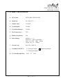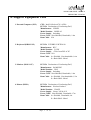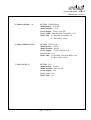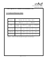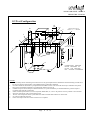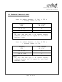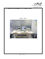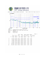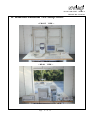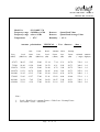
1
NVLAP LAB CODE:200097-0
REPORT NO. :E910739
FCC DoC TEST REPORT
According to
FCC Part 15 Subpart B
Test
: SWITCHING HUB 8-PORT
Item
Model
: ES-3108P V7.0, GS-D08P
No.
: EDIMAX TECHNOLOGY CO., LTD.
Responsible
Party
7, LANE 116, WU-KUNG SECOND ROAD, WU-KU
Address
INDUSTRIAL PARK, TAIWAN, R. O. C.
Test Engineer :
FISH YU
Test Date
:
NOV.
29,
2002
Issued Date
:
JAN.
27,
2003
NVLAP Signature :
Peter Kao
Peter Kao / Director
•The test report shall not be reproduced except in full, without the written approval of
the laboratory.
•The report must not be used by the client to claim product endorsement by NVLAP or any
agency of the United States government.
•This report is only for item test which described in page 5.
•The testing result in this report are traceable to national and international standard .
PEP TESTING LABORATORY
12-3Fl, No. 27-1, Lane 169, Kang-Ning St., Hsi-Chih,
Taipei Hsien, Taiwan, R. O. C.
TEL : 8862-26922097 FAX : 8862-26956236
Page 1
of 27
NVLAP LAB CODE:200097-0
REPORT NO. :E910739
Table of Contents
1.
SCOPE
3
2.
PRODUCT INFORMATION
4
3.
EUT DESCRIPTION AND TEST METHODS
5
4.
MODIFICATION(S)
6
5.
TEST SOFTWARE USED
6
6.
SUPPORT EQUIPMENT USED
7
7.
DESCRIPTION OF CONDUCTED EMISSIONS TEST
9
8.
DESCRIPTION OF RADIATED EMISSIONS TEST
10
9.
CONDUCTED EMISSIONS TEST SETUP PHOTO.
13
10.
CONDUCTED EMISSIONS TEST DATA
14
11.
RADIATED EMISSIONS TEST SETUP PHOTO.
17
12.
RADIATED EMISSIONS TEST DATA
18
13.
LIST OF MEASURED INSTRUMENTS
20
14.
DUTIES OF THE RESPONSIBLE PARTY
21
15.
LABELLING REQUIREMENTS
22
16.
INFORMATION TO THE USER
23
17.
EUT PHOTOGRAPHS
24
Page 2
of 27
NVLAP LAB CODE:200097-0
REPORT NO. :E910739
1. Scope
Measurement and determination of electromagnetic emissions (EME) of radio frequency devices
including intentional and/or unintentional radiators for compliance with the technical rules and
regulations of the Federal Communications Commission under ET Docket 95-19 Declaration of
Conformity(DoC).
Responsible Party*:
EDIMAX TECHNOLOGY CO., LTD.
Address:
7, LANE 116, WU-KUNG SECOND ROAD, WU-KU
INDUSTRIAL PARK, TAIPEI HSIEN, TAIWAN, R. O. C.
Contact Person:
TRACY CHENG / ASSISTANT
Phone No.:
886-2-22995648
Fax No.:
² Regulation:
FCC Part 15 & Part 2; Docket 95-19
² Limitation:
CISPR 22 CLASS B
² Test Procedure:
ANSI C63.4(1992)
² Test Item:
SWITCHING HUB 8-PORT
² Model No.:
ES-3108P V7.0, GS-D08P
² Serial No.:
N/A
² Place of Test:
PEP Testing Laboratory
886-2-22995647
12-3Fl, No. 27-1, Lane 169, Kang-Ning St., Hsi-Chih,
Taipei Hsien, Taiwan, R. O. C.
TEL : 8862-26922097 FAX : 8862-26956236
Page 3
of 27
NVLAP LAB CODE:200097-0
REPORT NO. :E910739
2. Product Information
a.
EUT Name:
SWITCHING HUB 8-PORT
b. Model No.:
ES-3108P V7.0
c.
VT6508X
Chipset Type:
d. System Speed:
25 MHz
e.
Crystal/Oscillator(s) : 25 MHz
f.
Port/Connector(s) :
UTP
g. Memory Expansion:
N/A
h. Power Rating:
Adapter ---------Model No. : AD41-1200500DU
Input : AC 120V 60Hz 200mA
Output : DC 12V 500mA
i.
Chassis Used:
PLASTIC (ABS V0)
j.
Condition of the EUT :
k. Test Item Receipt Date :
□ Prototype Sample 3 Engineering Sample
□ Production Sample
NOV.
27,
Page 4
2002
of 27
NVLAP LAB CODE:200097-0
REPORT NO. :E910739
3. EUT Description and test methods
The equipment under test (EUT) is SWITCHING HUB 8-PORT model ES-3108P
V7.0/GS-D08P. The EUT that contains eight RJ-45 ports is used for networking. It supports
10/100Mbps auto-negotiation on all RJ-45 ports. AC-DC switching power adaptor supplies
EUT DC 12V from AC main power. For more detail specification about the EUT, please
refer to the user’s manual.
Test method: The EUT configuration was setup by the following steps for test.
(A) Connect EUT one RJ-45 port to host PC LAN card on turntable.
(B) Connect EUT another RJ-45 port to remote PC LAN card off turntable.
(C) Terminate all the rest of EUT RJ-45 ports by free-ended data cables.
All corresponding peripherals to host PC I/O ports and EUT on turntable were
setup to proceed with the test. After respectively pre-testing EUT at
10-10Mbps and 100-100Mbps, we took the worst-case test mode:
100-100Mbps for final test, and the worst-case test result was recorded and
provided in this report.
As pre-scan, we took radiated emission first. EUT configuration including peripheral devices
placement and data cables coupling was compliant with ANSI C63.4 requirement. Test
engineer tried to find the worst data cables coupling in order to perform the final test that
conducted emission and radiated emission would keep the same configuration under test.
Conducted emission test:
The system was setup with the EMI diagnostic software running. The power line conducted
EMI tests were run on the line and neutral conductors of the power cord and the results were
recorded. The effect of varying the position of the interface cables has been investigated to
find the worst-case configuration that produces maximum emission.
At the frequencies where the peak values of the emission exceeded the quasi-peak limit, the
emissions were also measured with the quasi-peak detectors. The average detector also
measured the emission either (A) quasi-peak values were under quasi-peak limit but exceeded
average limit, or (B) peak values were under quasi-peak limit but exceeded average limit.
Radiated emission test:
The maximum readings were found by varying the height of antenna and then rotating the
turntable. Both polarization of antenna, horizontal and vertical, are measured. The effect of
varying the position of the interface cables has been investigated to find the configuration that
produces maximum emission.
The highest emissions were also analyzed in details by operating the spectrum analyzer in
fixed tuned quasi-peak mode to determine the precise amplitude of the emissions. While
doing so, the antenna height was varied between one and four meters, and the turntable was
slowly rotated, to maximize the emission.
Page 5
of 27
NVLAP LAB CODE:200097-0
REPORT NO. :E910739
4. Modification(s):
N/A
5. Test Software Used
(A) PING.EXE was the command used to deliver signals between two PCs via EUT during
the test.
Page 6
of 27
NVLAP LAB CODE:200097-0
REPORT NO. :E910739
6. Support Equipment Used
1.Personal Computer (PC3)
CPU : Intel P4 Socket 478 1.6GHz
FCC ID:Declaration of Conformity(DoC)
Manufacturer:LEMEL
Model Number:LMIH1A2
Power Supply:Switching
Power Cord:Non-Shielded, Detachable, 1.8m
Data Cable:N/A
2.Keyboard (KBS1 PS/2)
FCC ID:E5XKB5121WTH0110
Manufacturer:BTC
Model Number:5121W
Power Supply:+5Vdc from PS2 of PC
Power Cord:N/A
Data Cable:1 > Shielded , Non-detachable,1.6m
2 > Back Shell : Metal
3.Monitor (MON1 15”)
FCC ID:Declaration of Conformity(DoC)
Manufacturer:SAMSUNG
Model Number:550S
Power Supply:Switching
Power Cord:Non-Shielded, Detachable, 1.8m
Data Cable:1 > Shielded , Non-detachable,1.5m
2 > Back Shell : Metal
4.Printer (PRN1)
FCC ID:Declaration of Conformity(DoC)
Manufacturer:Hewlett-Packard
Model Number:C2642E
Power Supply:Linear, 30Vdc O/P
Power Cable:Non-Shielded , Detachable,1.7m
Data Cable:1 > Shielded , Detachable,1m
2 > Back Shell : Metal
Page 7
of 27
NVLAP LAB CODE:200097-0
REPORT NO. :E910739
5.Modem (MOD1) ×2
FCC ID:IFAXDM1414
Manufacturer:ACEEX
Model Number:1414
Power Supply:Linear, 9Vac O/P
Power Cable:Non-Shielded , Detachable,1.7m
Data Cable:1 > Shielded , Detachable,1m
2 > Back Shell : Metal
6.Mouse (MOUS/1 PS/2)
FCC ID:DZL211106
Manufacturer:ACER
Model Number:M-S42
Power Supply:+5Vdc from PS2 of PC
Power Cord:N/A
Data Cable:1 > Shielded , Non-detachable,1.8m
2 > Back Shell : Metal
7.Lan Card (LC1)
FCC ID:N/A
Manufacturer:D-Link
Model Number:DFE-530TX
Power Supply:N/A
Power Cord:N/A
Data Cable:N/A
Page 8
of 27
NVLAP LAB CODE:200097-0
REPORT NO. :E910739
7. Description of Conducted Emissions Test
7.1 Conducted Emissions Limits
Frequency
Maximum RF Line Voltage dB(uV)
Class A
Class B
MHz
QUASIPEAK
AVERAGE
QUASIPEAK
AVERAGE
0.15 - 0.50
79
66
66-56
56-46
0.50 - 5.0
73
60
56
46
5.0 - 30
73
60
60
50
Remarks : In the above table, the tighter limit applies at the band edges.
Page 9
of 27
NVLAP LAB CODE:200097-0
REPORT NO. :E910739
8. Description of Radiated Emissions Test
8.1 Radiated Emissions
Preliminary measurements were made indoors chamber at 3 meter using broadband antennas,
broadband amplifier, and spectrum analyzer to determine the frequency producing the
maximum EME. Appropriate precaution was taken to ensure that all EME from the EUT
were maximized and investigated. The system configuration, clock speed, mode of operation
or video resolution, turntable azimuth with respect to the antenna were noted for each
frequency found. The spectrum was scanned from 30 to 1000 MHz using logbicon antenna.
Above 1GHz, linearly polarized double ridge horn antenna was used.
Final measurements were made outdoors at 10-meter test range using logbicon antenna and
horn antenna. The test equipment was placed on a wooden bench situated on a 1.5x1 meter
area adjacent to the measurement area. Sufficient time for the EUT, support equipment, and
test equipment was allowed in order for them to warm up to their normal operating
condition. Each frequency found during pre-scan measurements was re-examined and
investigated using Quasi-Peak Adapter. The detector function was set to CISPR quasi-peak
mode and the bandwidth of the receiver was set to 120kHz.
The turntable containing the system was rotated; the antenna height was varied 1 to 4
meters and stopped at the azimuth or height producing the maximum emission. Each
emission was maximized by: varying mode of operation or resolution; clock or data
exchange speed; scrolling H pattern to the EUT and/or support equipment, and powering
the monitor from the floor mounted outlet box and the computer aux AC outlet , if
applicable; and changing the polarity of the antenna, whichever determined the worst-case
emission. Photographs of the worst-case emission can be seen in radiated emission test
photo.
Page 10
of 27
NVLAP LAB CODE:200097-0
REPORT NO. :E910739
8.2 Test Configuration
10
cm
10
cm
EUT
NONCONDUCTIVE
TABLE 1.5 x 1 METER
5
5
6
80 cm TO
GROUND PLANE
7
4
2
1
8
3
40 cm
8
CONDUCTING GROUND
PLANE EXTENDS AT
LEAST 0.5m BEYOND
EUT SYSTEM FOOTPRINT
LEGEND
1.
Interconnecting cables which hang closer than 40 cm to the ground plane shall be folded back and forth forming a bundle 30 to
40 cm long. hanging approximately in the middle between ground plane and table.
2.
I/O cables which are connected to a peripheral hall be bundled in center. The end of the cable may b terminated if required
using correct terminating impedance. The total length shall not exceed 1 m.
3.
If LISN are kept in the test setup for radiated emissions, it is preferred that they be installed under the ground if requires
receptacle flush with the ground plane.
4.
Cables of hand-operated devices, such as keyboards, KEYPADs, etc., have to be placed as close as possible to the controller.
5.
Non-EUT components of EUT system being tested.
6.
The rear of all components of the system under test shall be located flush with the rear of the table.
7.
No vertical conducting wall used.
8.
Power cords drape to the floor and are routed over to receptacle.
Page 11
of 27
NVLAP LAB CODE:200097-0
REPORT NO. :E910739
8.3 Radiated Emission Limits
Limits for radiated disturbance of Class A ITE at
a measuring distance of 10 m
Frequency
MHz
Field Strength
dB(μV/m)
30
to
230
40
230
to
1 000
47
NOTES
1 The lower limit shall apply at the transition frequency.
2 Additional provisions may be required for cases where
interference occurs.
Limits for radiated disturbance of Class B ITE at
a measuring distance of 10 m
Frequency
MHz
Field Strength
dB(μV/m)
30
to
230
30
230
to
1 000
37
NOTES
1 The lower limit shall apply at the transition frequency.
2 Additional provisions may be required for cases where
interference occurs.
Page 12
of 27
NVLAP LAB CODE:200097-0
REPORT NO. :E910739
9. Conducted Emissions Test Setup Photo.
< FRONT VIEW >
Page 13
of 27
NVLAP LAB CODE:200097-0
REPORT NO. :E910739
10. Conducted Emissions Test Data
Model No.
Frequency range
Detector
Temperature
Humidity
Test Data :
※ Note
#
#
: ES-3108P V7.0
: 150KHz to 30MHz
: Peak Value
: 21 ℃
: 60 %
< LINE >
<NEUTRAL>
815
810
1. Level = Read Level + Cable Loss + Probe (LISN)
2. Over Limit = Level – Limit = Margin
Page 14
of 27
Page 15
of 27
Page 16
of 27
NVLAP LAB CODE:200097-0
REPORT NO. :E910739
11. Radiated Emissions Test Setup Photo.
< FRONT VIEW >
< REAR VIEW >
Page 17
of 27
NVLAP LAB CODE:200097-0
REPORT NO. :E910739
12. Radiated Emissions Test Data
Model No.
Frequency range
Frequency range
Temperature
: ES-3108P V7.0
: 30MHz to 1GHz
: above 1GHz
: 20o C
Detector
Detector
Humidity
: Quasi-Peak Value
: Quasi-Peak/Average Value
: 62 %
Antenna polarization : HORIZONTAL ; Test distance :
Freq.
(MHz)
73.886
124.973
149.976
299.987
374.991
499.990
624.997
Level
(dBuV/m)
Over
Limit
(dB)
17.02
20.48
16.97
21.62
31.55
30.73
29.44
-12.98
-9.52
-13.03
-15.38
-5.45
-6.27
-7.56
Limit
Read
Line
Level
(dBuV/m) (dB)
30.00
30.00
30.00
37.00
37.00
37.00
37.00
29.01
31.33
27.67
25.46
31.53
27.37
22.65
Antenna
Factor
(dB/m)
Cable
Loss
(dB)
Preamp
Factor
(dB)
Azimuth
(°angle)
6.17
6.79
6.53
12.65
15.82
18.47
21.16
2.58
3.08
3.49
4.30
4.84
5.40
5.87
20.74
20.72
20.72
20.79
20.64
20.51
20.24
327.0
236.0
248.0
276.0
250.0
253.0
282.0
Note :
1.
2.
Level = Read Level + Antenna Factor + Cable Loss – Preamp Factor
Over Limit = Level – Limit Line
Page 18
10m ;
of 27
Antenna
High(m)
4.0
4.0
4.0
3.3
2.3
2.0
1.6
NVLAP LAB CODE:200097-0
REPORT NO. :E910739
Model No.
Frequency range
Frequency range
Temperature
: ES-3108P V7.0
: 30MHz to 1GHz
: above 1GHz
: 20o C
Detector : Quasi-Peak Value
Detector : Quasi-Peak/Average Value
Humidity : 62 %
Antenna polarization : VERTICAL ; Test distance :
Over
Freq.
(MHz)
47.973
72.296
124.974
199.974
299.990
374.992
499.986
624.994
Level
(dBuV/m)
Limit
(dB)
24.05
18.80
25.64
19.21
21.85
23.43
29.38
27.61
-5.95
-11.20
-4.36
-10.79
-15.15
-13.57
-7.62
-9.39
Limit
Read
Line
Level
(dBuV/m) (dB)
30.00
30.00
30.00
30.00
37.00
37.00
37.00
37.00
35.14
30.78
36.49
26.45
25.69
23.41
26.02
20.82
Antenna Cable
Preamp
Factor
(dB/m)
Loss
(dB)
Factor
(dB)
7.34
6.21
6.79
9.80
12.65
15.82
18.47
21.16
2.31
2.54
3.08
3.69
4.30
4.84
5.40
5.87
20.74
20.73
20.72
20.73
20.79
20.64
20.51
20.24
Note :
1.
2.
Level = Read Level + Antenna Factor + Cable Loss – Preamp Factor
Over Limit = Level – Limit Line
Page 19
of 27
10m ;
Azimuth Antenna
(°angle) High(m)
332.0
360.0
326.0
255.0
249.0
271.0
338.0
329.0
1.0
1.0
1.0
1.0
1.1
1.1
2.1
2.0
NVLAP LAB CODE:200097-0
REPORT NO. :E910739
13. Listing of Measurement Facilities
Test Mode
Conduction
(No.2)
Instrument
Model No.
Serial No.
Next Cal. Date
Cal. Interval
HP
Spectrum
8591A
3225A03039
Jun. 10, 2003
1Year
R&S
LISN(EUT)
ESH2-Z5
831886/004
Apr. 26, 2003
1Year
Kyoritsu
LISN(2nd)
KNW-242
8-837-7
N/A
N/A
RF Cable
No.4
N/A
Jul. 03, 2003
1Year
R&S
Receiver
ESBI
845658/003
Jul. 29, 2003
1Year
CPA-9232
1015
Jul. 03, 2003
1Year
3142B
9909-1428
Jul. 03, 2003
1Year
Schaffner
Pre-Amp.
EMCO
Antenna
Radiation
COM-Power
Horn Ant.
(1GHz~18GHz)
10095
May 29, 2003
1Year
(OP No.3)
RF Cable
No.2
N/A
Jul. 03, 2003
1Year
VHAP
(30MHz~1GHz)
970+971
953+954
Jun. 27, 2003
3Year
SMY02
839846/038
Jan. 30, 2003
1Year
SCHWARZBECK
Precision Dipole
Ant.
R&S
Signal Generator
AH-118
Page 20
of 27
NVLAP LAB CODE:200097-0
REPORT NO. :E910739
14. Duties of The Responsible Party
The responsible party upon signing or accepting the Declaration of Conformity as specified in
Section 2.906 of the FCC Rules hereby agrees to the duties listed below.
§2.1073(a).
The responsible party warrants that each unit of equipment marketed under DoC is identical to the unit
tested and found acceptable with the standards and that the records maintained by the responsible party
continue to reflect the equipment being produced is within the variation that can be expected due to
quantity production and testing on a statistical bass.
§2.1073(b).
The responsible party must have a written statement from the manufacturer or accredited test laboratory
that the equipment complies with the appropriate technical standards.
§2.1073(c).
In case of transfer of control of equipment, as in the case of sale or merger, the new responsible party
shall bear the responsibility of continued compliance of the equipment.
§2.1073(d).
Equipment shall be retested if any modifications or changes are made that could adversely affect the
emanation characteristics of the equipment.
§2.1073(e).
If any modifications or changes made by anyone other than the responsible party, the party making the
modifications of changes, if located within the U.S., becomes the new responsible part. The new
responsible party must comply with all provisions for the DoC, including having test data on file
demonstrating that the product continues to comply with all of the applicable technical standards.
§2.1075(a)(1).
The responsible party shall maintain records of the original design drawings and specifications and all
changes made to the product that may affect compliance.
§2.1075(a)(2).
The responsible party shall maintain records of the procedures used for production inspection and
testing to insure the conformance with the FCC Rules.
§2.946(a)(1).
The test report data shall be provided to the FCC within 14 days of delivery of request. The test
sample(s) shall be provided within 60 days of delivery of request.
§2.946(b)
In case involving harmful interference or safety of life or property, the production sample must be
provided within 60 days, but not less than 14 days. Failure to comply with such a request with the
time frame shown may be cause for forfeiture, pursuant to Section 1.80 of Part 1 of the FCC Rules.
*The Responsible Party is the manufacturer, system integrator, or the importer as defined in Section
2.909 of the FCC Rules. The Rules. The Responsible Party for a DoC must be located within the
United States as specified in Section 2.1077.
Page 21
of 27
NVLAP LAB CODE:200097-0
REPORT NO. :E910739
15. Labelling Requirements
per §§2.1074 & 15.19; Docket 95-19
The sample label shown below shall be permanently affixed at a conspicuous location on the
device, instruction manual or pamphlet supplied to the user and be readily visible to the
purchaser at the time of purchase. However, when the device is so small wherein placement
of the label with specified statement is not practicable, only the trade name, model number,
and the FCC logo must be displayed on the device per Section §15.19 (b)(2).
Trade Name
Model Number
Tested To Comply
With FCC Standards
FOR HOME OR OFFICE USE
Page 22
of 27
NVLAP LAB CODE:200097-0
REPORT NO. :E910739
16. Information To The User
For a Class B digital device or peripheral, the instructions furnished the user shall include the
following or similar statement, placed in a prominent location in the text of the manual:
Federal Communications Commission (FCC) Statement
This equipment has been tested and found to comply with the limits for a Class B digital
device, pursuant to Part 15 of the FCC Rules. These limits are designed to provide reasonable
protection against harmful interference in a residential installation. This equipment generates,
uses and can radiate radio frequency energy and, if not installed and used in accordance with
the instruction, may cause harmful interference to radio communications. However, there is
no guarantee that interference will not occur in a particular installation. If this equipment does
cause harmful interference to radio or television reception, which can be determined by
turning the equipment off and on, the user is encouraged to try to correct the interference by
one or more of the following measures :
-
Reorient or relocate the receiving antenna.
Increase the separation between the equipment and receiver .
Connect the equipment into an outlet on a circuit different from that
to which the receiver is connected .
Consult the dealer or an experienced radio / TV technician for help .
Page 23
of 27
NVLAP LAB CODE:200097-0
REPORT NO. :E910739
17. EUT Photographs
Model No. : ES-3108P V7.0
Page 24
of 27
NVLAP LAB CODE:200097-0
REPORT NO. :E910739
Page 25
of 27
NVLAP LAB CODE:200097-0
REPORT NO. :E910739
Page 26
of 27
NVLAP LAB CODE:200097-0
REPORT NO. :E910739
Page 27
of 27
DECLARATION OF CONFORMITY CERTIFICATE
Responsible Party :
EDIMAX TECHNOLOGY CO., LTD.
Address :
7, LANE 116, WU-KUNG SECOND ROAD, WU-KU
INDUSTRIAL PARK, TAIPEI HSIEN, TAIWAN, R. O. C.
Contact Person :
TRACY CHENG / ASSISTANT
Equipment :
SWITCHING HUB 8-PORT
Model No.:
ES-3108P V7.0, GS-D08P
Traceability:
FCC Part 15 & Part 2; Docket 95-19
Limitation:
CISPR 22 CLASS B
Date of issued:
JAN. 27,
Report No.:
E910739
2003
The device bearing the trade name and model specified above has been shown to comply with the
applicable technical standards as indicated in the measurement report and was tested in accordance
with the measurement procedures specified in ANSI C63.4-1992. (See Test Report if any
modifications were made for compliance.)
PEP certifies that no party to this application has been denied the NVLAP benefits pursuant to
Section 5301 of the Anti-Drug Abuse Act of 1988, 21 U.S.C. 853(a).
NVLAP LAB CODE:200097-0
Peter Kao/NVLAP Signatory
DECLARATION OF CONFORMITY
This device complies with Part 15 of the FCC Rules. Operation is subject
to the following two conditions: (1) this device may not cause harmful
interference, and (2) this device must accept any interference received,
including interference that may cause undesired operation.
Responsible Party:
EDIMAX TECHNOLOGY CO., LTD.
Address:
7, LANE 116, WU-KUNG SECOND ROAD, WU-KU
INDUSTRIAL PARK, TAIPEI HSIEN, TAIWAN, R. O. C.
Contact Person:
TRACY CHENG / ASSISTANT
Phone
886-2-22995648
No.:
Equipment
Model No.
:
:
Fax No.: 886-2-22995647
SWITCHING HUB 8-PORT
ES-3108P V7.0, GS-D08P
We hereby declare that the equipment bearing the trade name and model number
specified above was tested conforming to the applicable FCC Rules under the
most accurate measurement standards possible, and that all the necessary steps
have been taken and are in force to assure that production units of the same
equipment will continue to comply with the Commission s requirements.
Signature
Date