1
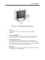
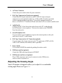
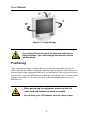
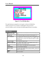
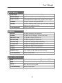
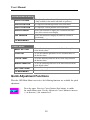
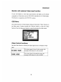
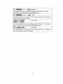
®
Displays
GDO 18 Series
18" TFT LCD Flat-panel Displays
GDO 18: 18" Flat-panel Display
GDO 18-T: GDO 18 w/ Resistive
Touchscreen
USER’S MANUAL
VER. 1 • 2002
No part of this manual may be reproduced without permission
CyberResearch , Inc.
®
www.cyberresearch.com
25 Business Park Dr., Branford, CT 06405 USA
203-483-8815 (9am to 5pm EST) FAX: 203-483-9024
©Copyright 2002
All Rights Reserved.
2002
The information in this document is subject to change without prior notice
in order to improve reliability, design, and function and does not represent
a commitment on the part of CyberResearch, Inc.
In no event will CyberResearch, Inc. be liable for direct, indirect, special,
incidental, or consequential damages arising out of the use of or inability
to use the product or documentation, even if advised of the possibility of
such damages.
This document contains proprietary information protected by copyright.
All rights are reserved. No part of this manual may be reproduced by any
mechanical, electronic, or other means in any form without prior written
permission of CyberResearch, Inc.
Trademarks
“CyberResearch,” “GDO 18-T,” and “GDO 18,” are trademarks of
CyberResearch, Inc. Other product names mentioned herein are used for
identification purposes only and may be trademarks and/or registered
trademarks of their respective companies.
• NOTICE •
CyberResearch, Inc. does not authorize any CyberResearch product for
use in life support systems, medical equipment, and/or medical devices
without the written approval of the President of CyberResearch, Inc. Life
support devices and systems are devices or systems which are intended
for surgical implantation into the body, or to support or sustain life and
whose failure to perform can be reasonably expected to result in injury.
Other medical equipment includes devices used for monitoring, data
acquisition, modification, or notification purposes in relation to life
support, life sustaining, or vital statistic recording. CyberResearch
products are not designed with the components required, are not subject
to the testing required, and are not submitted to the certification required
to ensure a level of reliability appropriate for the treatment and diagnosis of
humans.
Intentionally Blank
PREFACE
FCC Compliance Statement
Note:
This equipment has been tested and found to comply with the limits for a Class B
digital device, pursuant to Part 15 of the FCC Rules. These limits are designed to
provide reasonable protection against harmful interference when the equipment is
operated in a residential installation. This equipment generates, uses, and can
radiate radio frequency energy and, if not installed and used in accordance with
the instruction manual, may cause harmful interference to radio communications.
However, there is no guarantee that interference will not occur in a particular
installation. If this equipment does cause harmful interference to radio or
television reception, which can be determined by turning the equipment off and
on, you are encouraged to try to correct the interference by one or more of the
following measures:
• Reorient or relocate the receiving antenna.
• Increase the separation between the equipment and the receiver.
• Connect the equipment into an outlet on different fro m that to which
the receiver is connected.
• Consult CyberResearch for help.
Caution:
To comply with the limits for an FCC Class B computing device, always use
the shielded signal cord and shielded power cord supplied with this unit.
The Federal Communications Commission warns that changes or modifications
of the unit not expressly approved by the party responsible for compliance could
void the user’s authority to operate the equipment.
User’s Manual
Class B ITE (Following European Standard EN 50082-2)
Radio Frequency Interference Statement
Warning:
This is a Class B product. In a domestic environment, this product may cause
radio interference in which case the user may be required to take adequate
measures.
Canadian Doc Notice
For Class B Computing Devices
This digital apparatus does not exceed the Class B limits for radio noise
emissions from digital apparatus as set out in the Radio Interference Regulation
of the Canadian Department of Communications.
“Le présent appareil numérique n’émet pas de bruits radioélectriques dépassant
les limites applicables aux appareils numériques de la class B prescrites dans le
Règlement sur le brouillage radioélectrique édicté par le ministère des
Communications du Canada.”
iv
User’s Manual
Important Safety Instructions
Please read the following instructions carefully. This manual should be retained
for future use.
1. To clean the LCD monitor screen, first, make sure the monitor is in
the Power Off mode. Unplug the monitor from its power source before
cleaning it. Do not spray liquid cleaners directly onto the unit. Stand away
from the LCD monitor and spray cleaning solution onto a rag. Without
applying excessive pressure, clean the screen with the slightly dampened rag.
2. Do not place your LCD monitor near a window. Exposing the monitor
to rain, water, moisture or sunlight can severely damage it.
3. Do not place anything on top of the monitor-to-PC signal cord. Make sure
that the cord is placed in an area where it will not be stepped on.
4. Do not apply pressure to the LCD screen. Excessive pressure may
cause permanent damage to the display.
5. Do not remove the cover or attempt to service this unit by yourself. You may
void the warranty. Servicing of any nature should be performed only by
an authorized technician.
6. Safe storage of the LCD monitor is in a range of minus 20 to plus
65 degrees Celsius (68°F - 149°F). Storing your LCD monitor outside of this
range could result in permanent damage.
7. If any of the following occurs, immediately unplug your monitor and call
CyberResearch.
• The power or monitor-to-PC signal cord is frayed or damaged.
• Liquid has been spilled onto the monitor, or it has been exposed to rain.
v
User’s Manual
• The monitor has been dropped or the case has been damaged.
vi
User’s Manual
TABLE OF CONTENTS
CHAPTER 1 ................................................................................................................................1
The LCD Monitor.........................................................................................1
Your New LCD Monitor.................................................................................1
Unpacking..................................................................................................1
Identifying Components.................................................................................2
Adjusting the Viewing Angle..........................................................................5
Positioning...................................................................................................6
Connecting AC Power...................................................................................7
Connecting Video.................................................................................................7
Connecting the Stereo Speakers..........................................................................8
Connecting the Optional Touch Screen..............................................................................9
Power Management System........................................................................10
CHAPTER 2............................................................................................................................. 11
The Display Controls................................................................................11
The LCD Monitor’s Display Controls..........................................................11
Adjusting the Monitor’s Display...................................................................11
OSD Main Menu..........................................................................................11
APPENDIX A .......................................................................................................................... 17
Troubleshooting.........................................................................................17
Troubleshooting Procedures........................................................................17
Addendum ...................................................................................................................... 19
Technical Addendum .................................................................................................... 22
vii
User’s Manual
TABLE OF FIGURES
Figure 1-1: The LCD Monitor Panel and Controls ________________3
Figure 1-2: LCD Monitor’s Rear Ports _________________________4
Figure 1-3: Angle Settings____________________________________6
Figure 1-4: Connecting Power to the LCD Monitor________________7
Figure 1-5: Connecting the LCD Monitor to the PC _______________8
Figure 1-6: Connecting the Stereo Speakers______________________9
Figure 1-7: Connecting the Optional Touchscreen Cable___________10
Figure 2-1: The OSD Main Menu _____________________________12
viii
CHAPTER 1
The LCD Monitor
Your new LCD Monitor
Your LCD monitor has been designed to be versatile, ergonomic and user-friendly.
The LCD monitor is capable of displaying most standards, from 640 x 480 VGA to
1280 x 1024 SXGA. The digital controls located on the front panel allow the user to
easily adjust the monitor’s display parameters. The LCD monitor’s small footprint
allows you more room in your workspace for other peripherals. Lightweight and
compact, the LCD monitor is the perfect solution for all type of users. You can use
the LCD monitor for everything from making business presentations to playing
computer games. The two stereo speakers allow you to further expand your
computer’s multimedia capabilities by connecting your computer’s Audio out port to
the LCD monitor’s Audio in port. If you have a complete workstation, the LCD
monitor has the additional feature of an optional wall-mountable and VESA compliant
arm-mounted bracket for added convenience.
The architecture of the LCD monitor incorporates an LCD panel that produces a clear
display without radiation emission, limiting health concerns. With its low power
consumption, the LCD monitor helps you reduce your power bill.
Unpacking
Before you unpack your LCD monitor, prepare a suitable workspace for the
monitor and computer. You need a stable, level and clean surface near a wall outlet.
Even though the LCD monitor uses very little power, you should put it in a location,
which allows sufficient airflow to ensure that the monitor and your computer do
not become too hot. Set up your LCD monitor so that the panel doesn’t face a
window where sunlight often comes in. The glare caused by sunlight reflecting off
the LCD monitor’s screen will make it difficult to see.
1
User’s Manual
Using a computer for an extended period of time with a poor workstation
set-up and incorrect working habits can cause health problems. The
science of ergonomics studies the relationship between health and a
suitable working environment. There is a section on ergonomics at the
end of this chapter. For more information on ergonomics, contact your
nearest computer bookstore, or local library. The Internet also has
information on this and other subjects.
After you unpack your LCD monitor; make sure the following items are included in
the box and in good condition:
• LCD Monitor
• Monitor-to-PC Analog Signal Cable (15-pin)
• Monitor-to-PC Digital Signal Cable (24-pin)
• USB Cable (optional)
• S-Terminal Video Cable (optional)
• Stereo Jack Audio Cable
• Power Cord
• This User’s Manual
If you find that any of these items are missing or appear damaged, contact CyberResearch
immediately. Do not throw away the packing material or shipping carton in case you
need to ship or store the monitor in the future.
Identifying Components
The LCD monitor has been designed to provide easy access to all controls and
peripheral ports. The following figures will help you identify the LCD monitor’s
controls and ports.
The LCD Monitor — Front View
2
User’s Manual
Figure 1-1: The LCD Monitor Panel and Controls
1.
LCD Screen
The RGB LCD monitor screen is capable of producing most display
standards.
2.
Function Control Buttons
These two buttons allow you to select one of the control functions. Press
either the upper or lower control button to scroll through the menu items.
3.
Adjustment Control Buttons
These two buttons allow you to adjust the selected control function to
accommodate your specific working environment. Press the upper button to
increase the setting of the selected control function and press the lower button
to decrease the setting of the selected control function.
4.
Menu button
Push the Menu button to pop u p the OSD (On-Screen Display) menu. Push
the button again to close the OSD menu.
3
User’s Manual
5.
Power-On Indicator
This LED indicator lights when the power is on. The LED indicator will
blink when the LCD monitor is in Power Saving mode.
6.
Monitor Swivel Base
The monitor swivel base supports the LCD panel and changes the monitor
angles.
7.
Stereo Speakers
You can connect your PC’s Audio Out port to the LCD monitor’s Audio In
port and listen to your PC’s audio output with these speakers.
The LCD Monitor — Rear View
Figure 1-2: LCD Monitor’s Rear Ports
1.
Input Signal Ports
The monitor has one 15-pin D-sub VGA connector and one 24-pin DVI
connector, the 24-pin DVI connector is for Digital signal if your PC has
a digital graphic card.
4
User’s Manual
2.
AC Power Connector
Connect the power cable to this AC power connector.
3.
PS/2-Type Connector for Touchscreen (optional)
Connect this PS/2 6-pin connector to your PC’s RS-232 9-pin serial port
connector to use the optional touchscreen. A PS/2 to RS-232 cable is provided
with the optional touchscreen package. To install the optional touchscreen
driver, see the ELO 18" Touchscreen Guide on the driver CD, or contact CyberResearch
4.
Audio Line In
Connect your PC’s Line Out to this jack to listen to the PC’s audio through
the LCD monitor’s stereo speakers. (You can also connect your CD-ROM’s
Line Out to this jack.)
5.
Stereo Headphone Jack
You can connect stereo headphones or powered external speakers to this jack
and listen to your PC’s audio output.
6.
PS/2-Type Connector for A/V Connection (optional)
You can connect this 5-pin connector to the TV signal source (NTSC or PAL).
A PS/2 to AV terminal (or S-terminal) cable is provided.
7.
Power Switch
You can turn ON/OFF the monitor by pushing this rocker switch.
8.
USB Upstream Port (optional)
Connect the USB cable from this port to PC HOST.
9.
USB Downstream Ports (x4, optional)
These USB connectors can be used to connect to other USB devices,
such as a mouse, keyboard, etc.
Adjusting the Viewing Angle
Your LCD monitor is designed to allow you to adjust it to a comfortable
viewing angle. Please see Figure 1-3.
5
User’s Manual
Figure 1-3: Angle Settings
Do not force the monitor past its maximum extension in
either direction. You could damage the monitor and the
monitor stand.
Positioning
Take a moment to prepare a suitable place to set up your workstation. You need a
stable, flat dust-free surface with good ventilation. Even though the LCD monitor has
been designed using components that don’t use much power, they still generate quite
a bit of heat. Set up your LCD monitor so that the screen doesn’t face a window where
sunlight often comes in. The glare caused by reflected sunlight makes the screen
difficult to see.
• When positioning the equipment, make sure that the
main ports and sockets are easily accessible.
• Do not place your LCD monitor close to a heat source.
6
User’s Manual
• Do not place the LCD monitor in direct sunlight or near
a window. Moisture and direct sunlight exposure can
be seriously damaging.
Connecting AC Power
Please refer to the following instructions for connecting AC power to the LCD
monitor.
1.
Plug the female end of the power cable into the AC power connector. Plug
the male end of the power cord into a wall socket. The plug on the power
cable will vary according to the electrical standard in your area. Please refer
to Figure 1-4.
Figure 1-4: Connecting Power to the LCD Monitor
Connecting Video
1.
Turn off your PC and the LCD monitor before connecting your LCD monitor
to the computer.
2.
Connect one end of the VGA signal cable to the PC’s D-sub VGA port
and the other end to the monitor VGA port. Please refer to Figure 1-5.
7
User’s Manual
Figure 1-5: Connecting the LCD Monitor to the PC
3.
If your PC has a graphic card with a 24-pin DVI connector, you should
connect it with the digital 24-pin DVI signal cable.
4.
Make sure the signal cable head is securely connected to the VGA port
of your PC. Tighten the connecting screws to ensure a secure connection.
5.
Turn on your computer and LCD monitor.
If both analog (15-pin D-sub VGA) and digital (24-pin DVI) input ports
are connected at the same time, the signal input can be selected with
the OSD (On-Screen Display) menu. Please go to the next chapter for
details.
Connecting the Stereo Speakers
Please refer to the following instructions for connecting the LCD monitor’s stereo
speakers.
1.
Connect the 1.5M sound cable to the Line out of your PC’s audio card.
8
User’s Manual
2.
Connect the other end of the 1.5M sound cable to the LCD monitor’s line-in
jack. Please refer to Figure 1-6.
Figure 1-6: Connecting the Stereo Speakers
3.
You can adjust the sound volume of the stereo speakers by using the speaker
volume control function on the OSD (On-Screen Display). Please refer to the
next chapter for details.
Connecting the Optional Touchscreen
Your LCD monitor has an optional touchscreen feature. If your LCD monitor has this
feature, connect the LCD monitor’s PS/2 connector to your PC’s 9-pin RS-232 serial
port to enable the touchscreen.
1.
Connect the PS/2 connector end of the PS/2 to RS-232 cable provided with
the optional touchscreen package to the PS/2 mini-DIN port at the back
of the LCD monitor. Please refer to Figure 1-7.
9
User’s Manual
Figure 1-7: Connecting the Optional Touchscreen Cable
2.
Connect the D-sub 9-pin RS-232 connector end of the PS/2 to RS-232 cable
provided with the optional touchscreen package to the 9-pin RS-232 serial
port at the back of your PC. Please refer to Figure 1-7.
3.
Install the Touchscreen drivers to your PC.
4.
Following the Touchscreen driver guide to align your touchscreen
positioning.
Power Management System
The LCD monitor complies with the VESA DPMS (version 1.0p) power management
proposal. The VESA DPMS proposal provides four phases of power saving modes by
detecting the horizontal or vertical sync signal. When the LCD monitor is in power
saving mode or detects an incorrect timing, the monitor screen will go blank, and the
power LED indicator will start to blink.
10
CHAPTER 2
The Display Controls
The LCD Monitor Display Controls
This chapter covers the LCD monitor’s On-Screen Display (OSD). Using the OSD
you can adjust the contrast, brightness, display position, display clarity, and color
temperature, etc. You can also adjust the stereo speaker volume and set OSD
parameters. Please read this chapter carefully to get the most out of your LCD
monitor.
Adjusting the Monitor’s Display
The LCD monitor features an intuitive, menu-driven, On-Screen Display (OSD). You can
access the OSD any time that the PC is powered on. If the PC is in a power save mode
or is powered off, the OSD is inaccessible.
The OSD makes adjusting display settings quick and simple. Use the MENU button to
access the OSD and the Function button to scroll through the menu items. Use the
Adjustment buttons to make changes to the selected menu item. Please refer to
Figure 2-1.
OSD Main Menu
To access the OSD Main Menu, simply press the MENU button. The following
screen will appear.
11
User’s Manual
Figure 2-1: The OSD Main Menu
The control functions are grouped into seven categories as shown on the Main Menu.
Continue pressing the Function buttons to scroll through the menu item. Press the
Adjustment buttons to enter the sub-menu of each function group. Each item is covered below.
Main Menu
BASIC SETTING
To control the contrast, brightness, video level, and gamma,
etc.
POSITION
To control the display size, position, clock and phase, etc.
AUTO-ADJUST
To automatically adjust the picture quality and alignment. It is
recommended to use this function in the windows (This
function does not work in the interlaced modes) or similar
environments.
COLOR TEMP.
To control the display colors.
MISCELLANEOUS
To control audio volume, OSD positions and to give
information of the Display modes.
VIDEO
For S-video or CVBS input mode selection (optional)
LANGUAGE
To select different languages.
INPUT PORT
RESET
To select input signal sources between PORT1 (VGA) and
PORT2 (Digital DVI).
To set the display parameters to the factory-set default values.
EXIT
Exit OSD Menu.
12
User’s Manual
Basic Setting
CONTRAST
To adjust the contrast level of the display.
BRIGHTNESS
To adjust the brightness level of the display.
VIDEO LEVEL
To fine tuning the matching input signal voltage level.
Perform this function whenever the graphics card is changed.
To select a suitable color representation.
GAMMA
FRAME
TO MAIN MENU
To select different border colors (up to 64 colors) when the
display is not in full-screen size.
Return to Main Menu.
Position
CLOCK
To adjust the display pixel alignment.
PHASE
To adjust the screen display for focus and clarity.
DEFAULT SIZE
To expand the display to full screen.
NATIVE SIZE
To adjust the display to original size.
H-POSITION
To adjust the display position horizontally.
V-POSITION
To adjust the display position vertically.
H-SIZE
To adjust the display size horizontally.
V-SIZE
To adjust the display size vertically.
GRAPH/TEXT
To select either Graph or Text expansion method.
Only available in 720 x 400/640 x 480 resolutions.
Return to Main Menu.
TO MAIN MENU
Color Temp. Menu
9300
To select the color temperature at CIE coordinate 9300º
6500
To select the color temperature at CIE coordinate 6500º
USER
Select this option to enable the “User Color” field. Individual
R, G, B levels can be adjusted.
TO MAIN MENU
Return to Main Menu.
13
User’s Manual
Miscellaneous Menu
OSD H-POSITION
To adjust the audio volume of the monitor’s speakers.
(Only available in the models with built-in speakers.)
To adjust the horizontal position of the OSD menu.
OSD V-POSITION
To adjust the vertical position of the OSD menu.
DISPLAY MODE
Select this function to display the resolution and frame
rate of the current screen display.
Select this function to display the firmware version of
the monitor.
Return to Main Menu.
AUDIO VOLUME
F/W VERSION
TO MAIN MENU
Reset Menu
BASIC SETTING
POSITION
To set the function parameters in the Basic Setting Menu
to the default values.
To set the function parameters in the Position Menu to
the default values.
COLOR TEMP.
To set the function parameters in the Color Temp. Menu to
the default values.
MISCELLANEOUS
ALL FUNCTIONS
To set the function parameters in the Miscellaneous Menu
tto he default values.
To set all function parameters to the default values.
TO MAIN MENU
Return to Main Menu.
Quick Adjustment Functions
When the OSD Main Menu is not active, the following functions are available for quick
adjustment.
Press the upper Function Control button (first button) to enable
the small contrast icon. Use the Adjustment Control button to increase
(+) or decrease (-) the contrast level.
14
User’s Manual
Press the lower Function Control button (second button) to enable
the small Brightness icon. Use the Adjustment Control button
to increase (+) or decrease (-) the brightness level.
Press the upper Adjustment Control button (third button) to enable
the small volume icon. Use the Adjustment Control button to increase
(+) or decrease (-) the volume.
Press the lower Adjustment control button (fourth buttons) to enable
the small port icon. Press it again to switch to the other DVI (PORT2)
and close the icon.
1.
No Signal coming.
When the monitor is ON and there is no video signal received,
the following message will be displayed.
NO SIGNAL COMING…
CHECK SIGNAL CABLE
MONITOR WILL ENTER
POWER SAVING!!!!
2.
Signal out of monitor’s supported range.
When the frequency range is out of the monitor specifications,
the following message will be displayed.
SIGNAL OVER RANGE!
PRESS FUN/ADJ KEY
FUN? H-POSITION
ADJ? V-POSITION
When the signal is out of monitor frequency range, the screen display
will not be centered and the warning message appears. Users can pan
the display picture with the Function Control and Adjustment Control
buttons. Then, user’s can see the display and change the frequency range.
15
APPENDIX A
Troubleshooting
Troubleshooting Procedures
This LCD Monitor was pre-adjusted in the factory with standard VGA timing. Due to
output timing differences among various VGA cards, you may initially experience an
unstable or unclear display when a new display mode or new VGA card is selected.
This LCD Monitor Supports Multiple VGA Modes. Refer to Addendum
for a listing of the factory preset modes supported by this LCD Monitor.
PROBLEM: Display is Unclear and Unstable
To stabilize and clarify your display, follow this procedure in this order:
1.
It’s best to adjust the display on a screen displaying vertical
lines. In Windows, load a wallpaper bitmap that has vertical
lines in it. (Or you can the select window shut down screen)
2.
After you have the wallpaper loaded, open the OSD and select
the “Clock” function. Press the top (or bottom) Adjustment
Control button and continue pressing the button until you see
vertical dark and light lines across the screen.
3.
When you can see distinct light and dark vertical bands,
stop pressing the Adjustment Control button. Now press the
opposite (top or bottom) Adjustment Control button. The
vertical dark and light bands will decrease in number. Keep
pressing the button until the distinct bands disappear and you
have a clear display.
4.
Next press the Function Control button to choose the “Phase”
function. The Phase will adjust the horizontal display. Press the
top (or bottom) Adjustment Control button and you will see
17
User’s Manual
horizontal dark and light lines appear. The number of lines
increases as you press the button. Now press the bottom (or top)
Adjustment Control button until the lines disappear and you
have a clear display.
PROBLEM: There is no LCD Display
If there is no display on the LCD, please perform the following steps:
1.
Make sure that the power indicator on the LCD monitor is lit,
all connections are secure, and the system is running on the
correct timing. Refer to the Addendum for information on
timing.
2.
Turn off the LCD monitor and then turn it back on again. Press
the upper Function Control button (refer to Chapter 2) once and
then press either the upper or lower Adjustment Control button
several times. If there is still no display, press the other
Adjustment Control button several times.
3.
If step 2 doesn’t work, connect your PC system to another
external CRT monitor. If your PC system functions properly
with a CRT monitor but it does not function with the LCD
monitor and the LCD monitor’s power LED is blinking, the
output timing of the PC’s VGA card may be out of the LCD’s
synchronous range. Please change to an alternate mode listed in
Addendum or replace the VGA card and repeat steps 1 and 2.
4. If the PC (or Notebook PC) doesn’t function with the CRT
monitor either, check BIOS to see if there is a Simultaneous
Display setting under the display mode item. Set the BIOS
display mode to Simultaneous Display or CRT and try again. If
there is still no display, then there may be a problem with your
system. Contact technical support for assistance.
5.
If the power LED is not lit, check to see if the AC power
connector is securely connected. If the power LED is not lit,
please contact technical support for assistance.
18
19
20
21
22
23
24
25
Intentionally Blank
26
Product Service
Diagnosis and Debug
CyberResearch, Inc. maintains technical support lines staffed by experienced
Applications Engineers and Technicians. There is no charge to call and we will
return your call promptly if it is received while our lines are busy. Most problems
encountered with data acquisition products can be solved over the phone. Signal
connections and programming are the two most common sources of difficulty.
CyberResearch support personnel can help you solve these problems, especially
if you are prepared for the call.
To ensure your call’s overall success and expediency:
1)
2)
3)
4)
5)
6)
Have the phone close to the PC so you can conveniently and quickly take
action that the Applications Engineer might suggest.
Be prepared to open your PC, remove boards, report back-switch or
jumper settings, and possibly change settings before reinstalling the
modules.
Have a volt meter handy to take measurements of the signals you are
trying to measure as well as the signals on the board, module, or power
supply.
Isolate problem areas that are not working as you expected.
Have the source code to the program you are having trouble with available
so that preceding and prerequisite modes can be referenced and
discussed.
Have the manual at hand. Also have the product’s utility disks and any
other relevant disks nearby so programs and version numbers can be
checked.
Preparation will facilitate the diagnosis procedure, save you time, and avoid
repeated calls. Here are a few preliminary actions you can take before you call
which may solve some of the more common problems:
1)
2)
3)
4)
Check the PC-bus power and any power supply signals.
Check the voltage level of the signal between SIGNAL HIGH and SIGNAL
LOW, or SIGNAL+ and SIGNAL– . It CANNOT exceed the full scale range
of the board.
Check the other boards in your PC or modules on the network for address
and interrupt conflicts.
Refer to the example programs as a baseline for comparing code.
27
Intentionally Blank
28
Warranty Notice
CyberResearch, Inc. warrants that this equipment as furnished will be free from
defects in material and workmanship for a period of one year from the confirmed
date of purchase by the original buyer and that upon written notice of any such
defect, CyberResearch, Inc. will, at its option, repair or replace the defective item
under the terms of this warranty, subject to the provisions and specific exclusions
listed herein.
This warranty shall not apply to equipment that has been previously repaired or
altered outside our plant in any way which may, in the judgment of the manufacturer,
affect its reliability. Nor will it apply if the equipment has been used in a manner
exceeding or inconsistent with its specifications or if the serial number has been
removed.
CyberResearch, Inc. does not assume any liability for consequential damages as a
result from our products uses, and in any event our liability shall not exceed the
original selling price of the equipment.
The equipment warranty shall constitute the sole and exclusive remedy of any Buyer
of Seller equipment and the sole and exclusive liability of the Seller, its successors
or assigns, in connection with equipment purchased and in lieu of all other
warranties expressed implied or statutory, including, but not limited to, any implied
warranty of merchant ability or fitness and all other obligations or liabilities of seller,
its successors or assigns.
The equipment must be returned postage prepaid. Package it securely and insure it.
You will be charged for parts and labor if the warranty period has expired.
Returns and RMAs
If a CyberResearch product has been diagnosed as being non-functional, is visibly
damaged, or must be returned for any other reason, please call for an assigned
RMA number. The RMA number is a key piece of information that lets us track and
process returned merchandise with the fastest possible turnaround time.
PLEASE CALL FOR AN RMA NUMBER!
Packages returned without an RMA number will be refused!
In most cases, a returned package will be refused at the receiving dock if its
contents are not known. The RMA number allows us to reference the history of
returned products and determine if they are meeting your application’s requirements.
When you call customer service for your RMA number, you will be asked to provide
information about the product you are returning, your address, and a contact person
at your organization.
Please make sure that the RMA number is prominently
displayed on the outside of the box.
• Thank You •
29
Intentionally Blank
30
CyberResearch, Inc.
25 Business Park Drive
Branford, CT 06405 USA
P: (203) 483-8815; F: (203) 483-9024
www.cyberresearch.com