1
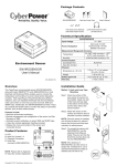
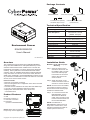
Package Contents
Cy
be
Re
liab
rPo
w
ility
. Qu
alit
y. Va
er
R
lue
.
Us
er's
ENVIROSENSOR
Hook and Loop Tape
Flat Head Screw (M3x20)
with Plastic Nylon Anchor
Ma
nual
User’s Manual
CAT5 RJ45 Ethernet Cable
(10 feet/3.05 m)
Technical Specification
Input Voltage
ENVIROSENSOR
Power Dissipation
Environment Sensor
ENVIROSENSOR
User’s Manual
K01-0000207-00
Measurement Range and Accuracy
32-158℉ with accuracy ± 1.8℉/
Temperature
0-70℃ with accuracy ± 1℃
Humidity
10-90 RH with accuracy ± 2%
Communication
Connection Port
RJ45 Port
Input Dry Contact
4
Physical
2.32 x 1.77 x 1.14 inches/
Dimensions (L x W x H)
59 x 45 x 29 mm
Weight
1.46 oz /41.5 g
Safety Approvals
FCC Class B, CE, C-Tick
Warranty
3 Year Limited
Overview
Installation Guide
The CyberPower environmental sensor (ENVIROSENSOR)
along with select SNMP/HTTP cards (RMCARDXXX) or most
Switched and Monitored PDUs enables users to monitor the
temperature and humidity of a server closet and/or datacenter
remotely. With CyberPower's PowerPanel Business Edition
software, users can establish thresholds that will automatically
notify users when an event has occurred via email, SMS and
SNMP traps. Additionally, the ENVIROSENSOR provides 4 input
dry contacts that enable users to monitor the status of connected
devices, such as door switch sensors.
Method 1- Hook and Loop Tape
Mounting
Features include:
• Real time environment monitoring
• Remote management and configuration of the sensor via Web
Browsers or NMS
• Automatic events notification via email, SMS and SNMP traps
• 4 input dry contacts application interface provided
• Displays the name and location of the sensor and
connected devices
A
Product Features
A. LED
B. Input Dry Contact 1-4
C. Common Connection
D. RJ45 Port
(connect to RMCARD/PDU)
STATUS
B
D
NOTE: Please refer to Appendix
for Input Dry Contact Application.
1
2
3
C
7V - 28V
Halt mode 72 mW/
Normal mode 110 mW
(Default 12V input)
Step 1. Clean the surface of the
area where the sensor will
be installed. Apply one side
of the hook and loop tape
to the bottom of the sensor
and the other side to the
sensor location.
Step 2. Attach the sensor on the
surface and hold for about 5
seconds to ensure cohesion.
NOTE: Once the sensor is installed,
you will want to leave it in place to
ensure the the hook and loop tape
maintains its adhesiveness.
Step 3. To connect the sensor with
RMCARD/PDU, use the
attached RJ45 Ethernet
Cable. Plug one end into the
RJ45 Port and the other end
into the RMCARD/PDU.
NOTE: If the distance of
RMCARD/PDU and the sensor is
longer than 10 feet/3.05 m, use a
standard RJ45 Ethernet Cable as
needed (max 50 feet/15 m).
4 COM
Universal
DATA
Copyright © 2011 CyberPower Systems, Inc.
Link
RX/TX
RMCARD203