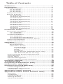
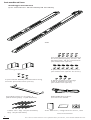
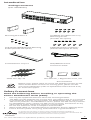
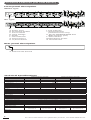
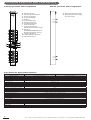
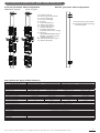
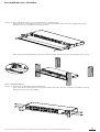
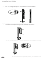
1
User Manual
Power
Distribution
Unit
Table of Contents
Model List............................................................1
Introduction.........................................................1
Package Contents........................................................ 1
For 1U Series......................................................... 1
For 0U Series......................................................... 2
For 2U Series......................................................... 3
Safety Precautions...................................................... 3
Proruct Features......................................................... 4
1U 15A Series........................................................ 4
Technical Specifications........................................ 4
1U 20A Series........................................................ 5
Technical Specifications........................................ 5
0U 15A Series........................................................ 6
Technical Specifications........................................ 6
0U 20A Series........................................................ 7
Technical Specifications........................................ 7
0U 30A Series........................................................ 8
Technical Specifications........................................ 8
2U Series............................................................... 9
Technical Specifications........................................ 9
Installation Guide.................................................10
Horizontal Installation................................................ 10
For 1U Model........................................................ 10
For 2U Model........................................................ 11
Vertical Installation ................................................... 13
For 1U Model........................................................ 13
For 0U Model with Bracket................................... 13
For 0U Model with Keyhole Mount...................... 15
Electrical Installation.................................................. 15
Network Installation................................................... 16
Operation.............................................................17
Metered Readout...................................................... 17
Basic Operation..................................................... 17
PDU Status Screen................................................ 17
Current Level................................................. 17
Input Voltage................................................. 17
Power............................................................ 17
IP Address..................................................... 17
Outlet Control (switched series only)........... 17
LED Reversal (0U series only)........................ 17
Environmental Monitoring (optional)....................... 18
LED Indicators............................................................ 18
Device Reset.............................................................. 18
Remote Management............................................... 18
Unattended/Automatic Shutdown............................ 19
Firmware Upgrade...............................................19
Troubleshooting...................................................20
Frequently Ask Questions (FAQ)...........................20
Conformance Approvals.......................................20
Customer Service & Warranty..............................21
Product Registration.................................................. 21
CyberPower International......................................... 21
Limited Warranty...................................................... 21
Appendix A-Hyper Terminal.................................22
Appendix B-Power Device Network Utility...........23
Overview................................................................... 23
Installation................................................................. 23
Launch Program........................................................ 24
Getting Started.......................................................... 24
Advanced Settings..................................................... 25
Model List
1U Switched Series
0U Monitored Series
PDU15SW8FNET
PDU15SWHVIEC8FNET
PDU20SW8FNET
PDU20SWT8FNET
PDU20SWHVIEC8FNET
PDU15MV16FNET
PDU20MVT24FNET
PDU20MVHVT24FNET
PDU30MVT24FNET
PDU30MVHVT24FNET
1U Monitored Series
2U Switched Series
PDU15M8FNET
PDU15MHVIEC8FNET
PDU20M8FNET
PDU20MT8FNET
PDU20MHVIEC8FNET
PDU30SWT16FNET
PDU30SWHVT16FNET
2U Monitored Series
PDU30MT16FNET
PDU30MHVT16FNET
0U Switched Series
PDU15SWV16FNET
PDU20SWVT24FNET
PDU20SWVHVT24FNET
PDU30SWVT24FNET
PDU30SWVHVT24FNET
Introduction
Package Contents
(For 1U Series)
6 (M3x6) Cord Retention
Tray Mounting Screws
(Includes two spares)
PDU
6 (M5x12) Screws / 6 Washers
(Includes two spares for each)
Mounting Bracket: 2 short & 2 long
RJ45/DB9 Serial Port
Connection Cable
10 (Flat Head M4x8) Bracket Mounting
Screws (Includes two spares)
Power Cord 10 feet,
IEC-320 C13/IEC-320 C14
(PDU15SWHVIEC8FNET/
PDU15MHVIEC8FNET Model Only)
Cord Retention Tray
Power Cord 10 feet,
IEC-320 C19/ IEC-320 C20
(PDU20SWHVIEC8FNET/
PDU20MHVIEC8FNET Model Only)
Cybe
rPow
er
Reliab
R
ility. Qualit
y. Value.
User's
Cable Ties / Qty. 10
Manual
Registration
Card
User Manual / Registration Card / CD
Documentation
For more information on CyberPower products, visit www.CPSww.com
1
Introduction
Package Contents
(For 0U Series 16 Outlets/24 Outlets)
PDU
Cord Retention Tray Mounting
Screws (M3x6)/Qty. 10 for 16
Outlets/Qty. 14 for 24 Outlets
(Includes two spares)
Mounting Brackets x 2
6 (M5x12) Screws/6 Washers
(Includes two spares for each)
6 (Flat Head M4x4) Bracket Mounting
Screws (Includes two spares)
2 Keyhole Mounting Pegs
with 4 (M4x5) Screws
(Includes two spares)
Cord Retention Trays Qty. 2
(16 Outlets)/Qty. 3 (24 Outlets)
RJ45/DB9 Serial Port
Connection Cable
Cybe
rPow
er
Reliab
R
ility. Qualit
y. Value.
User's
Cable Ties: Qty. 20 (16 Outlets)
Qty. 30 (24 Outlets)
2
Manual
Registration
Card
User Manual / Registration Card / CD
Documentation
For more information on CyberPower products, visit www.CPSww.com
Introduction
Package Contents
(For 2U Series)
PDU
Mounting Brackets x 2
10 (M3x6) Cord Retention Tray
Mounting Screws
(Includes two spares)
10 (Flat Head M4x8) Bracket Mounting
Screws (Includes two spares)
6 (M5x12) Screws / 6 Washers
(Includes two spares for each)
Cord Retention Trays x2
RJ45/DB9 Serial Port
Connection Cable
Cybe
rPow
er
Reliab
R
ility. Qualit
y. Value.
User's
Cable Ties: Qty. 20
Manual
Registration
Card
User Manual / Registration Card / CD
Documentation
Check
Before using, please check to ensure the package contains all the
items shown above. If there are missing parts, please contact
your local CyberPower (refer to CyberPower International P.21)
for technical support.
Safety Precautions
Read the following before installing or operating the
Power Distribution Units (PDU):
•
•
•
•
•
Use only the supplied hardware to attach the mounting brackets.
The PDU must be plugged into a three-wire, grounded outlet on a circuit that
is protected by a fuse or circuit breaker. For PDU15xxxxx series, please use
15A circuit protector. For PDU20xxxxx series, please use 20A circuit protector.
For PDU30xxxxx series, please use 30A circuit protector. Connection to any
other type of power outlet may result in a shock hazard.
Do not use extension cords or adapters with this PDU.
Never install a PDU, or associated wiring or equipment, during a lightning storm.
Ensure that the power cord, plug, and socket are in good condition.
To prevent the risk of fire or electric shock, this PDU should be installed in a
temperature and humidity controlled indoor area free of conductive contaminants. Do
not install this PDU where excessive moisture or heat is present.
For more information on CyberPower products, visit www.CPSww.com
3
Product Features (1U 15A Series)
Front panel description
NEMA Type
IEC Type
A. Power Cord
B. AC Output Outlets
C. Current Level
D. Input Voltage
E. Power
F. Load Indicator
G. Ethernet Port
H. Tx/Rx Indicator
I. Link Indicator
J. Outlet Indicator
(switched series only)
K. Serial/ ENVIROSENSOR Port
(RJ45 modular port)
L. Select Button
M.PDU Status Screen
N. Reset Button
Rear panel description
A
A
A. External Site Ground
Technical Specifications
Switched Series (1U 15A)
Model Name
Monitored Series (1U 15A)
PDU15SW8FNET
PDU15SWHVIEC8FNET
PDU15M8FNET
PDU15MHVIEC8FNET
100-120V
200-240V
100-120V
200-240V
Input
Nominal Voltage
Frequency
Derated Input Current
50/60Hz
12A
12A(UL)/10A(CE)
12A
12A(UL)/10A(CE)
Plug Type
NEMA 5-15P
IEC-320 C14
NEMA 5-15P
IEC-320 C14
Power Cord Type
SR (14 AWG)
Socket
SR (14 AWG)
Socket
Power Cord Length
12 ft/3.65 m
10 ft/3.05 m
12 ft/3.65 m
10 ft/3.05 m
100-120V
200-240V
100-120V
200-240V
12A
12A(UL)/10A(CE)
12A
12A(UL)/10A(CE)
NEMA 5-15R
IEC-320 C13
NEMA 5-15R
IEC-320 C13
Output
Nominal Voltage
Derated Output Current
Outlet Type
Outlet Number
8
Networking
Protocol Support
TCP/IP, UDP, DHCP, SNMP, HTTP
Connectivity
RJ45
Physical
Dimension (HxWxD)
1.75" x 17.05" x 4.41"/44mm x 433mm x 112mm
Environmental
Humidity
0 to 95% Non-condensing
Altitude
14700 ft/4500 m
32oF to 113oF /0oC to 45oC
Temperature
Safety Approvals
Certifications
UL 60950-1
CSA C22.2
FCC Class A
UL 60950-1
CSA C22.2
CE, FCC Class A
UL 60950-1
CSA C22.2
FCC Class A
UL 60950-1
CSA C22.2
CE, FCC Class A
Warranty
Product Warranty
4
3 years
For more information on CyberPower products, visit www.CPSww.com
Product Features (1U 20A Series)
Front panel description
NEMA Type
IEC Type
A. Power Cord
B. AC Output Outlets
C. Current Level
D. Input Voltage
E. Power
F. Load Indicator
G. Ethernet Port
H. Tx/Rx Indicator
I. Link Indicator
J. Outlet Indicator
(switched series only)
K. Serial/ ENVIROSENSOR Port
(RJ45 modular port)
L. Select Button
M.PDU Status Screen
N. Reset Button
Rear panel description
A
A
A. External Site Ground
Technical Specifications
Switched Series (1U 20A)
Model Name
PDU20SW8FNET
PDU20SWT8FNET
Monitored Series (1U 20A)
PDU20M8FNET
PDU20SWHVIEC8FNET
PDU20MT8FNET
PDU20MHVIEC8FNET
Input
Nominal Voltage
100-120V
200-240V
Frequency
100-120V
Derated Input Current
Plug Type
200-240V
50/60Hz
16A
NEMA 5-20P
NEMA L5-20P
NEMA 5-20P
IEC-320 C20
NEMA L5-20P
IEC-320 C20
Power Cord Type
SR (12 AWG)
Socket
SR (12 AWG)
Socket
Power Cord Length
12 ft/3.65 m
10 ft/3.05 m
12 ft/3.65 m
10 ft/3.05 m
100-120V
200-240V
100-120V
200-240V
NEMA 5-20R
IEC-320 C13
Output
Nominal Voltage
Derated Output Current
Outlet Type
16A
NEMA 5-20R
IEC-320 C13
Outlet Number
8
Networking
Protocol Support
TCP/IP, UDP, DHCP, SNMP, HTTP
Connectivity
RJ45
Physical
Dimension (HxWxD)
1.75" x 17.05" x 4.41"/44mm x 433mm x 112mm
Environmental
Humidity
0 to 95% Non-condensing
Altitude
14700 ft/4500 m
32oF to 113oF /0oC to 45oC
Temperature
Safety Approvals
Certifications
UL 60950-1
CSA C22.2
FCC Class A
UL 60950-1
CSA C22.2
CE, FCC Class A
UL 60950-1
CSA C22.2
FCC Class A
UL 60950-1
CSA C22.2
CE, FCC Class A
Warranty
Product Warranty
3 years
For more information on CyberPower products, visit www.CPSww.com
5
Product Features (0U 15A Series)
Front panel description
Rear panel description
A. Power Cord
B. AC Output Outlets
C. Current Level
D. Input Voltage
E. Power
F. Load Indicator
G. Ethernet Port
H. Tx/Rx Indicator
I. Link Indicator
J. Outlet Indicator
(switched series only)
K. Serial /
ENVIROSENSOR Port
(RJ45 modular port)
L. Select Button
M. PDU Status Screen
N. Reset Button
A. Bracket Screw Hole
B. Keyhole Mount Peg
Screw Hole
B
A
A
B
Technical Specifications
Model Name
Switched Series (0U 15A)
Monitored Series (0U 15A)
PDU15SWV16FNET
PDU15MV16FNET
Input
Nominal Voltage
100-120V
Frequency
50/60Hz
Derated Input Current
12A
Plug Type
NEMA 5-15P
Power Cord Type
SR (14 AWG)
Power Cord Length
10 ft/3.05 m
Output
Nominal Voltage
Derated Output Current
Outlet Type
Outlet Number
100-120V
12A
NEMA 5-15R
16
Networking
Protocol Support
Connectivity
TCP/IP, UDP, DHCP, SNMP, HTTP
RJ45
Physical
Dimension (HxWxD)
49" x 2.20" x 1.75"/1245mm x 56mm x 44mm
Environmental
Humidity
Altitude
Temperature
0 to 95% Non-condensing
14700 ft/4500 m
32oF to 113oF /0oC to 45oC
Safety Approvals
Certifications
UL 60950-1, CSA C22.2, FCC Class A
Warranty
Product Warranty
6
3 years
For more information on CyberPower products, visit www.CPSww.com
Product Features (0U 20A Series)
Front panel description
NEMA Type
Rear panel description
IEC Type
B
A. Power Cord
B. AC Output Outlets
C. Current Level
D. Input Voltage
E. Power
F. Load Indicator
G. Ethernet Port
H. Tx/Rx Indicator
I. Link Indicator
J. Outlet Indicator
(switched series only)
K. Serial /
ENVIROSENSOR Port
(RJ45 modular port)
L. Select Button
M. PDU Status Screen
N. Reset Button
A
A. Bracket Screw Hole
B. Keyhole Mount Peg
Screw Hole
A
B
Technical Specifications
Switched Series (0U 20A)
Model Name
Monitored Series (0U 20A)
PDU20SWVT24FNET
PDU20SWVHVT24FNET
PDU20MVT24FNET
PDU20MVHVT24FNET
100-120V
200-240V
100-120V
200-240V
NEMA L5-20P
NEMA L6-20P
Input
Nominal Voltage
Frequency
50/60Hz
Derated Input Current
Plug Type
16A
NEMA L5-20P
NEMA L6-20P
Power Cord Type
SR (12 AWG)
Power Cord Length
10 ft/3.05 m
Output
Nominal Voltage
100-120V
200-240V
Derated Output Current
Outlet Type
Outlet Number
100-120V
200-240V
16A
NEMA 5-20R
IEC-320 C13*21/
IEC-320 C19*3
NEMA 5-20R
IEC-320 C13*20/
IEC-320 C19*4
24
21+3
24
20+4
Networking
Protocol Support
Connectivity
TCP/IP, UDP, DHCP, SNMP, HTTP
RJ45
Physical
Dimension (HxWxD)
66.53" x 2.20" x 1.75"/1690mm x 56mm x 44mm
Environmental
Humidity
Altitude
Temperature
0 to 95% Non-condensing
14700 ft/4500 m
32oF to 113oF /0oC to 45oC
Safety Approvals
Certifications
UL 60950-1, CSA C22.2, FCC Class A
Warranty
Product Warranty
3 years
For more information on CyberPower products, visit www.CPSww.com
7
Product Features (0U 30A Series)
Front panel description
NEMA Type
Rear panel description
IEC Type
B
A. Power Cord
B. AC Output Outlets
C. Input Circuit Breaker
D. Current Level
E. Input Voltage
F. Power
G. Load Indicator
H. Ethernet Port
I. Tx/Rx Indicator
J. Link Indicator
K. Outlet Indicator
(switched series only)
L. Serial /
ENVIROSENSOR Port
(RJ45 modular port)
M. Select Button
N. PDU Status Screen
O. Reset Button
A
A. Bracket Screw Hole
B. Keyhole Mount Peg
Screw Hole
A
B
Technical Specifications
Switched Series (0U 30A)
Model Name
Monitored Series (0U 30A)
PDU30SWVT24FNET
PDU30SWVHVT24FNET
PDU30MVT24FNET
PDU30MVHVT24FNET
100-120V
200-240V
100-120V
200-240V
NEMA L5-30P
NEMA L6-30P
Input
Nominal Voltage
Frequency
50/60Hz
Derated Input Current
Plug Type
24A
NEMA L5-30P
NEMA L6-30P
Power Cord Type
SR (10 AWG)
Power Cord Length
10 ft/3.05 m
Output
Nominal Voltage
100-120V
200-240V
Derated Output Current
Derated Output Current
(each bank)
20A
Outlet Number
200-240V
20A
15A
NEMA 5-20R
IEC-320 C13*20/
IEC-320 C19*4
24
20+4
15A
Bank Number
Outlet Type
100-120V
24A
2
NEMA 5-20R
IEC-320 C13*21/
IEC-320 C19*3
24
21+3
Circuit Breaker
Yes
Networking
Protocol Support
TCP/IP, UDP, DHCP, SNMP, HTTP
Connectivity
RJ45
Physical
Dimension (HxWxD)
70" x 2.20" x 1.75"/
1778mm x 56mm x 44mm
66.53" x 2.20" x 1.75"/
1690mm x 56mm x 44mm
Environmental
Humidity
Altitude
Temperature
0 to 95% Non-condensing
14700 ft/4500 m
32oF to 113oF /0oC to 45oC
Safety Approvals
Certifications
UL 60950-1, CSA C22.2, FCC Class A
Warranty
Product Warranty
8
3 years
For more information on CyberPower products, visit www.CPSww.com
Product Features (2U Series)
Front panel description
NEMA Type
C
G
B
H
Bank 1 , 20A
100-120VAC
50/60 Hz
24A MAX
2
1
Bank 2 , 20A
8
7
6
5
4
3
YU0-0000028-00
B1
B2
- Normal
- Warning
- Overload
Amps
Volts
Tx/Rx
I
Link
J
Select
KW
9
10
11
12
13
14
15
16
Reset
K
A
D
F
E
N
O
M
IEC Type
L
C
G
B
2
1
200-240VAC
50/60 Hz
24A MAX
12A MAX PER OUTLET
8
7
6
5
4
3
YU0-0000028-00
H
Bank 1 , 15A
Bank 2 , 15A
B1
B2
- Normal
- Warning
- Overload
Amps
Volts
Tx/Rx
I
Link
J
Select
KW
9
10
11
12
13
14
15
16
Reset
K
A
D
A. Power Cord
B. AC Output Outlets
C. Input Circuit Breaker
D. Current Level
E. Input Voltage
F. Power
G. Load Indicator
H. Ethernet Port
I. Tx/Rx Indicator
E
F
O
N
M
L
J. Link Indicator
K. Outlet Indicator
(switched series only)
L. Serial/ ENVIROSENSOR Port
(RJ45 modular port)
M.Select Button
N. PDU Status Screen
O. Reset Button
Rear panel description
A
A. External Site Ground
Technical Specifications
Switched Series (2U)
Model Name
Monitored Series (2U)
PDU30SWT16FNET
PDU30SWHVT16FNET
PDU30MT16FNET
PDU30MHVT16FNET
100-120V
200-240V
100-120V
200-240V
NEMA L5-30P
NEMA L6-30P
Input
Nominal Voltage
Frequency
50/60Hz
Derated Input Current
Plug Type
24A
NEMA L5-30P
NEMA L6-30P
Power Cord Type
SR (10 AWG)
Power Cord Length
10 ft/3.05 m
12 ft/3.65 m
Output
Nominal Voltage
100-120V
200-240V
Derated Output Current
Derated Output Current
(each bank)
20A
Outlet Number
Circuit Breaker
200-240V
20A
15A
NEMA 5-20R
IEC-320 C13*12/
IEC-320 C19*4
15A
Bank Number
Outlet Type
100-120V
24A
2
NEMA 5-20R
IEC-320 C13
16
Yes
Networking
Protocol Support
Connectivity
TCP/IP, UDP, DHCP, SNMP, HTTP
RJ45
Physical
Dimension (HxWxD)
3.5" x 17.05" x 4.41"/88mm x 433mm x 112mm
Environmental
Humidity
Altitude
Temperature
0 to 95% Non-condensing
14700 ft/4500 m
32oF to 104oF /0oC to 40oC
Safety Approvals
Certifications
UL 60950-1, CSA C22.2, FCC Class A
Warranty
Product Warranty
3 years
For more information on CyberPower products, visit www.CPSww.com
9
Installation Guide
Please use only the provided screws through the entire
installation process.
Horizontal Installation
For 1U Model
Step 1. Mounting Bracket Installation
Use the provided Mounting Bracket Screws (8) to attach the SHORT Mounting Brackets (2) to the PDU.
If you plan on attaching the Cord Retention Tray to the PDU, you will need
to use the LONG Mounting Brackets (2).
Step 2. PDU Mounting
Use the supplied Washers (4) and Screws (4) to secure the PDU to your existing rack system.
10
For more information on CyberPower products, visit www.CPSww.com
Installation Guide
Step 3. Cord Retention Tray Installation (optional)
Attach the Cord Retention Tray to the PDU with the 4 supplied Cord Retention Tray Mounting Screws.
Use the provided Cable Ties to fasten each cord to the Cord Retention Tray.
For 2U Model
Step 1. Mounting Bracket Installation
Use the provided Mounting Bracket Screws (8) to attach the Mounting Brackets (2) to the PDU.
For more information on CyberPower products, visit www.CPSww.com
11
Installation Guide
Step 2. PDU Mounting
Use the supplied Washers (4) and Screws (4) to secure the PDU to
your existing rack system
Step 3. Cord Retention Tray Installation (optional)
Attach the Cord Retention Tray to the PDU with the 8 supplied Cord Retention Tray Mounting Screws.
Use the provided Cable Ties to fasten each cord to the Cord Retention Tray.
12
For more information on CyberPower products, visit www.CPSww.com
Installation Guide
Vertical Installation
For 1U Model
Step 1. Mounting Bracket Installation
Use the provided Mounting Bracket Screws (8) to attach the SHORT Mounting Brackets (2) to the PDU.
Step 2. PDU Mounting
Use the supplied Washers (2) and Screws (2) to secure the PDU to your existing rack system.
For 0U Model with Bracket
Step 1. Mounting Bracket Installation
Use the provided Mounting Bracket Screws (4) to attach the
Mounting Brackets (2) to the PDU.
For more information on CyberPower products, visit www.CPSww.com
13
Installation Guide
Step 2. PDU Mounting
Use the supplied Washers (2) and Screws (2) to secure the PDU
to your existing rack system.
Step 3. Cord Retention Tray Installation (optional)
Attach the Cord Retention Tray to the PDU with the supplied
Cord Retention Tray Mounting Screws.
Use the provided Cable Ties to fasten each cord to the Cord Retention Tray.
14
For more information on CyberPower products, visit www.CPSww.com
Installation Guide
For 0U Model with Keyhole Mount
Step 1. Keyhole Mount Installation
Use the provided Screws (2) to attach the Keyhole Mounting Pegs (2) to the PDU.
Step 2. PDU Mounting
Align the Keyhole Mounts to the Keyhole Slots on the rack. Insert and slide down to lock firmly into the place.
Electrical Installation
Step 1 – Receptacle evaluation
Ensure that the plug type of your PDU unit matches the wall receptacle type that you are using.
The PDU must be plugged into a three-wire, grounded wall
receptacle only. The wall receptacle must also be connected to
an appropriate branch circuit/main with fuse or circuit breaker
protection. Connection to any other type of wall receptacle may
result in a shock hazard.
Step 2 – Plug the PDU into the wall receptacle
For more information on CyberPower products, visit www.CPSww.com
15
Installation Guide
Step 3 – Attach equipment
It is extremely important not to exceed the PDUs maximum current
load (as outlined in the Specifications section). In order to determine
your total load, simply use the Metered Readout on the front of the PDU.
Network Installation
Step 1 – Attach the LAN Cable
Using a CAT5 RJ45 cable, attach one end to the Ethernet port on the front
of the PDU, and the other end to a network port.
Step 2 – Establish the PDU IP address
Assigning an IP address to the CyberPower PDU requires the user to have
an available IP address that is valid on the respective network.
If an available IP address is unknown, contact the network administrator to
obtain one.
The default IP is 192.168.20.177 and the default DHCP function is on.
There are multiple methods for setting up the IP address on the PDU. Please follow
the instructions below for the method that is appropriate for your application.
Please make sure the PDU is powered on during this process.
Option 1 (recommended): Power Device Network Utility
1. Use the included “PDU Software Installation CD” to install the Power Device
Network Utility program.
2. Open the Power Device Network Utility software (Start => Power Device
Network Utility).
3. Highlight the PDU device from the list and select Edit and Setup device =>
Assisted Setup from the menu.
4. Configure the IP Address, Subnet Mask, and Gateway Address to match your
network settings.
5. Enter the user name and password of the PDU device at the Authentication menu.
Note : The default username is “cyber” and the default password is “cyber”.
For further information and installation instructions, see Appendix B.
Option 2: DHCP Server
1. Ask your administrator if there is DHCP server on the LAN.
2. Make sure the DHCP is Enabled.
3. Make sure the network connection is ready and power on the PDU.
4. The PDU will obtain an IP address from the DHCP server automatically.
Option 3: Address Resolution Protocol (ARP) Command
1. Obtain the MAC address from the sticker on the PDU.
2. Open a command prompt as an administrator and type the following:
“arp -s [available IP address] [MAC address of PDU]”.
Example: arp -s 192.168.20.240
00-0c-15-80-00-01
IP Address MAC Address
3. Use the Ping command to assign a size of 123 bytes to the IP.
* Type in “ping 192.168.20.240 -l 123” then press Enter
* If the replies are received, your computer can communicate with the IP address
Option 4: Hyper Terminal or Terminal Emulator
In order for Hyper Terminal to interface with the PDU, the PC/server must be
connected directly to the PDU via the serial port.
1. Use the included RJ45/DB9 serial port connection cable, attach one end to the
serial port on the front of the PDU, and the other end to the PC/ server.
2. Open the Hyper Terminal software on your PC and select a name and icon for the
connection.
3. Setup the COM port settings using the following values
* Bits per second: 9600
* Data bits: 8
* Parity: None
* Stop bits: 1
* Flow control: None
16
For more information on CyberPower products, visit www.CPSww.com
Installation Guide
4. Type “setup” and press Enter to enter the Authentication menu.
5. Enter the user name and password of the PDU device at the Authentication menu.
Note: The default username is “cyber” and the default password is “cyber”.
For further information and configuration via Hyper Terminal, see Appendix
A-Hyper Terminal.
Operation
Metered Readout
YU0-0000028-00
B1
B2
- Normal
- Warning
- Overload
Amps
The Metered Readout provides instant status updates of
the PDU’s Voltage, Current, Power conditions as well as
the local IP address of the unit to the user. In addition, it
also allows the user to control each outlet of the PDU.
Tx/Rx
Link
Volts
Select
KW
Reset
Basic Operation
Screen Selection- To toggle the different status screens, press the Select button
next to the PDU status screen.
•
Pressing the Select button once will toggle to the next status screen.
•
Pressing and holding the Select button for 3 seconds will display the local IP
address of the unit.
•
Pressing and holding the Select button for 6 seconds will enter the outlet
control mode.
PDU Status Screen
• Current Level
The Current Level screen shows the total current draw of
the connected equipment. Units are listed in Amps.
• Input Voltage
The Input Voltage screen measures the AC voltage that the
system is receiving from the utility wall receptacle. This
can be used as a diagnostic tool to identify poor-quality
input power. Units are listed in Volts.
• Power
The Power screen shows the total power that the devices
connected to the PDU consumes. Units are listed in kilowatts.
• IP Address
The IP Address screen displays the local IP address of the
PDU unit. Note: If the PDU is not connected to a LAN, the
readout will display the default IP address.
• Outlet Control (switched series only)
The Outlet screen shows the condition of each outlet in
sequence. When the outlet is on, the light below this
outlet will be on and a square appears in the upper right
area next to the number of the outlet. To switch the outlet
off, press the Select button once and the square will move
to the lower right. After 1 second, the outlet will turn off.
• LED Reversal (0U series only)
The LED status screen can be set to display upside down from standard through
the Web Interface (as shown in figures below). Note: the decimal point will not
be moved and will instead be on the top if this option is enabled.
KW
Reset
Volts
B1
Amps
Tx/Rx
Link
- Normal
- Warning
- Overload
Select
PDU20SWVT24FNET
B2
B1
Amps
KW
Tx/Rx
Link
Volts
B1
Select
- Normal
- Warning
- Overload
PDU20SWVT24FNET
B2
Reset
Amps
KW
B1
Volts
Reset
Amps
KW
Volts
Reset
For more information on CyberPower products, visit www.CPSww.com
17
Operation
Environmental Monitoring (optional)
CyberPower PDUs along with the environment sensor (ENVIROSENSOR) provide
the function of temperature and humidity monitoring in a server closet and/
or datacenter remotely. To connect the PDU with ENVIROSENSOR, use the RJ45
Ethernet Cable. Plug one end into the Serial/ENVIROSENSOR port on the PDU
and the other end into the RJ45 port on the ENVIROSENSOR (as shown in figures
below). When the PDU correctly connects to the ENVIROSENSOR, users can see
the temperature and humidity data on the Web Interface. For further information
regarding ENVIROSENSOR configuration please refer to the PDU Software
Installation CD.
Tx/Rx
- Normal
- Warning
- Overload
Link
Select
PDU20SWT8FNET
YU0-0000033-01
Tx/Rx
- Normal
- Warning
- Overload
Amps
Link
Volts
Select
KW
8
Reset
PDU20SWT8FNET
LED Indicators
Indicator
Status
Load
Tx/Rx
Description
Green
The total PDU power load is normal.
Orange
Near overload.
Red
Overload.
Off
The PDU power is off.
On(Green)
The PDU power is on.
Flash
LINK
Outlet
Receiving/transmitting data packet.
On
Reset finished.
Indicates the PDU is connected to the LAN.
Off
Indicates the PDU is not connected to the LAN.
On
The outlet is on and providing power.
Off
The outlet is off.
Device Reset
•
•
To reset all the settings to default except for the IP address, press and hold
the Reset Button for 3 seconds.
To reset all the settings to default, press and hold the Reset Button for 6 seconds.
Remote Management
The remote management function of the CyberPower PDU provides for
monitoring the PDU vitals, controlling outlets, and utilizing SNMP functionality.
Remote management is performed via the web interface. To access the web
interface, please follow the instructions below:
1. Enter the IP address of the PDU into a web browser (Internet Explorer, Firefox).
2. Enter the user name and password of the PDU device at the authentication screen.
Note: The default username is ”cyber” and the default password is “cyber”.
For additional information about the features and functionality of CyberPower
Management Console, please refer to the PDU Software Installation CD.
18
For more information on CyberPower products, visit www.CPSww.com
Operation
Unattended/Automatic Shutdown
PowerPanel Business Edition software automatically intitiates a graceful shutdown
on the operating system in an orderly fashion.
PowerPanel must be installed on every PC for which the shut down is to take
place. The PC receives SNMP messages directly from the PDU, and these messages
can be scheduled for an exact date/time, or can be performed immediately.
Follow the directions below for setting up Unattended/Automatic Shutdown.
Step 1. PC Configuration
1. Install PowerPanel Business Edition Client on every PC that will be part of the shut down process. (Follow the instructions in the PowerPanel Business Edition
Client user manual).
2. Configure the settings in PowerPanel Business Edition Client. See the
PowerPanel Business Edition Client User Manual for additional help.
Step 2. PDU Configuration
1. Verify that the IP address of all PCs that will be part of the shut down process
are included in the Client List of web interface (For additional information,
please refer to the user’s manual in the PDU Software Installation CD).
Step 3. Notification
Notifying the PCs of potential outlet shutdown can be accomplished using the
following methods:
•
Outlets Control Menu: Performing the task of turning off or rebooting outlets.
•
Scheduling Menu: Setting the scheduler to perform the task of turning off or
rebooting outlets. The notification will occur prior to the scheduled date/time.
•
Outlet Overload: In event of a PDU overload, notification will be sent prior to
the PDU shutting down.
Firmware Upgrade
By upgrading the Firmware, you can obtain new features and updates/
improvements to existing functionality. There are two files to update in order to
upgrade the firmware version:
* cpspdubfw_XXX.bin
* cpspdubdata_XXX.bin
Note that the XXX is not part of the file name but is where the version number in
the filename is given.
Use the following steps to upgrade the firmware.
1. Download the latest firmware from cpsww.com
2. Extract the file to “C:\”
3. Open a command prompt window and navigate to "C:\".
4. Login to the PDU with FTP command, type
* ftp (after entering ftp mode, ftp> will display in the command prompt as shown below instead of C:\ )
* ftp> open
* To [current IP of the PDU] [port](for example: To 192.168.22.12 21 [21 is the default ftp port for the PDU])
* Input USER NAME and PASSWORD (same as the administrator
account in Web interface default : cyber ; cyber)
5. Upload the cpspdubfw_XXX.bin, type
* ftp > bin
* ftp > put cpspdubfw_XXX.bin
6. Upgrade complete, type
* ftp > quit
7. The system will reboot after you type "quit". This reboot will take approx. 30 seconds.
8. Login to the FTP again
* ftp
* ftp> open
* To [current IP of the PDU] [port] (for example: To 192.168.22.12 21 [21 is the default ftp port for the PDU])
* Input USER NAME and PASSWORD
9. Upload cpspdubdata_XXX.bin
* ftp > bin
* ftp > put cpspdubdata _XXX.bin
10. Upgrade complete , type
* ftp > quit
11. The system will reboot after you type “quit”
You can check to see if the firmware upgrade is successful by checking the
“Firmware version” on the [System->About] webpage.
Note: Please do not turn the PDU off when processing the Firmware upgrade.
For more information on CyberPower products, visit www.CPSww.com
19
Troubleshooting
Problem
PDU outlets do not
provide power to
connected equipment
Possible Cause
1. Breaker tripped
2. Loose power cord
Solution
Reset Breaker, check if plug is
completely connected. If the
problem remains, contact
tech support.
Amperage displayed 1. Overload
The load indicator shows red
on Metered Readout
when overload. Reduce the load
exceeds the units
on the PDU until the overload
capability
is gone. If the problem remains,
contact technical support.
Circuit breakers have 1. Sustained overload
Reset Breaker.
tripped
2. Excessive ambient or If the problem remains, contact
internal temperatures technical support.
3. Faulty breaker
Frequently Ask Questions (FAQ)
Q. What do I do if I’ve lost the Administrator username and/or password?
A. Resetting the PDU will set the username and password back to system default.
Please see the Device Reset section to reset the PDU.
Conformance Approvals
WARNING!! This equipment has been tested and found to comply with the limits
fora Class A Digital Device, pursuant to Part 15 of the FCC Rules. These limits
are designed to provide reasonable protection against harmful interference in
residential installation. This equipment generates, uses and can radiate radio
frequency energy and, if not installed and used in accordance with the instruction
manual, may cause harmful interference to radio communications. Operation of
this equipment in a residential area is likely to cause harmful interference in which
case the user will be required to correct the interference at his own expense.
Any special accessories needed for compliance must be specified in the instruction.
This device complies with part 15 of the FCC Rules. Operation is subject to the
following two conditions: (1) This device may not cause harmful interference, and
(2) this device must accept any interference received, including interference that
may cause undesired operation.
Notice: (1) An unshielded-type power cord is required in order to meet FCC
emission limits and also to prevent interference to the nearby radio and television
reception. It is essential that only the supplied power cord by used. (2) Use only
shielded cables to connect I/O devices to this equipment.
Note: THE MANUFACTURER IS NOT RESPONSIBLE FOR ANY RADIO OR TV INTERFERENCE
CAUSED BY UNAUTHORIZED MODIFICATIONS TO THIS EQUIPMENT. SUCH
MODIFICATIONS COULD VOID THE USER’S AUTHORITY TO OPERATE THE EQUIPMENT.
The Class A digital apparatus meets all requirements of the Canadian InterferenceCausing Equipment Regulation.
Cet appareil numerique de la class A respecte toutes les exigencies du Reglement
sur le materiel brouilleur du Canada.
20
For more information on CyberPower products, visit www.CPSww.com
Customer Service & Warranty
•
Product Registration
Thank you for purchasing a CyberPower product. Prompt product registration
entitles coverage under the Limited Warranty, and also allows the opportunity to
be notified of product enhancements, upgrades, and other announcements.
Registration is quick and easy at www.cpsww.com/support/warranty-registration.html
•
CyberPower International
Feel free to contact our Tech Support department with installation, troubleshooting, or
general product questions.
CyberPower Taiwan
Phone: 0800-288-966
Email: [email protected]
Web: www.cpsww.com.tw
CyberPower North America
Phone: (952)403-9500 Toll-free: (877)297-6937
Email: [email protected]
Web: www.CPSww.com
Add: 4241 12th Avenue E., Suite 400 Shakopee, MN 55379
Hours of Operation: Monday-Friday 8:00 AM-5:00 PM (CST)
CyberPower Europe
Email: [email protected]
Web: www.cpsww.eu
•
Limited Warranty
Read the following terms and conditions carefully before using the CyberPower
PDU series. By using the Product, you consent to be bound by and become a party
to the terms and conditions of this Limited Warranty. If you do not agree to the
terms and conditions of this Warranty, you should return the Product for a full
refund prior to using it.
Who Is Providing This Warranty?
CyberPower Systems (Taiwan), Inc. /CyberPower Systems (USA), Inc. /CyberPower
Europe ("CyberPower") provides this Limited Warranty.
What Does This Warranty Cover?
This warranty covers defects in materials and workmanship in the Product under
normal use and conditions.
What Is the Period of Coverage?
CyberPower provides a 3-Year warranty to the original purchaser who owns
the Product.
Who Is Covered?
This warranty only covers the original purchaser.
Coverage ends if you sell or otherwise transfer the Product.
How Do You Get Service?
1. You can use the contact information mentioned above for instructions.
2. When you contact CyberPower, identify the Product, the Purchase Date,
and the item(s) of Connected Equipment. Have information on all applicable
insurance or other resources of recovery/payment that are available to the
Initial Customer and Request a Claim Number.
3. You must provide a purchase receipt (or other proof of the original purchase) and provide a description of the defect.
What Will We Do To Correct Problems?
CyberPower will inspect and examine the Product.
If the Product is defective in material or workmanship, CyberPower will repair or
replace it at CyberPower's expense, or, if CyberPower is unable to or decides not
to repair or replace the Product (if defective) within a reasonable time,
CyberPower will refund to you the full purchase price you paid for the Product
(purchase receipt showing price paid is required).
If it appears that our Product failed to protect any equipment plugged into it, we will
also send you forms for making your claim for the connected equipment. We will repair
or replace the equipment that was damaged because of the failure of our Product or
pay you the fair market value (NOT REPLACEMENT COST) of the equipment at of the
time of the damage. We will use Orion Blue Book, or another a third-party valuation
guide, or eBay, craigslist, or other source to establish that amount. Our liability is limited
to the amount, if any, stated in the Technical Specifications.
Who Pays for Shipping?
We pay when we send items to you; you pay when you send items to us.
What Are Some Things This Warranty Does Not Cover?
1. This Warranty does not cover any software that is damaged or needs to be replaced
due to the failure of the Product or any data that is lost as a result of the failure or
the restoration of data or records, or the reinstallation of software.
2. This Warranty does not cover or apply to: misuse, modification, operation or
storage outside environmental limits of the Product or the equipment
connected to it, nor for damage while in transit or in storage, nor if there has
been improper operation or maintenance, or use with items not designed or
intended for use with the Product, such as laser printers, appliances, aquariums,
medical or life support devices, etc.
For more information on CyberPower products, visit www.CPSww.com
21
Customer Service & Warranty
What Are The Limitations?
1. This Warranty does not apply unless the Product and the equipment that was
connected to it were connected to properly wired and grounded outlets
(including compliance with electrical and safety codes of the most current
electrical code), without the use of any adapters or other connectors.
2. The Product must have been plugged directly into the power source and the
equipment connected to the Product must be directly connected to the Product
and not "daisy-chained" together in serial fashion with any extension cords,
another Product or device similar to the Product, surge suppressor, or power
tap. Any such installation voids the Limited Warranty.
3. The Product and equipment connected to it must have been used properly in a
suitable and proper environment and in conformance with any license,
instruction manual, or warnings provided with the Product and the equipment
connected to it.
4. The Product must have been used at all times within the limitations on the
Product's VA capacity.
5. The sole and exclusive remedies of the Initial Customer are those
provided by this Warranty
Appendix A-Hyper Terminal
Hyper Terminal software can be used for basic PDU configuration. It utilizes a
text-based interface and menu system. Navigation through the interface is done
by typing the number of the menu option and pressing the Enter key. Note: The
session will timeout and logout after 3 minutes of inactivity. Menu options are
shown below:
[Main Menu]
1. Outlet Manager (Switched Series Only)
2. Network Settings
3. System Configuration
4. Account Settings
5. Configure System to Default
6. Logout
[Outlet Manager]
1. Outlet Control
2. Outlet Configuration
[Network Setting]
Physical MAC Address: 00-0C-15-40-08-A9
1. System IP: 192.168.24.20
2. Subnet Mask: 255.255.255.0
3. Default Gateway: 192.168.24.254
4. DHCP: Enabled
5. Http Port: 80
6. Http Access: Enabled
[System Configuration]
1. Date (mm/dd/yyyy) : 11/11/2011
2. Time (hh:mm:ss): 17:17:25
3. Name:PDU20SW8FNET
4. Contact: Administrator
5. Location: Server Room
[Account Setting]
1. Administrator
2. Viewer (Web Only)
[Configure System to Default]
Sure to Configure System to Default
1. Yes
2. NO
22
For more information on CyberPower products, visit www.CPSww.com
Appendix B-Power Device Network Utility
•
Overview
The CyberPower Power Device Network Utility is an easy-to-use interface which is
used for establishing IP addresses on CyberPower PDU devices.
•
Installation
Step 1. Insert the CD labeled “PDU Software Installation CD” into the CD/DVD drive.
Step 2. Select Power Device Network Utility from the installation menu (Shown in
Figure 1.).
Figure 1. Installation Menu
Step 3. Select Next in the software wizard.
Step 4. Choose an installation directory and user settings.
Select Next (Shown in Figure 2.).
Figure 2. Installation folder and settings
Step 5. Select Next to comfirm the settings and install.
Step 6. Select Close to finalize the installation.
For more information on CyberPower products, visit www.CPSww.com
23
Appendix B-Power Device Network Utility
•
Launch Program
To launch the Power Device Network Utility and get started, select Programs from
the Start menu in Windows and locate the new folder and icons for Power Device
Network Utility. Select Power Device Network Utility from the program folder
(Shown in Figure 3.).
Figure 3. Power Device Network Utility
•
Getting Started
The Power Device Network Utility scans the network for devices with MAC
addresses that match CyberPower network hardware. Once found, the device(s)
can then be figured with a specific IP address, subnet mask, and gateway address.
This allows the device(s) to function properly on the network and interface with
CyberPower Management Console.
Step 1. Select the appropriate PDU device from the Equipment List (Shown in Figure 4.).
Figure 4. Equipment List
Note: If the PDU does not appear on the list, click the Refresh button to rescan the
network. If it still does not appear, ensure that the PDU is turned on and was
installed correctly.
Pressing Stop will cancel the scan/refresh process.
Note: If your computer has a software firewall installed, you may see a Windows
Security Alert message (Shown in Figure 5.).
In Windows XP SP2, the default firewall alert message is shown as Figure 5. You
need to allow the Power Device Network Utility access through the firewall.
Figure 5. Windows Security Alert
24
For more information on CyberPower products, visit www.CPSww.com
Appendix B-Power Device Network Utility
Step 2. Assign a valid IP Address to the PDU
Option 1: Assisted Setup (recommended)
With the appropriate device selected from the Equipment List, open the Network
Settings menu (Shown in Figure 6.). [Tools=>Device Setup]. In the Device Network
Setting Menu, enter a valid IP address, subnet mask, and gateway address to
setup the PDU device.
Figure 6. Network Setting Menu (Device Setup)
Note: The DHCP option is not available for all power devices.
Step 3. Authentication
Enter the user name and password of the PDU device at the Authentication menu
(Shown in Figure 7.).
Note: The default username is “cyber” and the default password is “cyber”.
Figure 7. Authentication screen
•
Advanced Settings
Timeout Settings
The Timeout Setting (Shown in Figure 8.). [Edit=>Timeout Settings] is used to
specify the wait time when scanning for network PDU devices. When there are
many devices on the local network, it may take extended periods of time to locate
all the devices. The timeout function is used to limit the search time.
The default setting is 3 seconds. Valid values are 3 to 60 seconds.
Figure 8. Timeout Setting
For more information on CyberPower products, visit www.CPSww.com
25
CyberPower Systems, Inc.
www.CPSww.com
K01-0000181-03