1
b Cadel”
Owner’s
Manual
TRACTORS
Important: Model Numbers
Read Safety Rules and 682142
Instructions Carefully and
fs ri enn wg 782142
CUB CADET CORPORATION » P.O. BOX 36900» CLEVELAND, OHIO 44136
PRINTED IN U.S.A. FORM NO. 772-3038
=
Cub Cadet Corporation
Limited One Year Warranty
For Outdoor Power Products
Cub Cadet Corporatlon’s Promise To You
We promise vou, the first usar purchaser, that we
will replace or repair any part or parts of your new
outdoor power product which is defective in
material or workmanship without charge for either
parts or labor during tha first year following
delivery to you.
What You Must Do
We recommend that you take the product back to
the dealership where you purchased it at your ex-
pense; however, you may also take it to the most
convenient authorized Cub Cadet dealer.
Transportation charges are your responsibility.
Replacement Parts Warranty
Cub Cadet parts which are furnished and installed
under this warranty are themselves within the -
coverage of this warranty for the duration of the
original one year warranty period or for ninety
days after installation, whichever period shall ex-
pire last.
What Is Not Covered
Tires and tubes are not covered by this warranty,
but are warranted by their manufacturer. Reguiar
maintenance replacement items such as spark
plugs, ignition points, condensers, filters, and
lubricants and maintenance adjustments such as
fuel system cleaning, engine tune-up, brake
and/or clutch inspection or adjustment, when
such replacement or adjustments are made as
part of normal maintenance service are excluded
from coverage. Any non-Cub Cadet product which
you may have installed in or upon the product is
also excluded.
No person is authorized to give any other warran-
ties or to assume any other liabllities on the Com-
pany's behalf unless made or assumed in writing
by the Company, and no person is authorized to
give any warranties or to assume any liabilities on
the seller's behalf unless made or assumed in
writing by the seller.
Limitatlons On Our Responsibility
Please carefully note that this is a two-way agree-
ment. We promise to make free repairs or
replacements as stated, but you agree that except
_ for our obligation to make. good on this promise
“we shall not bo responsible for any expenses or in-
‘convenience which you might Incur or experience
with respect to our product, nor shall we be liable
for defects, damage, or failures caused by
unauthorized alterations, unreasonable use, aool-
dent, or abuse, including failure to provide
reasonable and necessary maintenance, after our
product has been delivered to you, Some states
do not allow the exclusion orlimitation of inciden-
tal or consequential damages, so the above limita-
tion or exclusion may not apply to you. This war-
ranty gives you specific legal rights, and you may
also have other rights which vary from etate to
state.
Personal Use
The foregoing paragraphs constitute Cub Cadet
Corporation's entire warranty with respect to any
product purchased and used for personal, famity,
or household purposes as distinguished from
commercial usage.
Commercial Use
In the event our product is used. for commercial
purposes, INCLUDING FARMING OPERATIONS,
the following additional limitations upon the ap-
plication of this warranty will be applicable to
such product.
THIS WARRANTY IS IN LIEU OF ALL OTHER
WARRANTIES, EXPRESSED OR IMPLIED. WAR-
RANTIES OF MERCHANTABILITY AND FITNESS
FOR PARTICULAR PURPOSE ARE EXCLUDED,
AS ARE ALL OTHER REPRESENTATIONS TO THE
USER-PURCHASER, AND ALL OTHER OBLIGA-
TIONS OR LIABILITIES; INCLUDING LIABILITY
FOR INCIDENTAL AND CONSEQUENTIAL
DAMAGES, ON THE PART OF THE COMPANY OR
THE SELLER.
Cub Cadet Corporation, P.O. Box 36900 Cleveland, Ohio 44136
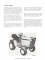
To The Owner
Assembled in this manual are operation, lubrica-
tion, and maintenance instructions for the Cub
Cadet 682 and 782 Tractors. The material has been
prepared in detail to help you better understand
the correct care and efficient operation of your
tractor. Before you operate the tractor, study this
manual carefully. Additional copies may be
ordered from your dealer at a nominal price.
Your local authorized Cub Cadet dealer is in-
terested in the performance you receive from this
tractor. He has factory-trained servicemen, in-
formed in the latest method of servicing tractors,
modern tools, and original-equipment service
parts which assure proper fit and good perform-
ance.
The Cub Cadet 682 and 782 Tractors have a
hydrostatic drive. It is the best hydrostatic drive
unit available and will require minimum service if
recommended operation and maintenance pro-
cedures are followed.
Eo
To obtain top performance and assure economical
operation, the tractor should be inspected,
depending on its use, periodically, or at least once
a year, by your authorized Cub Cadet dealer.
When in need of parts, always specify the model,
chassis, and engine serial numbers including the
prefix and suffix letters. Write these serial
numbers in the space provided on page 3.
Should you have difficulties with the unit consult
your International Harvester dealer. UNDER NO
CIRCUMSTANCES SHOULD YOU ATTEMPT TO
SERVICE THESE UNITS YOURSELF. Only your
dealer is authorized to repair or replace units on
this drive under the terms of the warranty. Should
you desire additional information not found in this
manual, contact your authorized Cub Cadet
dealer.
MA-17394
International Cub Cadet 682 Tractor Shown.
1
TO THE OWNER
SERIAL NUMBERS
INTRODUCTION a
SAFE OPERATING PRACTICES
ENERGY CONSERVATION
FOLLOW THESE
RECOMMENDATIONS
INSTRUMENTS AND CONTROLS -
BEFORE OPERATING YOUR '
TRACTOR
OPERATING THE TRACTOR
Governor
‘Throttle Lever | |
Speed Control Lever
Speed Control Lever Stop
Tractor Break-In Procedure
Starting the Engine
Stopping the Engine
Cold Weather Starting
Operating in Cold Weather
Hood and Noise Isolation Panels
Adjusting the Seat
Brake Pedal
Locking the Brake
Driving the Tractor
Seat Safety Switch
Driving on Slopes
Stopping the Tractor
ENGINE AND FUEL SYSTEM
Engine Oil
Fuel Shut-Off Valve
Hydrostatic Drive
Hydraulic Fluid Filter
Carburetor Adjustments
ENGINE COOLING AND
AIR CLEANER
Engine Cooling
Dry Type Air Cleaner with
Foam Pre-Cleaner Element
ELECTRICAL SYSTEM
Safety Starting Switch
Charge Indicator
Hour Meter
CONTENTS
4,5
7 to 11
со со со Со 00 UN
12 to 15
14
14
14, 15
15
16, 17
16
16, 17
17 to 21
7
17
17
Combination Lights and
Ignition Switch
Spark Plugs
Fuses
Battery
EQUIPMENT LIFT HANDLE
Height Adjustment (682 Tractor)
HYDRAULIC LIFT
(782 Tractor Only)
Operating Instructions
HITCHING EQUIPMENT
TO THE TRACTOR a
Drawbar ~~ =
Three-Point Hitch (Optional)
"FRONT POWER TAKE-OFF
Operating the Front
Power Take-Off Clutch
Adjusting the Power Take-Off Clutch
BRAKES
FRONT WHEELS
Front Wheel Toe-In
Turning Radius
PNEUMATIC TIRES
Inflation
Operating Pressure for Tires
Care of Tires
Rear Wheel Weights (Optional)
Mounting Tires on the Rim -
Tire Chains (Optional)
Overloading
SEAT MAINTENANCE
STORING THE TRACTOR
“Removing from Storage
“OPTIONAL EQUIPMENT
AND ACCESSORIES
MAINTENANCE CHART
TROUBLE SHOOTING
LUBRICATION TABLE
LUBRICATION GUIDE
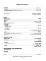
SPECIFICATIONS
METRIC (SI) MEASUREMENTS
CAUTION
TO PURCHASERS
OF INTERNAL COMBUSTION ENGINE EQUIPPED |
MACHINERY OR DEVICES IN THE STATE OF CALIFORNIA
17, 18
18
18
18, 19
19,20
19,20
20, 21
20, 21
25
26
27,28
28
29 to 31
32, 33
33
The equipment which you have just purchased does not have : a spark arrester. If this equipment is used on
any forest covered land, brush covered land, or grass covered unimproved land in the State of California,
before using on such land, the California law requires that a spark arrester be provided. In addition, the
spark arrester is required by law to be in effective working order. The spark arrester must be attached to
the exhaust system and comply. with Section 4442 of the California Public Resources Code.
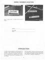
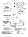
SERIAL NUMBER LOCATION
Cub
BROWNSVILLE TENN. 38012
MODEL
Serial number plate is located near left rear
fender.
MODEL
DELIVERY
DATE
A variety of extra equipment and accessories is LEFT and RIGHT indicate the left and right sides
available. Where operating and maintaining in- of the tractor when facing forward in the driver's
struction is required, it is included in the instruc- seat. Reference to FRONT indicates the grille end
tion for operating and maintaining the tractor. of the tractor; to REAR the drawbar end.
Disregard the instructions for equipment not on
your tractor.
Aue ail al ale
~~
р ЩИ -
4, WARNING $
To reduce the potential for any injury, comply with the following safety instructions. Failure to comply
with the instructions may result in personal injury.
SAFE OPERATION PRACTICES FOR RIDING VEHICLES
1.
“It is suggested that this manual be read in its
entirety before attempting to assemble or
operate this unit. Keep this manual in a safe
place for future reference and for ordering
replacement parts.
This unit is a precision piece of power equip-
ment, not a plaything. Therefore exercise ex-
treme caution at all times.
. Know the controls and how to stop quickly—
- READ THIS OWNER'S MANUAL. -— ...
. Dô not'allow children to operate vehicle. Do
not allow adults to operate it without proper
instruction. Only persons well. ‘acquainted
‘with these rules of safe operation should be
allowed to use your mower.
No one should operate this unit while intox-
icated or while taking medication that impairs
the senses or reactions.
Wear sturdy, rough-soled work shoes and
close- fitting slacks and shirts to avoid en-
tangiement in the moving parts. Never operate
a tractor in bare feet, sandals, or sneakers.
To prevent injury, do not carry passengers or
give rides. (Keep children, pets and by-
standers out of the area while mowing.) Only
the operator should ride on the unit and only
in the seat.
Check overhead clearance carefully before
driving under power lines, guy wires, bridges,
low hanging tree branches, before entering or
leaving buildings, or in other situations where
the operator may be struck or pulled from the
tractor which could result in serious injury.
To maintain control of the tractor and reduce
the possibility of upset or collision operate
the tractor smoothly—avoid erratic operation
- and excessive speed.
10.
11.
12.
13.
14,
15.
Keep the area of operation clear of all per-
sons, particularly small children and pets.
Stop engine when they are in the vicinity of
your mower. Although the area of operation
should be completely cleared of foreign ob-
jects, a small object may have been over-
16.
17.
Disengage power 10 attachment(s) and stop
engine before making any repairs or ad-
justments. Disconnect the spark plug wire
“and keep the wire away from the plug to pre-
vent accidental starting.
Before attempting to unclog the mower or
discharge chute, stop the engine. The mower
— blade(s) may continue to rotate for a few
18.
19.
20.
21.
22.
23.
24.
25.
looked and could be accidently thrown by the
mower in any direction and cause injury.
Clear work area of objects which might be
picked up and thrown by the mower in any
direction and cause Injury.
Stop the blade(s) when crossing gravel drives,
walks or roads.
Disengage all attachment clutches and shift.
into neutral before attempting to start engine.
Disengage. power to attachment(s) and stop
engine before leaving operating position.
Do not put hands or feet near or under rotating
parts. Keep clear of the discharge opening at
all times as the rotating blade(s) can cause in-
jury.
26.
27.
seconds after the engine is shut off.
Therefore, be sure the blade(s) have stopped
completely. Disconnect the spark plug wire
and keep the wire away from the plug to pre-
vent accidental starting.
Disengage power to attachment(s) when
transporting or not in use.
Take all possible precautions when leaving
vehicle unattended such as disengaging
power-take-off, lowering attachments, shift-
ing into neutral, setting parking brake, stop-
ping engine and removing key.
Do not stop or start suddenly when going
uphill or downhill, Mow up and down face of
steep slopes; never across the face.
Reduce speed on slopes and in sharp turns to
prevent tipping or loss of control. Always
keep the tractor in gear when going down
steep hills to take advantage of engine brak-
ing action.
Stay alert for hotes | in terrain and other hidden
hazards.
Use care when pulling loads or using heavy
equipment.
A. Use only approved drawbar hitch points.
~ B. Limitloads to those you can safely control.
C. Do not turn sharply. Use care when back-
ing.
D. Use counterweight(s) or wheel weights
when suggested in owner’s manual.
Watch out for traffic when crossing or near
roadways.
When using any attachments, never direct dis-
charge of material toward bystanders nor
allow anyone near vehicle while in operation.
Handle gasoline with care. It is highly flam-
mable.
A.. Use approved gasoline container.
B. Never remove cap or add gasoline to a run-
ning or hot engine or fill fuel tank indoors.
Wipe up spilled gasoline.
C. Open doors if engine is run in garage. Ex-
-— haust fumes are dangerous.. Do not run
engine indoors.
Keep the vehicle and attachments in good
operating condition, and keep safety devices
in place. Use guards as instructed in
operator’ 5 manual. |
28.
29.
30.
31.
32.
33.
Keep all nuts, bolts, and screws tight to be =
sure the equipment is in safe working condi-
09) Shut the engine off and wait until the
“blade comes to a complete stop before
tion. removing the grass catcher.
Never store the equipment with gasoline in (4) Check blade mounting bolts for proper
the tank inside a building where fumes may | tightness at frequent intervals.
reach an open flame or spark. Allow engine to 34. Check grass catcher bags frequently for wear
cool before storing in any enclosure.
or deterioration. For safety protection, replace
To reduce fire hazard, keep engine free of only with new bag meeting original equipment
grass, leaves or excessive grease. - specifications.
The vehicle and attachments should be 35. Look behind to make sure the area is clear
stopped and inspected for damage after strik-
ing a foreign object. The damage should be
before placing the transmission in reverse
and continue looking behind while backing
repaired before restarting and operating the — UP.
equipment. . 36. Whenever possible, avoid driving the tractor
Do not change the engine governor settings
on an incline such as a ramp or slope. If
or overspeed the engine. necessary to move the tractor on an incline,
When using the vehicle with mower, proceed
as follows:
(1) Mow only in daylight or in good artificial
whenever practical back the tractor up the in-
cline and drive the tractor forward down the
incline. Use extreme caution if it is necessary
light. to drive the tractor up an incline or back the
(2) Never make a cutting height adjustment tractor down an incline because the front of
while engine is running if operator must the tractor could lift and rapidly flip over
dismount to do so. backward which could cause serious injury.
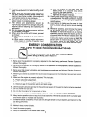
ENERGY CONSERVATION
FOLLOW THESE RECOMMENDATIONS
An Energy Conservation Plan is your best insurance against
waste. Energy is Money. Don’t Waste It!! |
An Energy Conservation Plan consists of:
1.
O ONO
11.
12.
- 13.
14.
15.
Being sure the equipment is properly adjusted to the task being performed. Review Operator's
Manual thoroughiy.
Being sure the operator is thoroughly trained in the operation of the equipment. Review Operators
Manual thoroughly. .
. Being sure that proper lubrication and maintenance procedures : are followed. Review Operators
Manual thoroughly.
Matching as closely as possible the tractor size (horsepower) to the implement size and soil condi-
tions.
. Make sure the engine is properly adjusted. This includes:
A. Proper carburetor adjustment.
B. Fuel and air filter servicing at the proper intervals.
C. Check air gap of the ignition points and spark plugs. |
Use the proper lubricants and fuel for the particular season of the year the tractor is being operated.
Do not overfill the fuel tank.
Do not idle the engine for long periods of time.
. Make sure the tires are inflated properly. Refer to “Tires” for various inflation pressures.
10.
Many tractor operations do not require full load operation. Whenever possible shift to a higher gear
and throttle back to increase fuel economy.
Excessive ballast is wasteful of fuel. Use only enough ballast to insure stability and traction for the
job being performed.
Make the minimum number of passes over the field.
Maintain sharp mower blades.
Level the mower properly.
Keep the underside of the mower deck clean.
MA-17477
>
me E N
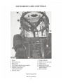
INSTRUMENTS AND CONTROLS
Fuses
Choke control
Brake pedal lock
Brake pedal
Front power take-off control switch
Hydraulic lift control lever
Hydraulic front power
outlet control lever®
steering wheel
‘Optional Equipment
782 Tractor Shown
6
EEE ml соа
. Charge indicator
. Hour meter
. Speed control lever stop
. Thrattie lever
. apeed control lever
. Combination lights and
ignition switch
. Cam lock knob
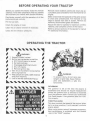
BEFORE OPERATING YOUR TRACTOP
Before you operate the tractor study this manual
carefully. It has been prepared to help you operate
and maintain your tractor with utmost efficiency.
Familiarize yourself with the operation of all the
instruments and controls.
Fill the fuel tank.
Check the engine oil level.
Clean the air cleaner element if necessary.
Check the tire inflation pressures.
Remove noise isolation panels and clean any ac-
cumulated grass and debris from the intake fan on
engine.
Make certain that the backside of the grille screen
is clean and unobstructed. Pull forward on top
edge to expose rear side of screen. Remove by
hand any accumulated grass and debris.
Adjust the seat for operators maximum comfort,
visibility, and complete control of the tractor.
Refer to various sections of the operators manual
far additional information.
OPERATING THE TRACTOR
<<< <<< че
/N\ warning
# 1. Keep all shields in place.
2. Before leaving operator's position:
# a. Shift transmission to neutral
b. Set parking brake
# c. Disengage attachment clutch
d. Shut off engine
# e. Remove ignition key
3. Wait for all movement to stop before
# servicing machine.
4. Keep people and pets a safe distance
# away from machine.
>. Look to the rear before backing up.
1 A
DO NOT OPERATEF,
MOWER UNLESS)
y
; GUARD OR ENTIRE Я
/
A
GRASS CATCHER IS
IN ITS PROPER PLACE. La
RR. М
e QUO
ь-< << <<< ``
MAAS TE
To prevent injury, do not carry pas-
sengers Or give rides. Keep children,
pets and bystanders a safe dis-
tance away.
GOVERNOR
The governor is set at the time the engine is
assembled and should not require readjustment
unless the governor arm is removed or loosened
from the governor shaft. Consult your authorized
Cub Cadet dealer if the governor does not func-
tion properly.
THROTTLE LEVER
This lever controls the speed of the engine. When
set in a given position, it will maintain a uniform
engine speed.
When using power take-off operated equipment,
best performance is achieved with the throttle
ever in the “FAST” position.
y This symbol shows fast position.
«В This symbol shows slow position.
SPEED CONTROL LEVER
The lever is used to select any speed from a stand-
still “N” position to eight miles per hour in the for-
ward direction and to four miles per hour in the
reverse direction. |
Moving the speed control lever forward provides
increased forward speed, and moving the lever
rearward provides the reverse speeds. Refer to
“Instruments and Controls.”
NOTE:
Do not rest your foot on the brake
pedal while driving the tractor as
this would cause the speed control
lever to return to the “N” position.
SPEED CONTROL LEVER STOP |
An adjustable speed control lever stop is provided
to allow the operator to return to a predetermined
speed.
TRACTOR BREAK- IN PROCEDURE
Never. operate a new engine immediately under
full load. Break it in carefully as shown in the table
below.
Engine Throttle
Control Lever
Period Position Load
v2 | 34а |Full |
1st hour XxX | |None
X_|-— fight drawbar foad _ _
2nd hour 1 PET X "Mowing with tractor at
| | slow speed |
ZZ XI [Medium drawbar Toad |
3rd through bk Jdo o bs ——— ——
- 13th hour ‚X "Normal mowing
STARTING THE ENGINE
1. Be sure there is an adequate supply of fuel in
the tank.
A WARNING
To avoid fire or injury, tighten fuel
cap securely. Never remove the
fuel tank cap or fill the fuel tank
when the engine is running, or
hot; or in—doors. Also, do not
smoke when working around flam-
mable fuel.
2. Be sure the fuel shut-off valve is open.
3. Pull choke control button to full choke posi-
tion. Less choking may be necessary due to
~ variations in temperature, grade of fuel, etc.
~ Little or no choking will be needed when the
engine is warm.
4. Place the throttle on the “FAST” position
5. To start the engine, safety starting switches
must be activated by pressing the brake pedal
all the way down and moving the power take-
off clutch switch to the disengaged position.
NOTE:
The speed control lever will re-
turn to neutral when the brake
pedal is pressed all the way
down. |
6. Turn the ignition key clockwise to the
— “START” position and release it as soon as
the engine starts; however do not operate the
starter for more than 30 seconds at any one
time. If the engine does not start within this.
time, turn the key “OFF” and wait a few
minutes, then try again.
7. After the engine starts, slowly release the
brake pedal and gradually push the choke con-
trol button all the way in. Do not use the choke
to enrich the fuel mixture, except as.
necessary to start the engine.
IMPORTANT:
If you strike a foreign object, stop
the engine. Remove wire from
spark plug, thoroughly inspect
the mower for any damage, and
repair the damage before restart-
ing and operating the mower.
STOPPING THE ENGINE
Move the throttle lever to the “SLOW” position
and allow the engine to idle for a short time before
stopping. Then turn the key to the “OFF” position.
COLD WEATHER STARTING
To start engine in cola weather use correct weight
of gngine oil, be sure battery is fully charged, and
the proper starting. procedure is. followed. The
best procedure for‘ starting at temperatures near
or below freezing is as’ follows:
1. Pull the choke all ‘the way out into the full
choke position.
2. Place the 1nrottle lever just off “FAST” posi-
tion. |
3. Press the brake pedal all the way down and be
sure the power take-off switch is in the off
positon. The safety interlocks will prevent
starting unless this is done.
4. Move the key switch into the start position
and hold until the engine starts; however, do
not operate the starter for more than 30
seconds at any one time. As soon as the
engine starts, slowly push the choke in part
way.
À WARNING
During operation do not run the
engine in confined area such as
storage building any longer than is
necessary. Immediately move the
tractor outside into the air.
NOTE:
In cold weather the starting motor
may disengage prematurely. This is
caused by the engine firing once but
failing to continue running. If this
happens several times, the engine
will be flooded and it will be
necessary to leave the throttle in the
fast position but push the choke in
all the way; then turn the ignition
Key to the start position and slowly
pull the choke out to the position
which will cause the engine to start
and continue running. If the engine
falters after putting tractor into
motion, pull the choke out part way
until the engine runs smoothly, then
gradually push the choke back in as
the engine warms.
OPERATING IN COLD WEATHER
While operating this tractor equipped witha 17 HP
2 cylinder engine, at light loads and usually in low
temperature conditions, itis possible to foul out a
spark plug. This will result in gasoline entering the
crankcase by way of the piston rings on the
cylinder which is not firing.
Some symptoms are:
1. Oil level will rise due to gasoline in crankcase.
2. Air filter becomes oil and fuel soaked.
3. Engine leaks oil.
4. Mis-firing.
This condition does not necessarily mean that the
carburetor, piston rings, ignition coil-wires-points,
or gaskets are defective.
Correction:
1. Replace both spark plugs.
Check air filter element, replace if needed.
Change oil.
Adjust carburetor if needed.
от о во В
Service spark plugs regularly when using trac-
tor under light duty or low temperature condi-
tions.
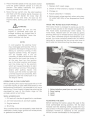
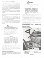
HOOD AND NOISE ISOLATION PANELS
The tractor hood is arranged to swing up and for-
ward for easy access to the engine compartment.
The hood locks automatically when raised. To
lower hood, release latch on left side by gently
pushing hood up to release tension and pull latch
to left. Also, whenever engine maintenance is re-
quired, the noise isolation panels can be readily
removed by removing the two wing nuts (one on
each side) and disconnecting the panel spring.
A em
a.
E MA-185590
Noise isolation panel (one on each side)
Panel spring
Latch
Hood
> WN
ADJUSTING THE SEAT
Before starting the tractor, adjust the seat to the
most comfortable driving position. Tilt the seat
forward over the steering wheel, loosen the four
cap screws in the seat support, and slide the seat
assembly forward or rearward to the position
which is most comfortable for the operator.
Retighten the cap screws after the seat is ad-
justed.
NOTE:
The battery is located in a well under
the operator's seat for ease in ser-
vicing or replacement when neces-
sary.
BRAKE PEDAL
Brake pedal must be pressed all the way down to
activate the safety starting switch. When brake
pedal is in the depressed position it automatically
moves the speed control lever to the “N”' position.
The tractor can be stopped either by pressing the
pedal all the way down, or placing the speed con-
trol lever in the “N” position.
LOCKING THE BRAKE
Always lock the brake when the tractor is parked
on a grade. To lock the brake, press down on the
pedal; then place the brake pedal lock in the
engaged position. To disengage the lock, press
down on the pedal, lift the lock up and place it in
the disengaged position.
CE
BA
1. Brake pedal
2. Brake pedal lock
Brake pedal lock in the engaged position.
10
À WARNING
The hydrostatic transmission will
not hold the tractor on a hill. In a
short period of time (depending on
the hill) the oil will drain from the
transmission and allow the tractor
to roll down hill. To avoid an acci-
dent and/or possible injury, lock the
brake.
DRIVING THE TRACTOR
1. Depress the standard brake pedal, release the
brake lock, and let the pedal up. Move the
throttle lever to the position where the engine
operates best for the load to be handled.
2. Start the tractor in motion by moving the
speed control lever slowly forward or rearward
as described above.
WARNING
Avoid sudden starts, excessive
speed, sudden stops. Keep vehicle
in gear when going down hills.
NOTE:
When using power take-off operated
equipment best performance is
achieved with the throttle lever in
the “FAST” position,
SEAT SAFETY SWITCH
When using power take-off operated equipment,
the operator must remain in tractor seat at all
times. If operator should leave tractor seat
without turning off the power take-off switch, the
engine will automatically shut off.
DRIVING ÓN SLOPES
Before operating the tractor on any slope, walk the
slope to look for possible hazards such as rocks,
mounds, ruts, stumps or other surface ir-
regularities which could cause an upset.
Back the tractor with implement up the steepest |
portion of each slope you intend to work. If the
tractor can not negotiate the slope in reverse, the
‘slope is too steep to be worked.
| WARNING
Always drive up or down the face of
a slope. Do not drive so that the
tractor may tip over sideways.
Avoid turns when driving on a slope. If a turn must
be made, turn down the slope. Turning up a slope
greatly increases the chance of a roll over.
Avoid stopping when driving up a slope. If it is
necessary to stop while driving up a slope, start
up smoothly and carefully to reduce the possibili-
ty of flipping the tractor over backward.
STOPPING THE TRACTOR
Move the speed control lever to the “N” position
_ Or use the standard brake pedal. Before dismount-
ing always lock the brake pedal and turn the igni-
tion “OFF.” Also disengage the power take-off
control switch. | |
11
Always engage park, lower equip-
ment and shut off engine before dis-
mounting. Never start engine from
ground.
ENGINE AND FUEL SYSTEM
wma
NEVER SMOKE while refueling.
Shut off engine and electrical equip-
ment.
This engine is designed to operate on unleaded or
leaded gasoline with a 91 minimum octane rating
(Research Method), or a minimum Antiknock In-
dex (RON + MON)? or 87. Antiknock Index is
posted on dispensing pumps.
The use of unleaded gasoline will increase spark
plug and valve life, maintain engine performance
Pb
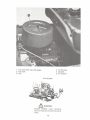
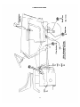
1. Fuel tank filler cap and gauge
2. Fuel tank
3. Coil
E o ARTE a tee A ee й к
este Pr A ETA A RE) LO TA
Le fe + EE ut - LALA
ой Les dr CPE Tee, cl a A Sy Le, A
a eT Ry lor pall BS re = Re
e. Aa e
TER UT a AN A a Re г E
longer, and reduce rust and corrosion of the
engine while stored.
The fuel tank filler cap has an air vent. Keep the
vent open at all times to assure proper flow of the
fuel.
NOTE:
Gasohol is not approved for use by
the engine manufacturer and should
not be used. The use of gasohol may
damage the engine.
E
e E E fa
ис
с
a
E E
ie A
pe As Era
en
hg ee e ET
7389
4. Qil fill plug
5. Dipstick
6. Air cleaner
Fuel System
%
са em
RRR.
e |
|
|
|
Г.
Je
ery
—. MA:
1. Fuel tank filler cap and gauge 4. Oil fill plug
2. Fuel tank 5. Dipstick
3. Coil 6. Air cleaner
Fuel System
NEVER SMOKE while refueling.
Shut off engine and electrical equip-
ment.
13
Use clean fuel and keep it clean. Store fuel in
tanks equipped with hose and nozzle to prevent
contamination of the fuel. The use of funnels,
cans and drums is not recommended because
they are difficult to keep clean.
Allow space for expansion when adding fuel to
the tank. A tank filled to capacity may overflow if
exposed to a rise in temperature or direct
sunlight.
Before starting the engine, check the fuel tank cap
to be certain it is tightened completely.
ENGINE OIL
The engine crankcase is filled with break-in oil.
This oil may be used for the first 5 hours of engine
operation at temperatures between + 90°F. and
0°F. (32°C. and —22°C.). If temperatures are not
within this range, drain the oil from the crankcase
and replace with new oil as specified in the
“LUBRICATION TABLE.” The engine oil must be
drained and replaced with new oil every 30 hours
of engine operation.
To aid starting, the selection of crankcase
lubricating oils should be based on the lowest an-
ticipated temperatures until the next drain period.
Refer to “LUBRICATION TABLE.”
We recommend IH Low Ash Engine Oil for
gasoline engines. IH Low Ash Engine Oil exceeds
API Service Classification SE. It is specifically
designed for heavy duty service in gasoline
engines, and is formulated to minimize metallic
deposits, lengthen spark plug and valve life. IH
Low Ash Oil used with unleaded gasoline is the
ideal combination to maintain performance and
extend engine life.
If other than IH Low Ash Engine Oil is used it must
meet API Service Classification SE. For maximum
engine life select API SE olls with lowest levels of
barium, calcium, or magnesium additives and
minimum ash content (approximately 0.5%).
Lubricant suppliers will normally furnish this in-
formation on their engine oils.
Multi-viscosity numbered oils such as SAE
10W-30 or SAE 10W-40 must not be used above 32
degrees Fahrenheit (0 degrees Celsius).
Regularly check the oil level of the engine
crankcase to see that it is filled to the correct
level.
NOTE:
Check the oil level only while the
engine is stopped.
Always keep the oil level between the “FULL” and
the “LOW” marks on the dipstick. When checking
14
the oil level the dipstick must be withdrawn and
wiped clean, then inserted all the way and
withdrawn for a true reading.
Filling the Crankcase
To fill the crankcase with oil, place the tractorona
level surface. Clean the area around oil fill plug
before removing.
Remove oil filler plug and fill crankcase to the full
mark on dipstick, (capacity 3 pints, 1.4 L). Check
oil level on dipstick before adding more oil. Wipe
off dipstick before inserting it all the way into the
tube, then remove dipstick and check oil level. DO
NOT OVERFILL. Dipstick must be pushed fully in-
to tube at all times when engine is operating.
NOTE:
Never overfill the engine crankcase.
Engine may overheat and/or damage
may result if the crankcase is over
the “FULL” mark (or below the
“LOW” mark). For oil capacity
refer to the “SPECIFICATION”
and “LUBRICATION TABLE" sec-
tion.
FUEL SHUT-OFF VALVE
Be sure the shut-off valve under the fuel tank is
open.
To turn the fuel on,
clockwise to the stop.
To turn the fuel off, turn the knob clockwise until
it is tight.
turn the knob counter-
1. Fuel shut-off valve.
2. Fuel filter (not seen)
HYDROSTATIC DRIVE HYDRAULIC FLUID
FILTER
Remove the throw-away can-type filter and replace
with a new filter after the first 10 hours and 50
hours of operation, and every 100 hours of opera-
tion thereafter.
NOTE:
Clean the outside area before re-
moving the filter to keep dirt from
getting into the transmission case.
If a mower is mounted on the tractor,
the mower must be lowered to facili-
tate removal of the filter.
To remove the filter, turn the filter counter-
clockwise using an automotive type filter wrench.
Before installing the new filter, apply a coating of
oil on the filter gasket. Thread the filter on by hand
until tight enough to seat the gasket. Loosen the
filter. Then turn it until the gasket contacts the
base. Tighten the filter an additional one half turn.
Start engine and allow it to run for a few minutes.
Shut engine off and check for leaks, check oil
level in transmission case. I
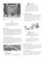
CARBURETOR ADJUSTMENTS |
A WARNING
To avoid injury or an accident, be
sure the brake pedal is in the locked
position, transmission is in neutral,
and any equipment is disengaged
before starting engine to make car-
buretor adjustments. Keep clear of
all moving parts. Be careful of
heated surfaces and muffler.
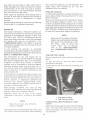
MA-17387
1. Main fuel screw
2. Idle fuel screw
3. Idie speed screw
The carburetor is adjusted at the factory and
under normal operating conditions it will not re-
quire readjusting. If the engine does not operate
properly what may appear to be a faulty carburetor
adjustment is in many cases a clogged air filter.
— This possibility should be ruled out before
attempting to readjust carburetor. Refer to
“ENGINE COOLING AND AIR CLEANER” (page
16). | | |
If readjustment becomes necessary, stop the
engine, then turn the MAIN and IDLE fuel ad-
justing screws all the way in, until they bottom
lightly.
NOTE:
To prevent possible damage to the
carburetor needles, be very careful
closing the carburetor needles be-
fore basic adjustments are made.
Improper adjustment of the carbu-
retor may result in engine damage.
Main Fuel Adjustment | 1
Preliminary setting—turn screw out 2% turns.
Final setting—start engine and raise engine
speed to maximum governed, no load speed. Turn
screw in just until engine speed decreases and
note the position of the screw. Now turn the screw
out. The engine speed will first increase, but then
decrease as screw is turned out. Note the position
of screw when engine speed starts to decrease.
Set the screw midway between the two points
noted above.
Idle Speed Adjustment
‘Run engine at maximum governed, no load speed
for a minimum of 30 seconds, then allow engine
Speed to fall to idle or put throttle into idle posi-
tion. Set engine speed to 1200 ( + 75 RPM) by turn-
ing the idle speed screw in or out.
Idle Fuel Adjustment
Set the idle fuel mixture by turning the idle fuel
screw out, from the closed position, % to 1 full
— turn.
15
(À warnine
Exhaust fumes can kill. Never run.
engine inside buildings.
ENGINE COOLING AND AIR CLEANER
ENGINE COOLING
This tractor has an air cooled engine. Air must be
able to circulate freely around the engine, through
the screen, shroud, and over the fins of the cylin- _
der block. Keep these areas free of accumulated
dirt and trash or engine will overheat and result in
damaged moving parts. Periodically clean the in-
side of the side panels and grille screen for ade-
quate cooling.
NOTE:
This machine is designed to cool
properly with the engine side panels
in place. Operating the machine
“without panels in place may result
in inadequate cooling. Never oper-
ate engine with blower housing or
cooling shrouds removed. These
direct air flow past cooling fins. Re-
moval results in improper air circu-
lation, overheating and engine dam-
age.
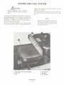
DRY TYPE AIR CLEANER WITH FOAM PRE-
CLEANER ELEMENT
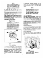
MA-17386 A
1. Wing nuts 6. Foam pre-cleaner
2. Cover element
3. Seal — 7. Base back
4. Cover plate — plate
5. Paper cartridge 8. Tube
Air cleaner assembly
dd MA-18933
1. Wing nut 5. Paper cartridge
2. Cover 6. Foam pre-cleaner
3. Rubber tube element
4. Cover plate 7. Base back plate
Air cleaner assembly
Servicing Foam Pre-cleaner Element
Clean and re-oil foam pre-cleaner element at 1
month intervals or every 10 hours, whichever oc-
curs first.
— NOTE:
Service more often under dusty
conditions.
1. Remove wing nut(s) and cover. |
2. Remove foam pre-cleaner element by sliding
it up off of the paper cartridge.
3. A. Wash pre-cleaner element in liquid deter-
~~ gentand water.
° B. Squeeze dry in cloth.
C. Saturate in engine oil. Squeeze to distrib-
| ute evenly.
D. Wrap in shop towel and squeeze tor remove
excess oil.
Discard used element and replace with new one at
least once a year.
16
Servicing Paper Cartridge
This engine is equipped with a dry type air cleaner
element, which should be checked every 100 oper-
ating hours and replaced if dirty. It should be
checked and if necessary replaced more often
under extremely dirty dusty conditions. Do not
wash element in any liquid or attempt to blow dirt
off with air hose as this will puncture filter ele-
ment. Carefully handle new element—do not use
if gasket surfaces are bent or twisted. Check the
following when installing a new element.
1. Back plate must be flat on gasket of carburet-
or elbow. Replace back plate if bent or
cracked.
2. Gasket surfaces of element must be flat
against back plate and cover to seal effective-
ly.
3. Seal on cover must be in place to reduce
noise and vibration of the cover. Vibration can
cause stud hole in cover to enlarge, thus рег-
mitting dirt to enter carburetor.
4. Wing nuts must be finger tight—do not over-
tighten.
Properly cleaned and installed air cleaner
elements are the best guarantee to continued
long and satisfactory engine life.
ELECTRICAL SYSTEM
The twelve-volt electrical system consists princi-
pally of a rectifier, alternator, starting motor, and a
twelve-volt battery, ignition coil, condenser,
breaker points and spark plugs.
All connections must be clean and securely fas-
tened.
SAFETY STARTING SWITCH
The safety starting switches activated by the
brake pedal and the power take-off clutch switch
serve to prevent starting the engine accidentally.
The brake pedal must be depressed and the power
take-off switch in “OFF” postion before engine
will start.
(ÁN warning
Do not operate the tractor if the
interlock system is malfunctioning
because it is a safety device, de-
signed for protection.
CHARGE INDICATOR
This instrument indicates whether the alternator
Is charging or the battery is discharging. If it
shows discharge continuously, investigate the
cause to avoid completely discharging the battery
and possible damage to the charging circuit.
17
HOUR METER
The hour meter is located on the instrument pan-
el. It indicates the actual hours of engine opera-
tion, enabling the operator to determine without
guesswork, when lubrication, change of oil or
periodic inspections are necessary. It also pro-
vides a means of computing cost of specific jobs.
The hour meter operates whenever the engine is
running or the ignition key is in the “ON" position.
When the red hand is located on the red areas of
the hour meter dial (every 10 hours), this indicates
a service period is necessary. Refer to “Mainte-
nance Chart” and “Lubrication Guide” for 10 and
30 hour service requirements.
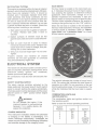
| МА-16231 |
The red dial indicates the number of hours from 0
to 60. The yellow dial indicates the total hours of
operation up to 600. For one revolution of the red
dial the yellow dial moves 1/10 of a revolution. The
white dial indicates that the hour meter is operat-
ing.
COMBINATION LIGHTS AND
IGNITION SWITCH
The combination lights and ignition switch is a
four position switch.
Refer to chart for various operating positions.
Switch
Position Lights Ignition
1 Off Off
2 On On
3 Off On
4 Off Actuates
starting
motor
NOTE:
When the engine is not operating,
the key must be turned to the OFF”
position to prevent battery dis-
charge.
The headlights are sealed-beam units. Refer to
“SPECIFICATIONS” when replacement is neces-
sary.
To replace the taillight lamp, remove socket and
bulb from the back of the taillight by rotating sock-
et 14 turn. Refer to “SPECIFICATIONS.”
SPARK PLUGS
А-69529 А
Checking the spark plug gap.
Set gap at .025-inch (.64 mm).
NOTE:
Remove all dirt from around the
spark plugs before removing.
To remove spark plugs, always use a spark plug
wrench. Check gap after every 100 hours of opera-
tion,
ZA wannina
To avoid possible injury, be sure
engine is off and cool before mak-
ing any adjustments or repairs.
Replace a defective plug with a new plug, tighten
plug to 10-15 ft.-Ibs. (13.5-20.3 N-m). See your
authorized Cub Cadet dealer for the correct re-
placement plug.
18
Cleaning Spark Plug
Clean spark plugs with a pen knife or wire brush
and solvent. If electrode is burned away or the
porcelain is cracked, replace with new plug.
NOTE:
Do not sandblast or use any abra-
sive machines to clean spark plugs;
because any grit introduced into the
engine could cause severe damage.
FUSES (Electric Lighting and Electric Power Take-
Off Clutch)
There are two fuses on the tractor pedestal. The
fuse on the left is for the lights; the fuse on the
right is for the electric clutch.
Always use the same capacity fuse for replace-
ment. Refer to “SPECIFICATIONS.” If the lights
fail or the electric clutch does not engage, check
the appropriate fuse.
To install a new fuse, press in on the fuse housing
cap and turn counterclockwise to remove it from
the fuse housing. Remove the old fuse and re-
place it with a new one. Then reassemble the cap
to the housing.
BATTERY
Cigarettes. Hames. or sparks could cause:
battery 10 explode’ Always shield eyes and...
NGER face from battery Do not charge or use!
booster cables or adjust post connections
withaut proper instruction and traming
EXPLOSIVE GASES / POISON Contmins sulfuric acid Avoid contact |
CAUSES SEVERE BURNS: with skin, eyes or clothing In evemt of
sccident flush with water and call physician
KEEP OUT OF REACH OF CHILDREN immediately
MA-17150
Before working on any part of the electrical sys-
tem, disconnect the battery ground cable at the
battery negative (—) terminal. Do not reconnect
this cable until all work has been completed. This
will prevent shorting and damage to any of the
electrical units. Examine the electrical cables oc-
casionally to be sure they are not being frayed by
contact with adjacent parts.
When replacing a battery, make certain the ground
dable is connected to the negative (— ) terminal on
the battery. Be sure the rubber boot is properly
positioned over the positive (+) terminal on the
battery.
NOTE:
Both cables must be assembled
with the nuts to the inside of the ter-
minals to prevent shorting against
fender well.
Cleaning and Servicing the Battery
Occasionally remove the battery cables and
brighten the terminal contact surfaces with wire
wool, and reassemble them. Apply a light coat of
vaseline or chassis lubricant. Be sure the termi-
nals are clamped tightly and that the battery is
fastened securely in the battery box. Replace un-
serviceable cable. Keep the vent holes in the bat-
tery filler caps open.
Keeping the battery fully charged not only adds to
its life but makes it available for instant use when
needed.
Liquid Level
Check the battery at least once a month for elec-
trolyte level.
The electrolyte (acid and water) in each cell
should be at ring level at all times to prevent bat-
tery failure. When the electrolyte is below this
level, add pure, distilled water.
Acid or electrolyte should never be added except
by a skilled battery man. Under no circumstances
add any special battery “dopes', solutions or
powders.
A WARNING
If the tractor is to be tipped up or on
its side remove the battery to avoid
spilling the electrolyte. Battery elec-
trolyte is poisonous and can be in-
jurious to eyes, skin, and clothing.
If electrolyte is spilled, flush immed-
iately with water, followed by a so-
lution of one part baking soda to
four parts water.
NOTE:
Undercharging of the battery may
occur when using the tractor for
short periods of time (under V2 hour)
with a snow blower in very cold
weather. Under this condition run
the engine at high idle with the
power take-off clutch disengaged.
Overcharging may occur when using the tractor
for long periods of time (8 hours or more) without
the power take-off clutch engaged. Run the en-
gine with the power take-off clutch engaged, if
safely possible. Also, check the water level of the
battery and keep filled.
Connecting Booster Batteries
When required, a booster 12-volt battery may be
connected in parallel with the 12-volt system on
the tractor.
19
A WARNING
Gas discharged by battery is explo-
sive. Avoid sparks near the battery.
NOTE:
All circuits must be turned “off.”
Electrical system is NEGATIVE (—)
grounded only. Reversed polarity
will result in permanent damage to
components of the electrical sys-
tem.
The first jumper cable must connect the positive
(+) terminal of the booster battery and the
positive terminal of the battery on the tractor.
The second jumper cable must first be connected
to the negative (—) terminal of the booster battery;
and then to a point on the frame of the tractor,
away from the battery, having a good ground, so
no spark occurs near the battery.
For dependable battery service, see your autho-
rized Cub Cadet dealer.
EQUIPMENT LIFT HANDLE
682 TRACTOR ONLY
HEIGHT ADJUSTMENT
1. Release button
2. Handle grip
3. Lift handle
4. Lift pointer
5. Lift handle ratchet
682 Tractor
The lift handle is used to lift or lower equipment
used with the tractor. The equipment can be set in
multiple positions by depressing the button on
the top of the handle and releasing it when the
desired position is reached.
NOTE:
Refer to the equipment manual for
proper hitching instructions.
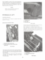
HYDRAULIC LIFT
782 TRACTOR ONLY
The hydraulic lift is ready to operate when the
engine is running.
OPERATING INSTRUCTIONS
1. Hydraulic lift control lever
2. Front hydraulic outlet control lever
(Optional)
782 Tractor
The hydraulic lift control lever is spring loaded. To
raise the equipment move the lever back, toward
the tractor seat. To lower the equipment move the
lever forward.
The front hydraulic outlet control lever (optional)
provides for “on-the-go” angling of a front
mounted blade.
|
№ ной Вы
j
a
E
TE pe я
EER
5 Lon CA
aa
E ro
pun
[a ;
i
1. Locking knob
2. Cam stop
3. Rockshaft arm
782 Tractor
The cam stop may be adjusted to allow the imple-
ment to return to a single preset height.
With implement in desired height position, re-
lease cam stop by turning locking knob counter-
clockwise. Turn cam stop until it contacts lift
bracket. Lock cam stop into this position by turn-
ing cam knob clockwise.
oa
Ba
. Lift bracket
2. Hold (not seen) for bolt
3. Lift arm
MA-17413B
782 Tractor
20
Equipment is normally operated in a “Float” posi-
tion (implement free to move upward).
To operate equipment in a fixed “Locked” posi-
tion, where down pressure of the implement is re-
quired (blade work), remove frame cover and in-
stall bolt, Y2 x 1-1/8-inch (12.7 x 28.55 mm), (not fur-
nished with tractor) between the lift arm and lift
bracket.
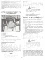
HITCHING EQUIPMENT TO
THE TRACTOR
Ss
МА-17633
1. Lift lever
2. Drawbar
3. Lower mounting bracket
Drawbar and three-point hitch.
DRAWBAR
Drawbar equipment must be hitched to the tractor
only at the hitch hole in the drawbar.
THREE-POINT HITCH (OPTIONAL)
682 Tractor
When the tractor has a three-point hitch, equip-
ment adaptable to this hitch is raised and lowered
with the lift handle. The lift handle can be set to
hold the equipment at various positions by use of
the notches in the lift handle ratchet. The lower
mounting bracket at the rear has three holes
which are used for additional adjustment. Refer to
“EQUIPMENT LIFT HANDLE.”
NOTE:
Refer to the equipment manual for
proper hitching instructions.
21
782 Tractor
When the tractor has a three-point hitzh, equip-
ment adaptable to this hitch is raised or lowered
with the hydraulic lift control lever. Refer to “Hy-
draulic Lift”.
/N warning
To prevent an accident disengage
power to any attachment when
transporting or not in use.
NOTE:
Refer to the equipment manual for
proper hitching instructions.
FRONT POWER TAKE-OFF
OPERATING THE FRONT POWER TAKE-OFF
CLUTCH
The front power take-off is an electric clutch
operated by a toggle switch on the left side of the
instrument panel.
1. Move the throttle lever back to the medium or
“slow” position.
2. Flip the toggle switch to the “ON” position.
3. Advance throttle to operating speed (full
speed).
4. The operator must remain in tractor seat at all
times. If operator should leave tractor seat
without turning off the power take-off switch,
the engine will automatically shut off.
ADJUSTING THE POWER TAKE-OFF
CLUTCH
The clutch is factory adjusted and should not re-
quire further adjustment under normal operating
conditions. However, if the clutch fails to operate
properly check as follows:
(À warning
To avoid possible injury, always dis-
engage all clutches, shift the trans-
mission into neutral, depress the
brake, set the brake pedal lock and
turn the ignition “OFF” before
working on the machine.
Check fuse on pedestal.
Using a feeler gauge, check the air gap. Insert the
feeler gauge into one of the three access slots
located around the outside of the brake plate. The
air gap should be .010-.015-inches (.254-.381 mm).
Adjust the self-locking nuts to obtain proper
clearance. Repeat adjustment at all three access
slots.
NOTE:
If brake plate drags on clutch at
.010-.015-inches (.254-,381 mm) air
gap, increase air gap to .020- inch
(.508 mm).
If the above procedure does not work, see your
authorized Cub Cadet dealer.
A WARNING
To avoid an accident or possible
injury, always disengage all
clutches, shift the transmission
into the neutral, depress the brake,
set the brake pedal lock and turn
the ignition “OFF” before working
on the machine.
MA-17344B
1. Access slots
2. Brake plate
3. Self-locking nuts
BRAKES
Speed control handle centering
zone when brake pedal is used
“№ position.
Transmission is in neutral
Braking zone.
Brake must
be engaging.
With pedal lock in position
as shown brakes must
withstand a torque of
100 ft. Ibs. (135 N-m) —
per wheel |
Wear zone Pedal stop -— |
MA.5151A =
Brake adjustments.
A WARNING | | Tianten jam nut “B” while holding the adjusting
To avoid injury or possible accident, If brake drags after tightening jam nut “B”, loosen
be very careful and take necessary the jam nut and back off adjusting screw “°С”
precautions when raising tractor off slightly and retighten jam nut “B.” Recheck brake
the ground. “adjustment and insure proper brake operation
. CL before operating tractor.
During normal operation of this machine, the |
brakes are subject to wear and will require A
periodic examination and adjustment. yan WARNING
To adjust the brake, loosen jam nut “B.” Next, Remember—A careful operator is
tighten the brake lever adjusting screw *“C” until the best insurance against an acci-
finger tight (8-10-inch pounds) (.904-1.130 N-m). dent.
22
Internal wet brakes.
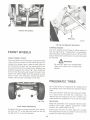
FRONT WHEELS
FRONT WHEEL TOE-IN
The front wheel toe-in dimension is approximately
1/8-inch (3.2 mm) closer in front than in the rear. To
measure for proper toe-in, make a chalk mark on
the centerline of each tire the same height from
the ground as the front wheel hubs. Measure the
distance between the marks “A”, then rotate the
tires so that the marks are toward the rear of the
tractor, the same height from the ground as they
were In front. The dimension should be approx-
imately 1/8-inch (3.2 mm) larger at the rear.
MA-17222
Front wheel adjustments.
To adjust the toe-in remove one ball joint, loosen
the lock nut “C” at the ball joint and turn the tie
rod ball joint in or out as required.
Tie rod and drag link ball joints.
TURNING RADIUS
The front wheels should have an equal angle for
left and right turns. If adjustment is necessary,
remove ball joint and loosen lock nut “D”, turn the
drag link ball joint clockwise or counterclockwise
as required.
À WARNING
Be sure all parts are reassembled
tight with cotter pins in place and
spread.
PNEUMATIC TIRES
23 x 10.50-12 rear turf tread and 16 x 6.50-8 front 2
ply tubeless tires with wheels are standard equip-
ment.
The high floatation tires provide maximum mobili-
ty in sand, snow, and soft soil conditions. The
reduced ground pressure and low inflation pro-
vides maximum protection for turf, soil and crops.
INFLATION
Keep the pneumatic tires properly inflated. Over-
inflation will cause operator discomfort. Under-
inflation will cause short tire life.
Always see that the tire valve caps are in place
and tightened securely to prevent loss of air and
protect the valve core and stem.
Use a clip on air chuck, extension
hose with gauge, and stand away
from the tire while inflating to pre-
vent the possibility of personal
injury due to blowoffs, etc.
OPERATING PRESSURE FOR TIRES
Inflate the front and rear tires for normal or heavy
load operations as shown in the following table.
Tire Size Pounds per square inch
Front Tires
16 x 6.50-8 E. 12
Rear Tires
23 x 10.50-12 10
CARE OF TIRES
Avoid stumps, stones, deep ruts, curbs, and other
hazards. Cuts in tires should be repaired im-
mediately as neglect decreases the tire life.
Keep tires free from oil and grease as both destroy
rubber.
After using the tractor for spraying operations,
use water to remove any chemicals that may be on
the tires. |
REAR WHEEL WEIGHTS (Optional)
Rear wheel weights increase traction and reduce
wheel slippage. The weights weigh approximately
75 pounds (34KG) each. They are attached to each
rear wheel with two bolts, lock washers, and hex
nuts. |
If additional weight is desired, a second set of
weights can be attached to each first weight by
using two longer bolts. Е
MOUNTING TIRES ON THE RIM
After mounting a new or old tire on the rim, inflate
it to 20 pounds pressure to seat the tire bead on
the rim flange. Then deflate the tire to the correct
operating pressure.
“NOTE:
After the first 10 hours of operation,
check and retorque the five tapered
neck hex head cap screws (both
sides) to 47 Ibf. ft. (64 N-m) to make
sure they have seated properly.
TIRE CHAINS (Optional)
— Tire chains will provide additional traction for wet
ground conditions, when plowing snow, or pulling
heavy loads. Rear wheel weights are recommend-
ed when using chains.
OVERLOADING
Do not overload the tractor tires by mounting
equipment on the tractor which exceeds the load
capacity of the size of the tires on the tractor.
SEAT MAINTENANCE
Clean the seat regularly, using a silicone base
vinyl cleaner. Do not use solvents or vinyl cleaners
with a toluene or alcohol base as these will
damage the seat. | |
“ Avoid prolonged exposure to sunlight as sunlight
deteriorates vinyl. When not in use, store tractor
Indoors if possible. If stored outdoors, keep seat
covered to protect it from weather extremes.
In extremely cold weather vinyl becomes brittle
and care must be taken to avoid cracking the seat
by sudden pressures or sharp cornered objects.
Small tears can be repaired using ordinary vinyl
electrical tape, available in hardware stores.
STORING THE TRACTOR
4
A
TN
У)
O
A
ZA warning
Exhaust fumes can kill.
run engine inside buildings.
Never
When your tractor is not to be used for some time,
it should be stored in a dry and protected place.
Leaving your tractor outdoors, exposed to the
elements, materially shortens its life.
Follow the procedure outlined below when storing
a tractor for an extended period of time.
1. Wash or clean and completely lubricate the
tractor. Refer to “LUBRICATION GUIDE. >
À WARNING
If tractor is jacked up or placed on
blocks, be sure it is done so it can-
not be tipped over or fall on son
one.
2. Run the engine long enough to thoroughly
warm the oil in the crankcase and then drain
the oil. Refill the crankcase with fresh oil as
specified in the “Lubrication Table” and run
the engine for about five minutes.
3. Drain the fuel tank and run the engine until the
fuel is exhausted from the fuel system.
NOTE:
Gum will eventually form in the fuel
tank line and carburetor if the fuel
‘system is not drained.
4. After the engine has cooled, remove the spark
plugs and pour two tablespoonsful of a rust
inhibited oil such as Hy-Tran® or IH No. 1®
engine oil into each cylinder. Crank engine
~ slowly to distribute the oil over the cylinder
walls. Then replace spark plug.
5. Clean the exterior of the engine.
6. Remove the battery and place it in a cool, dry
place above (+ 32° F.) (0°C.). Check battery at
least once a month for electrolyte level and
amount of charge. Refer to “BATTERY.”
7. Store the tractor so the tires are protected
from sunlight. Before storing the tractor,
clean the tires thoroughly. Jack up the tractor
so the load is off the tires when it is to be out
of service for a long period. If not jacked up,
inflate the tires at regular intervals.
REMOVING FROM STORAGE
1. Fill the fuel tank and be sure the grade of oil in
the crankcase is according to the temperature
range in the “Lubrication Table.” |
2. Install a fully charged battery and properly
connect.
3. Check air pressure in tires.
4. Start the engine and let it run slowly. Do not
accelerate it rapidly or operate at high speed
immediately after starting.
A WARNING
Do not run the engine in confined
areas such as storage buildings any
longer than is necessary. Move the
tractor outside into the air. EX-
HAUST GASES ARE TOXIC. OPEN-
ING DOORS AND WINDOWS MAY
‚ МОТ PROVIDE ADEQUATE VENTI-
LATION. —
OPTIONAL EQUIPMENT
AND ACCESSORIES
- When you purchased your tractor, you probably
had it completely equipped for your particular
_ needs at the time. However, later you may wish to
obtain some of the equipment or accessories
shown below. These items and other allied equip-
ment can be purchased from, and installed by,
your authorized Cub Cadet dealer.
~ The tractor is used for so many different types of
25
work, and because it is called on to operate under
so many different conditions, a variety of equip-
ment is available to adapt it to the requirements of
the user.
Type of Equipment
Implement Handle Helper Spring (682 Tractor)
Rear Wheel Weights |
Three-Point Hitch
Tire Chains
Tractor Cover
Utility Box
Front Weight Package
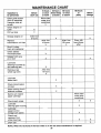
INTEN/ WN CE CHART
Operation to
be performed
| Before |
| eachuse|
10 hours _
or once
a month
30 hours
| three limes)
a season
50 hours В
а season |
400 hours
yearly
— Before
storage |
Clean grille screen
(front & backside)
& engine inlet air
screen
> More often
under dirty
conditions '
Check engine oil _
— Level
Fill fuel tank
x
Change engine oil
After first
“5 hours |
Replace |
transmission oil filter
“After first
10 hours
| After first
|50 hours
XX
Every 100
] hours there:
Re-oil & clean
foam air precleaner
X
x
. after
Check battery
electrolyte level
X
Grease front axle
pivot bolt
x |
Lubricate .
steering knuckles (2) |
and steering arm
Retorque rear
~ wheel lug bolts
After first
10 hours.
Lubricate
brake shaft
Check transmission
oil level |
Clean cooling fins 8
external surfaces
Service air cleaner
paper cartridge
“| More often
“| under dirty
| conditions
Check spark plugs _ |
Lubricate
steering gear housing
~ Lubricate
speed control
linkage cam plates
Check and
regrease front
wheel bearings
Drain fuel
NOTE: When the red hand of the hour meter is in \ the red areas maintenance is required.
26
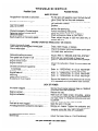
HARD TO START
No gasoline in fuel tank or carburetor
"+ ++. ев
Fuel line or carburetor clogged
Gas filter plugged
Water in gasoline
- Choked improperly. Flooded engine
Defective ignition or loose wiring
Defective battery
Spark plug dirty or improperly gaped
E SN >..."
"+...
€ #« AA
« «4.800 0 0 DR EU a PN AV WS DR Re a DDR.
Possible Remedy
Fill the tank with gasoline; open the fuel shut- off
“valve. Check the fuel line, and carburetor.
Clean the fuel line and carburetor with commer:
cial carburetor cleaner. |
Replace.
Drain the fuel tank and carburetor. Use new fuel
and dry the spark plug.
Follow the starting instructions.
Check the wiring,-spark plug, or breaker.
Check and service. Refer to “BATTERY.”
Clean, adjust the gap to .025 inch (635 mm), or
replace the plug. | |
"ENGINE OPERATES IRREGU LARLY OR KNOCKS
Engine incorrectly timed
Spark plug dirty; wrong gap or wrong type
Poor or weak spark
| Carburetor setting incorrect Cree
Poor grade fuel or water in fuel
Engine overheating ..........................
Engine valves at fault
Engine smokes
т ов пати вн ие в ниве ине ви вание
Oil level will rise due to gasoline
in crankcase . LA 110 8 6 Lee 0 4 8 ua en 000
| Air filter will become oil and fuel soaked
Enginé leaks oil
Mis- fring.
= CE
я. ао вон. я ее ао тен нак вваяа 6
ва чеков
® PF = чт ва вв атнь = = ин я в EE ow WOME aN
» ace зв а Фо в йа фж в’ 4 NT
.…......….".."".
*
Clean, reset the gap, or replace.
Check the breaker points and breaker point open-
ing, spark plug, and wiring.*
Adjust. Refer to “ENGINE AND FUEL SYSTEM.”
. Drain and use a good grade of clean fuel.
| Refer to “ENGINE COOLING AND AIR CLEANER. >
Adjust the carburetor. Check for worn piston and
rings.*
Refer to “OPERATING IN COLD WEATHER.”
Refer to “OPERATING IN COLD WEATHER.”
Refer to “OPERATING IN COLD WEATHER.”
Refer to “OPERATING. IN COLD WEATHER ”
Be sure that dipstick is fully seated and all excess
oil is Squeezed out of pre- ‘cleaner foam element.
LACK OF POWER _
EAN AA EN 6 = 1 4% à 1 1 6 4 5 . —].—.
“ Poor fuel, too rich, or too lean a mixture
Fuel tank air vent clogged....................
‘Air leakage between carburetor and engine
“Incorrect timing or faulty ignition
Brake drags
190. OE Os EF OEE® soe =m
SACAN E EA EEC Y AAA
‘Service the air cleaner element. Refer to “ENGINE
COOLING AND AIR CLEANER.”
Reduce the load.
Make sure air intake screen, shrouding, ‘engine
fins, and grille screen are free of accumulated dirt
and trash. Refer to “ENGINE COOLING AND AIR
CLEANER.” |
Refer to “ENGINE AND FUEL SYSTEM”.
Open the vent in the cap. |
Remove air cleaner. Tighten the carburetor and
- manifold mounting nuts. Replace as instructed in
‘ENGINE COOLING AND AIR CLEANER.”
Adjust the brake. Refer to “CLUTCH-BRAKE”.
“See your authorized Cub Cadet dealer.
Possible Cause
TROUBLE SHOOTING
shroud, cooling fins,or dirty grille screen ........
Lean carburetor adjustment
Qil level incorrect
Possible Remedy
ENGINE OVERHEATS
Insufficient cool air, dirty air intake screen,
Keep the air intake area and cooling fins clean;
Refer to “ENGINE COOLING AND AIR CLEANER.”
- Readjust; Refer to “ENGINE AND FUEL SYSTEM”.
Engine oil level must not be over the “FULL” mark.
or below the “LOW” mark. Refer to “ENGINE AND.
FUEL SYSTEM.”
*See your authorized Cub Cadet dealer.
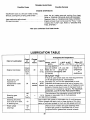
LUBRICATION TABLE
| Anticipated Air Temperature
| Check] Change - - -
Point of Lubrication at at 1 Capacity | | |
Hours | Hours | {Above + 32°F. + 32°F. to 0°F. Below 0°F.
a (0°С.) (0° to —17.1%C) | (- 17.1% C.)
01 |.H. Low Ash En- | 1.H. No. 19
| |Check| | gine Oil SAE-30 [l.H. Low Ash Engine Oil
Engine Crankcase before 30 | 3pt. |Note: Do not Engine Oil SAE-5W-20
| each (1 AL) substitute 10W-30|SAE-10W a or
use or 10W-40 | — | SAE-BW-30
IH Hy-Tran® Fluid” |
(If fluid is used which does not meet requirements
Hydro-drive unit of IH B-6 Specifications, International
mounted on 14 pts. |Harvester Co. will not be responsible for sub-
transmission case 30 Add as | (6.6L) [standard performance such as lack of proper con-
with filter needed | Approx. |trol, power or premature wear out of hydraulic com-
ponents. Failures due to use of improper fluid or
filters are not covered by warranty. For maximum
| protection, use IH Hy-Tran Fluid and IH filters.
| 100 ВЕ — | Two strokes of the lubricator using IH-251H EP
Steering gear or | — | 1.4 Ib. {grease or equivalent No. 2 multi- purpose
housing Yearly (0.1KG) |lithium grease. |
Steering knuckles, Use IH:251H EP grease or equivalent No. 2 multi-purpose
front axle pivot bolt, 10 lithium grease and apply two or three stokes of the lubri-
& steering arm cator or sufficient grease to flush out old grease and dirt.
Front wheel 100 Remove front wheels and pack bearings with
bearings or |H-251H EP grease or equivalent No. 2 multi-
| Yearly |
purpose lithium grease and reinstall wheels.
28
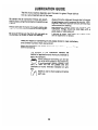
LUBRICA ION GUIDE
The life of any machine depends upon the care it is given. ‘Proper lubrica- |
tion is a very important part of that care.
Be certain that all lubrication fittings are assem-
bled in place, using the lubrication illustrations as
a guide.
Always lubricate the tractor thoroughly before tak-
ing it to the field. Use a pressure \ubricating gun.
Be sure all fittings are free from dirt and paint s so
the lubricant is certain to enter the bearing.
Always force the lubricant through the full length
of each bearing until it emerges at the end, carry-
ing with it the worn lubricant and any dirt that may
have entered the bearing.
Miscellaneous working parts not provided with
lubrication fittings should be oiled daily with a
good grade of lubricating oil.
Lubricant is cheap. Use plenty of it. Worn parts
can be expensive to replace.
Keep your supply of lubricating oil and grease stored in clean containers,
and covered to protect from dust and dirt.
Keep the lubricating gun nozzle clean and wipe dirt from grease fittings
before lubricating.
The. ‘symbols in the illustration
indicate the
method of application and the hourly intervals to
apply the lubricant.
©
Use a pressure lubricating gun and ap-
ply IH 251H EP grease (or equivalent No.
2 multi-purpose lithium grease) suffi-
cient to flush out the old grease: and dirt.
Lubricate at hourly Intervals indicated on sym-
bols.
©
each use.
Dipstick, use to check engine oil before
LUBRICATION GUIDE
Ovivii-vN epis }Чблы
| ‘sanoy G je abueyod 110 JEIHU]
| с я
Hoe |
sepis ujog
6
y | '¿eyea1oy) sinoy 0€ Á1ana pue 8 |
fo)
0
W0}30G 193U97
asn yoea
910469 1938349 | ; /
30
1—Engine filler cap
and dipstick.
2—Steering knuckles (2).
(Both sides)
3—Transmission oil filter.
4—Front Axle pivot bolt.
(Right side)
S— Engine ой drain plug.
6— Transmission oil level
and fitler plug.
7--Transmission oil filter.
8-— Transmission oli fitter,
9-Steering gear housing.
(Center bottom)
Speed Control Linkage
10-Cam pilates.
Miscellaneous
Brake pedal shaft
LUBRICATION GUIDE
Before Each Use
Check the oi! {with the engine stopped) and add sufficient
new oil to bring it to the “FULL” mark on the dipstick. Do
not overfill. Do not operate the engine if the oil level is
below the “LOW” mark on the dipstick.
—After Every 10 Hours of Operation
Use 1H 251H EP grease or equivalent No. 2 multi-purpose
lithium grease and apply sufficient grease to flush out oid
grease and dirt.
NOTE: After the first 10 hours only, remove the ati filter
and replace with a new filter. Refer to “ENGINE AND
FUEL SYSTEM”. Change the oil filter after 50 hours and
every 100 hours of operation thereafter,
Use 1H 251H EP grease or equivalent No. 2 multi-purpase
lithium grease and appiy sufficient grease to flush out ald
grease and dirt. NOTE: It may be necessary to rotate the
front axie to reach the grease fitting.
— After Every 30 Hours of Operation
While the oil is warm, remove the drain plug (5) and drain
all of the oil from the crankcase. Replace the drain plug.
Refill the crankcase with naw oil up to the “FULL” mark
on the oil level gauge. Refer to the “LUBRICATION
~ TABLE” for the proper quantity and viscosity to use.
Check the oil with the engine stopped. Keep the lubricant
up to level plug 6 on the rear of the transmission case,
~ After Every 50 Hours of Operation
NOTE: After the first 50 hours only, remove the oil filter
and replace with a new filter. Refer to “ENGINE AND
FUEL SYSTEM." Change the oii filter every 100 hours of
operation thereafter.
— Every 100 Hours of Operation
Change the oil filler and replace with a new filter. Refer to
“ENGINE AND FUEL SYSTEM.”
Once a year, apply two strokes of the lubricator, using iH
251H EP grease or equivalent No. 2 multi-purpose lithium
grease.
NOTE: To locate the lubrication fitting, turn the front
wheels to the maximum right turn position. Then reach up
under the right $ ide of the tractor frame to locate the fit
ting.
Once a year, apply a small amount of IH 251H EP grease
or equivalent No. 2 multi-purpose lithium grease in the
siois, |
Lubricate the brake pedal shaft and linkage with eight or
ten drops of engine oil, —
NOTE: When the red hand of the hour meter is ín the red areas maintenance is reguired.
31
"SPECIFICATIONS
CAPACITIES
Fuel Tank... PAS O earn ere. a 4 gals. (15.11)
Crankcase . Cee eee Cet ee te ree ee renee ree a 3 pts. (1.4 L)
Transmission case with Hydro- -drive unit mounted ee eee eee 14 pts. (6.6 L)
‘Steeringgearhousing ...............cc iia... a Cee eee RE 1/4 1b. (0.1 KG)
HYDROSTATIC DRIVE a
Speed: Forward ................... PT ....0t08.64 mph (13.89 Km/h)
— Reverse ..... ee Le Ce ee O to 4.25 mph (6.83 Km/h)
ENGINE -
Make and model ................ FO ee RE PS Kohler
- (electric starting) ........…. TN KT17
Cylinders ...... aanaacasenoracore ae EE ee ae ea ae ea de eee PAS 2
Bore ............ aaa. aaa. eee aaa Chee Ce eee aa 3.125-in. (79.4 mm)
Stroke ..... iaa ene A LL La a a ua ee PS ass ee 1204000 .2.750-in. (69.8 MM)
Displacement (cubic inches) Cee ee ee eee 42.18 (691.2 cc)
Engine Speed |
(governed) | |
Low speed ............. RAA eee ea 1200 rpm
High idle speed о | | | В В
(noload) ...... ee eee PA PT ea 3600 rpm
(fullload) ............ enana aaa PE aenaerecrrerorranveraear ene nta one 3350 rpm
‘Valve clearance o
(engine cold) LL ee ae 1 a a AAA aa AA 0 0 a 4 ee a a a La a a a de a aa a 0 6 .008-.011-in. (.203-.279 mm) (intake)
| Е .011-.014 (.279- 355 mm) (exh.)
Ignition .......... eee eee ee eee ieee . . . Battery
Spark plug gap |
(14 mm plug) (Champion RBL-154 or equivalent) ................. RAA 025- in. (.635 mM) gap
Breaker points Ce ee ee a ea a ea 1112200 ace ee .017- .023- in. (432. 584 mm) gap
ELECTRICAL SYSTEM
System voltag@& ................... eee RAR 12 voit neg. ground
Battery...........oeoeeeecrecocereo, ree ere ee eee .1HPRLU
Alternator ................ ee a aaradanrancraneadocarracooerarocrneco aaa 15 amp.
Fuse (cartridge type) (1or2) ............. enana RAA eee eee AGC-10
10 AMP Slow Blow
Headlights | |
all glass, sealed beam units La a ea 0000 PAS Bere. + Батр №. H7610
| 1H Part No. 126 470 C1
Taillight ........... I PEE een. TEE Lamp No. 194
IH Part No. 20 627 R1
BRAKES (Single disc internal transmission brake)
Internal wet brake
TIRE SIZES |
Front. .................. i. Cee ean PS FE ...16x6.50-8
Rear .......... J SE FUT es ...23x10.50-12
Specifications are subject to change without notice.
| de |
SPECIFICATIONS
DIMENSIONS
Tread: | a
Front with 16x6.50-8 tires ........... RAA ee RAA a sac ee 29-in. (737 mm)
Rear with 23 x 10-50- 12 tires eee da ep aa seau e 0» da usa un eae RARE 27.0-in. (686 mm)
“Wheelbase ......... Cheese EE a eae 44-in. (1.12 M)
— Length, overall ......... an anecarecau e. nee... een. Cee 0000 naco. ea 72.0-in. (1.82 M)
Width, overall... area ees Cee ....37.75-in. (959 mm)
Height, over-all (to top of steering wheel) RAA AAA AAA PARA RAS 43-in. (1.09 M)
Groundclearance .............. eee eee. enana 6-in. (152 mM)
— Turning radius ..... aero eee PEE 6.75 ft. (2.06 M)
Specifications are subject to change without notice.
English Unit | | a Metric Equivalent (SI) |
a Area 1
1 square inch (in?) | — 6.45 square centimeter (em?)
1 acre 0.405 hectare(ha)
Force 2
1 pound-force (Ibf) | В 4.45 newton (N)
о Length a
1 foot (ft) a 304. 8 millimeter (mm), 30.5 centimeter (cm),
Coo Е a 0.305 meter (m)
1 inch (in) | Ш 25. 4 millimeter (mm), 2.54 centimeter (cm)
1 mile 1609 meter (m), 1.61 kilometer (km)
Mass )
1 pound (Ib) ~~ 0.454 kilogram (kg)
o Power —— EE
1 horsepower (hp) © 0.746 kilowatt (kW)
Pressure E
1 pound- force per square — 6.89 kilopascal (kPa), 0.00689 megapascal (MPa)
inch, psi (Ibfrin? ) |
Temperature
t degree Fahrenheit (°F) | es 29 едгее Celsius (° C)
ВО Torque |
1 pound-force foot (Ibf-ft) 1.356 newton meter (N-m)
o — Velocity
1 mile per hour (mph) 1.61 kilometer per hour (km/h)
| Volume |
1 US bushel 0.035 cubic meter (m3)
1 US gallon (US gal) | | 3.79 liter (Ly
33
Accidents
can be prevented
with your help
No accident-prevention program can be suc-
cessful without the wholehearted co-operation of
the person who is directly responsible 1 for the
operation of equipment.
To read accident reports trom al! over the coun-
try is to be convinced that a Jarge number of ac-
cidents can be prevented only by the operator an-
ticipating the result before the accident is caused
and doing something about it. No power-driven
equipment, whether it be transportation or pro-
cessing, whether-it be on the highway, in the
harvest field or in the industrial plant, can be safer
than the man who is at the controls. If accidents
are to be prevented—and they can be prevented —
it will be done by the operators who accept a full
measure of their responsibility.
It Is true that the designer, the manufacturer,
the safety engineer can help; and they will help,
but their combined efforts can be wiped out by a
single careless act of the operator.
It is said that “the best kind of a safety device is
a careful operator.” We ask you to be that kind of
an operator.