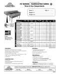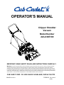
1
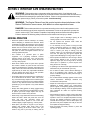
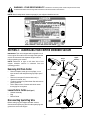
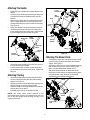
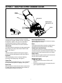
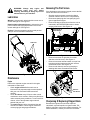
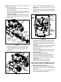
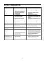
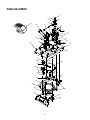
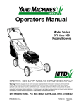
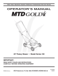
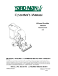
OPERATOR’S MANUAL
Chipper Shredder
Vacuum
Model Number
24A-030E100
IMPORTANT: READ SAFETY RULES AND INSTRUCTIONS CAREFULLY
Warning: This unit is equipped with an internal combustion engine and should not be used on or near any unimproved forestcovered, brush-covered or grass-covered land unless the engine’s exhaust system is equipped with a spark arrester meeting
applicable local or state laws (if any). If a spark arrester is used, it should be maintained in effective working order by the operator.
In the State of California the above is required by law (Section 4442 of the California Public Resources Code). Other states may have
similar laws. Federal laws apply on federal lands. A spark arrester for the muffler is available through your nearest engine authorized
service dealer or contact the service department, P.O. Box 368023 Cleveland, Ohio 44136-9722.
CUB CADET CORP. P.O. BOX 368023 CLEVELAND, OHIO 44136-9722
PRINTED IN U.S.A.
FORM NO. 770-10231A.fm
(2/00)
TABLE OF CONTENTS
Content
Page
Important Safe Operation Practices................................................................... 3
Assembling Your Chipper Shredder Vacuum .................................................... 5
Know Your Chipper Shredder Vacuum .............................................................. 7
Operating Your Chipper Shredder Vacuum ....................................................... 8
Maintaining Your Chipper Shredder Vacuum..................................................... 9
Troubleshooting ................................................................................................. 12
Parts List............................................................................................................ 14
FINDING MODEL NUMBER
This Operator’s Manual is an important part of your new chipper shredder vacuum. It will help you
assemble, prepare and maintain the unit for best performance. Please read and understand what it says.
Before you start assembling your new equipment, please locate the model plate on the
equipment and copy the information from it in the space provided below. The information on
the model plate is very important if you need help from our Customer Support Department or
an authorized dealer.
•
You can locate the model number by looking down at the rear of the chipper shredder vacuum. A
sample model plate is explained below. For future reference, please copy the model number and the
serial number of the equipment in the space below.
(Model Number)
(Serial Number)
CUB CADET CORP.
Copy the model number here:
Copy the serial number here:
P.O. BOX 368023
CLEVELAND, OHIO 44136
CALLING CUSTOMER SUPPORT
If you have difficulty assembling this product or have any questions regarding the controls, operation or
maintenance of this unit, please call the Customer Dealer Referral Line.
Call 1- (800)-528-1009 to reach the Customer Dealer Referral Line. Please have your unit’s
model number and serial number ready when you call. See previous section to locate this
information.
For more details about proper lawn care, visit our website at www.cubcadet.com
2
SECTION 1: IMPORTANT SAFE OPERATION PRACTICES
WARNING: This symbol points out important safety instructions which, if not followed, could
endanger the personal safety and/or property of yourself and others. Read and follow all instructions in
this manual before attempting to operate this machine. Failure to comply with these instructions may
result in personal injury. When you see this symbol - heed its warning.
WARNING: The Engine Exhaust from this product contains chemicals known to the
State of California to cause cancer, birth defects or other reproductive harm.
DANGER: This machine was built to be operated according to the rules for safe operation in this
manual. As with any type of power equipment, carelessness or error on the part of the operator can
result in serious injury. This machine is capable of amputating hands and feet and throwing objects.
Failure to observe the following safety instructions could result in serious injury or death.
GENERAL OPERATION
nozzle, chipper chute or discharge opening as the
rotating impeller can cause serious injury.
• Read this operator’s manual carefully in its entirety
before attempting to assemble this machine. Read,
understand, and follow all instructions on the machine
and in the manual(s) before operation. Be completely
familiar with the controls and the proper use of this
machine before operating it. Keep this manual in a
safe place for future and regular reference and for
ordering replacement parts.
• Do not operate this machine while under the
influence of alcohol or drugs.
• If it is necessary for any reason to unclog the feed
intake or discharge openings or to inspect or repair
any part of the machine where a moving part can
come in contact your body or clothing, stop the
machine, allow it to cool, disconnect the spark plug
wire from the spark plug and ground against the
engine before attempting to unclog, inspect or repair.
• This machine is a precision piece of power
equipment, not a plaything. Therefore, exercise
extreme caution at all times. Your unit has been
designed to chip, shred, vacuum, or blow. Do not use
it for any other purpose.
• Never operate unit without the vacuum bag or blower
chute properly affixed to unit. To avoid a thrown
object the large open end of bag must be securely
closed prior to operation to prevent objects from
being thrown out of the bag.
• Never allow children under 16 years old to operate
this machine. Children 16 years old and over should
read and understand the operation instructions and
safety rules in this manual and should be trained and
supervised by an adult. Only responsible individuals
who are familiar with these rules of safe operation
should be allowed to use this machine.
• If operating in the blower mode (optional blower chute
attachment may be included with your unit):
• Do not stand or walk in front of blower discharge or
aim it at bystanders, pets, vehicles, ect. Objects
thrown out the discharge can cause personal injury or
property damage.
• Thoroughly inspect the area where the equipment is
to be used. Remove all stones, sticks, wire, bones,
toys, and other foreign objects which could be tripped
over or picked up and thrown by the chipper shredder
vacuum in any direction which could cause serious
personal injury to the operator or any others allowed
in the area.
• Do not direct blower discharge against a wall or other
vertical obstructions. Discharge materials may
ricochet back at the operator.
• Adjust vac nozzle height to highest position to reduce
likelihood of heavier objects (e.g., small stones,
pieces of glass or metal) being picked up and thrown
out the discharge. Raising nozzle to highest position
also maximizes air intake for improved blowing
performance.
• Always wear safety glasses or safety goggles during
operation or while performing an adjustment or repair,
to protect eyes from foreign objects that may be
thrown from the machine in any direction.
• Never attempt to remove or empty vacuum bag when
engine is running. Shut the engine off and wait for the
impeller to come to a complete stop before removing
the bag. The impeller continues to rotate for a few
seconds after the engine is shut off. Never place any
part of the body in the impeller area until you are sure
the impeller has stopped rotating.
• Wear sturdy, rough-soled work shoes and close-fitting
slacks and shirts. Shirts and pants that cover the
arms and legs and steel-toed shoes are
recommended. Never operate a unit in bare feet,
sandals, slippery or light weight (e.g. canvas) shoes.
• Never place your hands or any part of your body or
clothing near rotating parts. Keep clear of the
discharge opening at all times. Never insert your
hands or any part of your body or clothing into the
• Keep all guards and safety devices in place and
operating properly.
3
SAFE HANDLING OF GASOLINE:
• Do not allow an accumulation of processed material
to build up in the discharge area as this will prevent
proper discharge.
To avoid personal injury or property damage use extreme
care in handling gasoline. Gasoline is extremely flammable
and the vapors are explosive. Serious personal injury can
occur when gasoline is spilled on yourself or your clothes
which can ignite. Wash your skin and change clothes
immediately.
• When feeding material into the chipper, do not stand
with your face or body directly in front of the chipper
chute. Stand to one side. Material being feed may
bounce back out of the chute and cause personal
injury.
• Use only an approved gasoline container.
• If the cutting mechanism strikes a foreign object or if
your machine should start making an unusual noise
or vibration, immediately stop the engine, wait for
impeller to come to a complete stop, and disconnect
the spark plug wire and ground against the engine.
Follow steps listed below:
•
• Extinguish all cigarettes, cigars, pipes, and other
sources of ignition.
• Never fuel machine indoors because flammable
vapors will accumulate in the area.
• Never remove gas cap or add fuel while the engine is
running. Allow engine to cool at least two minutes
before refueling.
Inspect for damage.
• Repair or replace any damaged parts prior to
continuing operation.
• Never over fill fuel tank. Fill tank to no more than 1/2
inch below bottom of filler neck to provide space for
fuel expansion.
• Check for any loose parts and tighten to assure
continued safe operation.
• Replace gasoline cap and tighten securely.
• Muffler and engine become hot and can cause a
burn. Do not touch.
• If gasoline is spilled, wipe it off the engine and
equipment. Move unit to another area. Wait 5 minutes
before starting the engine.
• Only use parts and accessories made for this
machine by the manufacturer. Failure to do so, can
result in personal injury.
• Never store the machine or fuel container inside
where there is an open flame, spark, or pilot light as
on a gas water heater, space heater, furnace, clothes
dryer or other gas appliances.
• If situations occur which are not covered in this
manual, use care and good judgment. Contact your
dealer for assistance. Telephone 1-800-800-7310 for
the name of your nearest dealer.
• To reduce fire hazard, keep the machine free of
grass, leaves, or other debris build-up. Clean up oil or
fuel spillage and remove any fuel soaked debris.
CHILDREN
• Allow machine to cool at least 5 minutes before
storing.
Tragic accidents can occur if the operator is not alert to the
presence of children. Children are often attracted to the
chipping and vacuum activity. They do not understand the
dangers. Never assume that children will remain where you
last saw them.
GENERAL SERVICE
• Never run an engine indoors or in a poorly ventilated
area. Engine exhaust contains carbon monoxide, an
odorless and deadly gas.
• Keep children out of the work area and under the
watchful care of a responsible adult other than the
operator.
• Before cleaning, repairing, or inspecting, make
certain the impeller and all moving parts have
stopped. Disconnect the spark plug wire and ground
against the engine to prevent unintended starting.
• Be alert and turn the machine off if a child enters the
area.
• Before and while moving backwards, look behind and
down for small children.
• Keep all nuts, bolts, and screws tight to be sure the
equipment is in safe working condition.
• Use extreme care when approaching blind corners,
shrubs, trees, or other objects that may obscure your
vision of a child who may run into the machine.
• Never tamper with safety devices. Check their proper
operation regularly.
• Keep children away from hot or running engines.
They can suffer burns from a hot muffler.
• After striking a foreign object, immediately stop the
engine, disconnect the spark plug wire and ground
against the engine. Thoroughly inspect the machine
for any damage. Repair the damage before starting
and operating.
• Never allow children under age 16 to operate this
machine. Children 16 years of age and over should
read and understand the operation instructions and
safety rules in this manual and should be trained and
supervised by an adult.
• Do not change the engine governor setting or
overspeed the engine.
• Maintain or replace safety and instruction labels, as
necessary.
4
WARNING - YOUR RESPONSIBILITY: Restrict the use of this power machine to persons who read,
understand and follow the warnings and instructions in this manual and on the machine.
NOTE: Not all safety labels shown may apply to your chipper shredder vacuum.
SECTION 2: ASSEMBLING YOUR CHIPPER SHREDDER VACUUM
IMPORTANT: This unit is shipped without gasoline or oil
in the engine. Be certain to service engine with gasoline
and oil as instructed in the separate engine manual
before operating your mower.
Upper
Handle
Rope
Guide
NOTE: Reference to right or left hand side of the
chipper shredder vacuum is observed from the
operating position.
Removing Unit From Carton
•
•
•
•
Blower Chute
Remove staples, break glue on top flaps, or cut
tape at carton end and peel along top flap to open
carton.
Remove loose parts if included with unit (i.e.,
operator’s manual, etc.)
Cut along corners, lay carton down flat, and remove
packing material.
Roll or slide unit out of carton and check carton
thoroughly for loose parts.
Wing
Nut
Wing
Nuts
Bag
Lower
Handle
Loose Parts In Carton (See Figure 1)
•
•
•
Handle Assembly
Bag
Blower Chute
Disconnecting Spark Plug Wire
Wing
Nuts
Before setting up your chipper shredder vacuum,
disconnect the spark plug wire from the spark plug and
ground to a stud on the engine.
Carriage
Screw
Figure 1
5
Attaching The Handle
•
•
•
•
•
Lower
Handle
Unfold the upper handle until it aligns with the lower
handle.
Secure the two handles by tightening the wing nuts
(carriage bolts must be seated properly into the
handle).
Remove the hairpin clips from the handle brackets
on the chipper shredder vacuum and remove the
carriage bolts and wing nuts from the lower handle.
See Figure 2.
Place each bottom hole in lower handle over pins
on handle brackets and secure with hairpin clips.
Insert carriage bolts thru upper hole in lower handle
from the outside and secure with wing nuts.
Wing Nuts
Bag
Handle
Bag
Clip
Stud
Locking
Rod
Front
Tab
Strap
Front
Tab
To Engine
Lower
Handle
Safety
Switch
Carriage
Bolt
Stud
Pin
Hairpin
Clip
Figure 3
Handle
Brackets
Attaching The Blower Chute
•
Figure 2
•
•
Loosen the wing nut that secures the rope guide to
the right side of upper handle.
Pull the starter rope out of the engine slowly and
slip the starter rope into the rope guide. Tighten the
wing nut.
•
•
Attaching The Bag
•
•
•
•
Grasp bag handle with one hand and pull locking
rod on mounting bracket with other hand toward
engine. See Figure 3.
Slip bag over the rim of the discharge opening and
release locking rod to secure bag in place.
Place the straps on the bag over the lower handle,
hooking them on the studs.
Snap bag clip to the top of the lower handle.
Grasp blower chute with one hand and pull locking
rod on mounting bracket with other hand toward
engine. See Figure 4.
Slip blower chute over rim of the discharge opening
and release locking rod to secure chute in place.
Make sure the safety switch button is fully
depressed by the front tab on the blower chute.
Raise the nozzle height to the highest setting when
using the blower chute. Refer to nozzle height
adjustment in the OPERATION section.
Front
Tab
Blower
Chute
Front
Tab
NOTE: The safety switch button attached to the
mounting bracket must be fully depressed by the front
tab on the bag handle when securing the bag or the
engine will not start.
Safety
Switch
Locking
Rod
Figure 4
6
SECTION 3: KNOW YOUR CHIPPER SHREDDER VACUUM
Starter
Handle
Bag
Bag Handle
Nozzle Height
Adjustment Lever
Chipper
Chute
Nozzle
Blower Chute
Figure 5
Nozzle Height Adjustment Lever
Read this operator’s manual and safety rules before
operating your chipper shredder vacuum. Compare the
illustrations in Figure 5 with your unit to familiarize
yourself with the location of various controls and
adjustments. Save this manual for future reference.
Used to adjust the nozzle ground clearance ranging
approximately 5/8” to 3 3/4”.
Nozzle
Yard waste such as leaves and pine needles can be
vacuumed up through the nozzle for shredding.
Starter Handle
The starter handle is attached to the right upper handle.
Stand behind unit and pull the starter handle to start
engine. See Figure 5.
Throttle Control Lever (Not Shown)
The throttle control lever is located on the engine. It
controls the engine’s speed and stops the engine. See
separate engine manual packed with unit for details.
Bag
Collects shredded material fed through the chipper
chute or vacuumed through the nozzle. See Figure 5.
Engine Controls
See the separate engine manual for the location and
function of the controls on the engine.
Bag Handle
Used to grasp bag in order to assist in attaching,
removing, and emptying bag. See Figure 5.
Stopping Engine
Chipper Chute
•
Allow twigs and small branches up to 1 1/2” in diameter
to be fed into the impeller for chipping. See Figure 5.
•
Blower Chute
When attached to unit the blower chute is used to blow
or scatter yard waste such as leaves, pine needles, or
small twigs across yard. See Figure 5.
7
Move throttle control lever to STOP or OFF
position.
Disconnect spark plug wire from spark plug and
ground against the engine.
SECTION 4: OPERATING YOUR CHIPPER SHREDDER VACUUM
WARNING: The operation of any chipper
shredder vacuum can result in foreign
objects being thrown into the eyes, which
can damage your eyes severely. Always
wear the safety glasses provided with this
unit or eye shields before chipping or
blowing and while performing any
adjustments or repairs.
•
•
•
•
Grasp bag handle with one hand and pull lock rod
on mounting bracket with other hand toward engine
to release.
Remove bag from rim of the discharge opening.
Refer to Figure 3.
Twist the two buttons on the back of the bag to
unlock and empty contents. See Figure 6.
Hold bag handle and bag clip while emptying the
contents.
Gas And Oil Fill-Up
Service the engine with gasoline and oil as instructed in
the separate engine manual packed with your chipper
shredder vacuum. Read instructions carefully.
Bag
Clip
Bag
Handle
WARNING: Never fill fuel tank indoors with
engine running or until the engine has
been allowed to cool for at least two
minutes after running.
Buttons
Starting Engine
•
•
•
•
•
•
•
Attach spark plug wire to spark plug. Make certain
the metal cap on the end of the spark plug is
fastened securely over the metal tip on the spark
plug.
Make sure safety switch wire is connected to
engine and properly grounded.
Engines with choke lever:
Move choke lever on engine to CHOKE position. (A
warm engine may not require choking).
Engines with primer:
Prime engine as instructed in separate engine
manual.
The throttle control is located on the engine. Move
engine throttle control lever to FAST or ON position.
Stand behind unit, grasp starter handle and pull
rope out slowly until engine reaches start of
compression cycle (rope will pull slightly harder at
this point).
Pull rope with a rapid, continuous, full arm stroke.
Keep a firm grip on starter handle. Let rope rewind
slowly.
Repeat previous steps until engine fires. When
engine starts, move choke control (if equipped)
gradually to RUN position.
Strap
Figure 6
To Remove Blower Chute
•
•
Using the Chipper Shredder Vacuum
Place both hands on top of upper handle to push unit
over yard waste. Yard waste such as leaves and pine
needles can be vacuumed up through the nozzle for
shredding. After material has been shredded by the flail
blades on the impeller assembly, it will be discharged
into catcher bag or through blower chute. Do not
attempt to shred or chip any material other than
vegetation found in a normal yard (i.e. branches,
leaves, twigs, ect.) Avoid fibrous plants such as tomato
vines until they are thoroughly dried out. Materials such
as stalks or heavy branches up to 1 1/2” in diameter
may be fed into the chipper chute. See Figure 7.
WARNING: Never run the engine indoors
or in a poorly ventilated area. Engine
exhaust contains carbon monoxide, an
odorless and deadly gas.
To Empty Bag
•
Grasp blower chute with one hand and pull lock rod
on mounting bracket with other hand toward engine
to release. Refer to Figure 4.
Remove blower chute from rim of the discharge
opening.
Unhook bag straps from the lower handle and
unsnap bag clip from the top of lower handle.
See Figure 6.
8
Nozzle Height Adjustment
The nozzle can be adjusted to any five positions,
ranging from 5/8” to 3 3/4” ground clearance. The
nozzle height has to be adjusted according to the
conditions. Move the height adjustment levers forward
or backward to adjust the nozzle upwards or
downwards. See Figure 8.
NOTE: In general, raise the nozzle height to vacuum a
think layer of leaves or to operate with the blower chute
and lower the nozzle height for smoother surfaces.
Chipper
Chute
Nozzle
Figure 7
IMPORTANT: The flail screen is located inside the
housing in the discharge area. If the flail screen
becomes clogged, remove and clean as instructed in
SECTION 5: MAINTAINING YOUR CHIPPER
SHREDDER VACUUM. For best performance, it is also
important to keep the chipper blade sharp.
Height
Adjustment
Lever
WARNING: Do not at any time make any
adjustments without first stopping engine
and disconnecting spark plug wire.
Nozzle
Figure 8
SECTION 5: MAINTAINING YOUR CHIPPER SHREDDER VACUUM
MAINTENANCE
SCHEDULE
Be
for
ee
ac
hu
se
Ev
er
y2
5h
ou
rs
Ev
er
y5
0h
ou
Ev
rs
er
y1
00
ho
ur
On
s
ce
as
ea
so
Be
n
for
es
tor
ag
e
Customer Responsibilities
PRODUCT
Lubricate Wheels
Lubricate Nozzle Levers
Lubricate Locking Rod
Check Chipper Blade
ENGINE
Change Oil
Check Air Filter
Clean Engine
Check Spark Plug
9
SERVICE
DATES
Removing The Flail Screen
WARNING: Always stop engine and
disconnect spark plug wire before
cleaning, lubricating or doing any kind of
maintenance on your machine.
If the discharge area becomes clogged, remove the flail
screen and clean area as follows:
•
Lubrication
•
Wheels: Lubricate each wheel shoulder screw once a
season with light oil. See Figure 9.
•
Nozzle height adjustment levers: Lubricate the pivot
points of the nozzle height adjustment levers once a
season with light oil. See Figure 9.
Stop the engine and make certain the chipper
shredder vacuum has come to a complete stop.
Disconnect spark plug wire from spark plug and
ground against the engine.
Remove the bag or blower chute from the unit as
instructed in the OPERATION section to obtain
access to flail screen. See Figure 10.
Hex Screw &
Flat Washer
Engine: Follow the separate engine manual packed
with you unit for lubrication instructions.
Lubricate
Lock Nut
Flail Screen
Figure 10
•
•
•
Remove hex screw on right side of unit that
attaches to the fail screen. See Figure 11.
Remove hex screw and flat washer on top of rear
housing mounting bracket and the lock nut that
secures flail screen. See Figure 10.
Remove and clean the screen by scraping or
washing with water. Reinstall the flail screen.
Figure 9
Maintenance
Engine
Refer to the separate engine manual for all engine
maintenance instructions.
•
•
•
Check engine oil level before each use as
instructed in the separate engine manual packed
with your unit. Read and follow instructions
carefully.
Clean air cleaner every 25 hours under normal
conditions or once a season. Clean every few hours
under extremely dusty conditions. To service the air
cleaner, refer to the separate engine manual
packed with your unit.
The spark plug should be cleaned and the gap
reset once a season. Check engine manual for
correct plug type and gap specifications.
Remove
Hex Screw
Figure 11
Sharpening Or Replacing Chipper Blade
Because the engine on this unit has a tapered
crankshaft, a special impeller tool (part number 7530638) is required to remove the impeller assembly. For
further assistance, contact your local service dealer.
10
NOTE: When tipping the unit, empty the fuel tank and
keep spark plug side up.
•
•
•
•
Disconnect the spark plug wire and ground it away
from the spark plug.
Remove the front hubcaps, shoulder screws, wave
washers, and bell washers that attach to the front
wheels. See Figure 12.
Remove the shoulder screws that go through the
pivot arms and height bracket adjusters to the front
support brace.
Pivot
Arm
•
Remove lock nut that secures flail screen to the
lower housing. The flail screen does not have to be
removed.
Remove the hex bolt, lock washer, and flat washer
that secure the impeller assembly to the crankshaft.
See Figure 14.
Upper
Housing
Chipper
Blade
Impeller
Assembly
Hex Bolt
Lock Washer
Flat Washer
Shoulder
Bell
Screw
Washer
Flail
Blade
Hubcap
Height
Bracket
Adjuster
BOTTOM VIEW
Figure 14
Shoulder
Screw
•
Wave Washer
Figure 12
•
•
Remove the three screws on the upper housing
that secure the nozzle cover and the nine screws
that secure the lower housing the upper housing.
See Figure 13.
•
•
•
•
•
Apply lubricant to the threads of impeller removal
tool and then thread the tool into the crankshaft.
Stop when the impeller assembly can move on the
crankshaft.
Remove the impeller assembly from the crankshaft.
Unthread the impeller removal tool from the
impeller assembly.
Remove the blade using a 3/16” allen wrench on
the outside of the blade and 1/2” wrench on the
impeller assembly.
Replace or sharpen chipper blade.
When sharpening blade, protect hands by using
gloves and follow the original angle of grind.
Reassemble by performing the previous steps in
reverse order.
Tighten blade screws to 210-250 in-lbs.
Tighten impeller bolt to 375-425 in-lbs.
Storing Your Chipper Shredder Vacuum
•
•
•
Lower
Housing
Screws
Nozzle
Screws
•
Figure 13
11
Clean the equipment thoroughly.
Wipe equipment with a oiled rag to prevent rust.
Refer to engine manual for correct engine storage
instructions
Store unit in a clean, dry area. Do not store next to
corrosive materials such as fertilizer.
SECTION 6: TROUBLESHOOTING
Problem
Engine fails to start
Cause
Remedy
1. Spark plug wire disconnected.
2. Fuel tank empty or stale fuel.
3. Throttle control lever not in correct
starting position. (If Equipped)
4. Choke not in CHOKE position.
5. Blocked fuel line.
6. Faulty spark plug.
1. Connect wire to spark plug.
2. Fill tank with clean, fresh gasoline.
3. Move throttle lever to FAST position.
1. Spark plug wire loose.
2. Unit running on CHOKE.
4. Water or dirt in fuel system.
5. Dirty air cleaner.
6. Carburetor out of adjustment.
1. Connect and tighten spark plug wire.
2. Move choke lever (if equipped) to OFF
position.
3. Clean fuel line; fill tank with clean, fresh
gasoline
4. Drain fuel tank. Refill with fresh fuel.
5. Clean or replace air cleaner.
6. See authorized service dealer.
Too much vibration
1. Loose parts or damaged impeller.
1. See authorized service dealer.
Engine overheats
1. Engine oil level low.
2. Dirty air cleaner.
3. Carburetor not adjusted properly.
1. Fill crankcase with proper oil.
2. Clean or replace air cleaner.
3. See authorized service dealer.
Engine runs erratic
3. Blocked fuel line or stale fuel.
4. Move choke to CHOKE position.
5. Clean fuel line.
6. Clean, adjust gap, or replace.
Occasional skip (hesitates) 1. Spark plug gap too close.
at high speed
1. Adjust gap to .030”.
Unit does not discharge
1. Stop engine immediately and
disconnect spark plug wire. Clean flail
screen and inside of discharge opening.
2. Stop engine and disconnect spark plug
wire. Remove lodged object.
3. Always run engine at full throttle.
4. Empty bag.
1. Discharge chute clogged.
2. Foreign object lodged in impeller.
3. Low engine RPM
4. Vacuum bag is full.
Rate of discharge slows
1. Low engine RPM.
considerably or
2. Chipper blade dull.
composition of discharged
material changes.
1. Always run engine at full throttle.
2. Replace chipper blade or see your
authorized service dealer.
NOTE: For repairs beyond the minor adjustments listed above, contact your nearest authorized service dealer.
12
NOTES
13
Model 24A-030E100
1
2
3
41
4
39
12
5
11
6
8
10
7
9
13
13
14
17
19
18
15
7
16
20
5
7
21
16
22
23
25
24
26
27
30
28
31
29
32
33
34
35
36
36
37
38
36
14
Model 24A-030E100
Ref.
No.
1.
2.
3.
4.
5.
6.
7.
8.
9.
10.
11.
12.
13.
14.
15.
16.
17.
18.
19.
20.
21.
Part No.
725-1700
725-3166
710-0224
629-0920
710-0604
714-0104
736-0264
732-0962
781-0778
747-1153
710-3008
681-0122
726-0454
736-0607
710-0502A
710-0969
710-3195
710-3025
710-0604A
781-0720
710-1054
Ref.
No.
Part Description
Switch Cover
Safety Switch
Hex Washer Screw #10-16 x .50
Wire Harness
Hex Washer Screw 5/16-18 x .625
Cotter Pin
Flat Washer.330 ID x.630 OD
Compression Spring
Mounting Bracket
Lock Rod
Hex Cap Screw 5/16-18 x .75
Chipper Chute Assembly
U-Clip Lock Nut 5/16-18
External Lock Washer 5/16
Hex Washer Screw 3/8-16 x 1.25
Screw #12-16 x 1.0
Hex Cap Screw 5/16-18 x 4.5
Hex Cap Screw 5/16-18 x .625
Hex Washer Screw 5/16-18 x .625
Upper Housing
Hex Screw 5/16-24 x 1.0
22.
23.
24.
25.
26.
27.
28.
29.
30.
31.
32.
33.
34.
35.
36.
37.
38.
39.
40.
41.
NOTE: For painted parts, please refer to
the list of color codes below. Please add the
applicable color code, wherever needed, to
the part number to order a replacement part.
For instance, if a part, numbered 700-xxxx,
is painted Cub Yellow, the part number to
order would be 700-xxxx-0498.
Cub Yellow: 0498
Cub Beige: 0499
Powder Black: 0637
15
Part No.
781-0490
736-0119
712-0411
681-0152
719-0329
781-0735
711-1401
715-0166
736-0247
736-0217
710-0818
681-0154
710-3038
781-0721
712-3004A
731-1905
712-0158
751B281440
710-1256
731-1613
Part Description
Chipper Blade
Lock Washer 5/16
Hex Lock Nut 5/16-24
Impeller Assembly
Flail Blade
Pin Clip
Clevis Pin
Spiral Pin
Flat Washer.375 ID x 1.25 OD
Lock Washer 3/8
Hex Cap Screw 3/8-24 x 2.0
Screen Assembly
Hex Cap Screw 5/16-18 x .875
Lower Housing
Lock Nut 5/16-18
Nozzle Cover
Lock Nut 5/16-18
Shroud
Screw #8-18 x 1.25
Safety Switch Cover
Model 24A-030E100
1
2
4
3
5
7
35
5
8
6
9
11
10
9
11
13
12
15
14
12
16
17
19
12
12
14
23
17
25
26
29
22
33
21
18
30
14
18
17
20
27
34
28
31
32
33
21
16
Model 24A-030E100
Ref.
No.
1.
2.
3.
4.
5.
6.
7.
8.
9.
10.
11.
12.
13.
14.
15.
16.
17.
Part No.
720-0295
749-0438C
720-0279
710-1205
720-0276
710-1174
749-0907A
664-0090
711-1293
712-0397
710-0703
726-0453
781-0777
712-3004A
714-0104
681-0155
681-0156
710-3025
Ref.
No.
Part Description
Foam Grip
Upper Handle
Knob
Eye Bolt
Handle Knob 5/16-18
Carriage Bolt
Lower Handle
Bag Assembly
Studs
Wing Nut 1/4-20
Carriage Screw 1/4-20 x .75
Lock U-Clip Nut 3/8-16
Rear Wheel Support Brace
Flange Lock Nut 5/16-18
Cotter Pin
Handle Bracket Ass”y LH
Hndle Brkt Ass”y RH (Not Shown)
Hex Cap Screw 5/16-18 x .625
18.
19.
20.
21.
22.
23.
25.
26.
27.
28.
29.
30.
31.
32.
33.
34.
35.
17
Part No.
736-0105
734-1992
738-1015
731-0982A
781-0725
781-0765
781-0766
748-0417
747-1100
738-1017
732-0864
710-0653
782-0578
710-0642
734-1978
736-0232
738-0213
631-0090
Part Description
Bell Washer.401 ID x.870 OD
Wheel 9 x 2
Shoulder Screw 3/8-16
Hubcap
Front Wheel Support Brace
Hgt Bracket Adjuster LH
Height Brkt Adj RH (Not Shown)
Pivot Arm
Handle Height Adjuster
Shoulder Screw 3/8-16
Height Adjuster Plate Spring
Hex Washer Screw 1/4-20 x .375
Spring Lever Support Bracket
Hex Washer Screw 1/4-20 x .75
Wheel 8 x 2
Wave Washer .531 ID x .781 OD
Shoulder Screw
Blower Chute Assembly
18
19
MANUFACTURER’S LIMITED WARRANTY FOR:
TWO-YEAR RESIDENTIAL
ONE-YEAR COMMERCIAL
Proper maintenance of your Cub Cadet equipment is the owner’s responsibility. Follow the instructions in your
operator’s manual for correct lubricants and maintenance schedule. Your Cub Cadet dealer carries a
complete line of quality lubricants and filters for your equipment’s engine, transmission, chassis and
attachments.
Riding mowers, lawn tractors, garden tractors, Cub Cadet
attachments and home maintenance products
This limited warranty for residential users, covers any defect in materials or workmanship in your Cub Cadet
equipment for two years from the date of purchase for the first user purchaser. We will replace or repair any
part or parts without charge through your authorized Cub Cadet dealer.
Batteries have a one-year prorated limited warranty with 100% replacement during the first three months.
V-belts for either the traction drive or any attachments are covered for one year only.
Cub Cadet equipment used commercially is warranted for one year only.
(Commercial use is defined as either having hired operators or used for income producing purposes.)
Items not covered
The warranty does not cover routine maintenance items such as lubricants, filters (oil, fuel, air and hydraulic),
cleaning, tune-ups, brake and/or clutch inspection, adjustments made as part of normal maintenance, blade
sharpening, set-up, abuse, accidents and normal wear. It does not cover incidental costs such as transporting
your equipment to and from the dealer, telephone charges or renting a product temporarily to replace a
warranted product.
There is no other express warranty.
How to obtain service
Contact your authorized Cub Cadet servicing dealer who sold you your Cub Cadet equipment. If this dealer is
not available, see the Consumer Yellow Pages under “lawn mowers” for the name of a dealer near you.
If you need further assistance in finding an authorized Cub Cadet servicing dealer, contact:
Cub Cadet Corporation
Post Office Box 368023
Cleveland, Ohio 44136
How does state law apply?
This limited warranty gives you specific legal rights, and you may also have other rights which vary from state
to state.