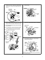
1
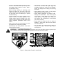
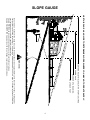
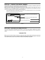
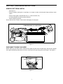
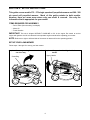
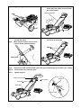
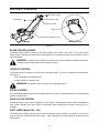
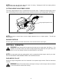
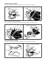
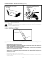
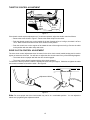
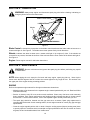
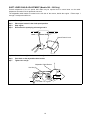
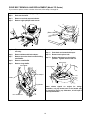
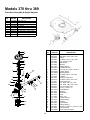
Operators Manual
Model Series
370 thru 389
Rotary Mowers
IMPORTANT: READ SAFETY RULES AND INSTRUCTIONS CAREFULLY
Warning: This unit is equipped with an internal combustion engine and should not be used on or near any unimproved forestcovered, brush-covered or grass-covered land unless the engine’s exhaust system is equipped with a spark arrester meeting
applicable local or state laws (if any). If a spark arrester is used, it should be maintained in effective working order by the operator.
In the State of California the above is required by law (Section 4442 of the California Public Resources Code). Other states may have
similar laws. Federal laws apply on federal lands. A spark arrester for the muffler is available through your nearest engine authorized
service dealer or contact the service department, P.O. Box 368022 Cleveland, Ohio 44136-9722.
MTD PRODUCTS INC. P.O. BOX 368022 CLEVELAND, OHIO 44136-9722
PRINTED IN U.S.A.
FORM NO. 770-0420A
10/97
SECTION 1: IMPORTANT SAFE OPERATION PRACTICES
WARNING: THIS SYMBOL POINTS OUT IMPORTANT SAFETY INSTRUCTIONS WHICH, IF
NOT FOLLOWED, COULD ENDANGER THE PERSONAL SAFETY AND/OR PROPERTY OF
YOURSELF AND OTHERS. READ AND FOLLOW ALL INSTRUCTIONS IN THIS MANUAL
BEFORE ATTEMPTING TO OPERATE YOUR LAWN MOWER. FAILURE TO COMPLY WITH
THESE INSTRUCTIONS MAY RESULT IN PERSONAL INJURY. WHEN YOU SEE THIS
SYMBOL, HEED ITS WARNING.
WARNING: The Engine Exhaust from this product contains chemicals known to
the State of California to cause cancer, birth defects or other reproductive harm.
DANGER: Your lawn mower was built to be operated according to the rules for safe operation in
this manual. As with any type of power equipment, carelessness or error on the part of the operator
can result in serious injury. This lawn mower is capable of amputating hands and feet and throwing
objects. Failure to observe the following safety instructions could result in serious injury or death.
1. GENERAL OPERATION
• Always wear safety glasses or safety goggles
during operation or while performing an adjustment
or repair, to protect eyes from foreign objects that
may be thrown from the machine in any direction.
• Read this operator’s manual carefully in its entirety
before attempting to assemble this machine. Read,
understand, and follow all instructions on the
machine and in the manual(s) before operation. Be
completely familiar with the controls and the proper
use of this machine before operating it. Keep this
manual in a safe place for future and regular
reference and for ordering replacement parts.
• Thoroughly inspect the area where the equipment
is to be used. Remove all stones, sticks, wire,
bones, toys and other foreign objects which could
be picked up and thrown by the mower in any
direction and cause serious personal injury to the
operator or any others allowed in the area. Plan
your mowing pattern to avoid discharge of material
toward roads, sidewalks, bystanders and the like.
To help avoid a thrown objects injury, keep
children, bystanders and helpers at least 75 feet
from the mower while it is in operation.
• Your rotary mower is a precision piece of power
equipment, not a plaything. Therefore, exercise
extreme caution at all times. Your unit has been
designed to perform one job: to mow grass. Do not
use it for any other purpose.
• Never allow children under 14 years old to operate
a power mower. Children 14 years old and over
should only operate mower under close parental
supervision. Only responsible individuals who are
familiar with these rules of safe operation should
be allowed to use your mower.
• Do not put hands or feet near or under rotating
parts. Keep clear of discharge opening at all times
as the rotating blade can cause injury.
• Many injuries occur as a result of the mower being
pulled over the foot during a fall. Do not hang on to
the mower if you are falling; release the handle
immediately.
• Keep the area of operation clear of all persons,
particularly small children and pets. Stop engine
when they are in the vicinity of your mower to help
prevent blade contact or thrown object injury.
Although the area of operation should be
completely cleared of foreign objects, an object
may have been overlooked and could be
accidentally thrown by the mower in any direction
and cause serious personal injury to the operator
or any others allowed in the area.
• Never pull the mower toward you while you are
walking. If you must back the mower away from a
wall or obstruction first look down and behind, and
then follow these steps:
• Step back from the mower to fully extend your
arms.
• Be sure you are well balanced with sure
footing.
• Wear sturdy, rough-soled work shoes and closefitting slacks and shirts. Shirts and pants that cover
the arms and legs and steel-toed shoes are
recommended. Do not wear loose fitting clothes or
jewelry. They can be caught in moving parts.
Never operate a unit in bare feet, sandals, slippery
or light weight (e.g. canvas) shoes.
• Pull the mower back slowly, no more than half
way toward you.
• Repeat these steps as needed.
• Do not operate the mower while under the
influence of alcohol or drugs.
2
• Do not engage the self-propelled mechanism on
units so equipped while starting engine.
• Always be sure of your footing. A slip and fall can
cause serious personal injury. If you feel you are
losing your balance release the blade control
handle immediately and the blade will stop in less
than 3 seconds.
• The blade control handle is a safety device. Never
attempt to bypass its operation. Doing so makes
the safety device inoperative and may result in
personal injury through contact with the rotating
blade. The blade control handle must operate
easily in both directions and automatically return to
the disengaged position when released.
DO NOT:
• Do not mow near drop-offs, ditches or
embankments. The operator could lose footing or
balance.
• Never operate the mower in wet grass. Always be
sure of your footing. A slip and fall can cause
serious personal injury. Keep a firm hold on the
handle and walk, never run. If you feel you are
losing your footing, RELEASE THE BLADE
CONTROL HANDLE IMMEDIATELY and the
blade will stop rotating within three seconds.
• Do not mow slopes greater than 15 degrees as
shown on the slope gauge.
• Do not mow on wet grass. Reduced footing could
cause slipping.
3. CHILDREN
• Mow only in daylight or good artificial light.
Tragic accidents can occur if the operator is not alert to
the presence of children. Children are often attracted to
the mower and the mowing activity. Never assume that
children will remain where you last saw them.
• Stop the blade when crossing gravel drives, walks
or roads.
• If the equipment should start to vibrate abnormally,
stop the engine and check immediately for the
cause. Vibration is generally a warning of trouble.
• Keep children out of the mowing area and under
the watchful care of a responsible adult other than
the operator.
• Shut the engine off and wait until the blade comes
to a complete stop before removing the grass
catcher or unclogging the chute. The cutting blade
continues to rotate for a few seconds after the
engine is shut off. Never place any part of the body
in the blade area until you are sure the blade has
stopped rotating.
• Be alert and turn mower off if a child enters the
area.
• Before and while moving backwards, look behind
and down for small children or other objects.
• Never allow children under age 14 to operate the
mower. Children 14 years of age and above
should read and understand the operation
instructions and safety rules in this manual.
• Never operate mower without proper guards, grass
catcher, plates or other safety protective devices in
place.
• Use extreme care when approaching blind
corners, shrubs, trees, or other objects that may
obscure your vision of a child or hazard.
• Muffler and engine become hot and can cause a
burn. Do not touch.
• Only use accessories approved for this machine
by the manufacturer. Read, understand, and follow
all instructions provided with the approved
accessory.
4. SERVICE
• Use extreme care in handling gasoline and other
fuels. They are extremely flammable and the
vapors are explosive.
• If situations occur which are not covered in this
manual, use care and good judgment. Contact
your dealer for assistance. Telephone 1-800-8007310 for the name of your nearest dealer.
• Use only an approved gasoline container.
• Never remove gas cap or add fuel while the engine
is running. Allow engine to cool at least two
minutes before refueling.
2. SLOPE OPERATION
• Replace gasoline cap securely and wipe off any
spilled gasoline before starting the engine as it
may cause a fire or explosion.
For your safety, use the slope gauge included as part of
this manual to measure slopes before operating this unit
on a sloped or hilly area. If the slope is greater than 15
degrees as shown on the slope gauge, do not operate this
unit on that area or serious injury could result.
• Extinguish all cigarettes, cigars, pipes and other
sources of ignition.
• Never refuel machine indoors because flammable
vapors will accumulate in the area.
DO:
• Mow across the face of slopes; never up and
down. Exercise extreme caution when changing
direction on slopes.
• Never store the machine or fuel container inside
where there is an open flame or spark such as a
gas water heater, space heater, or furnace.
• Watch for holes, ruts, hidden objects, or bumps.
Tall grass can hide obstacles.
• Never run an engine inside a closed area.
3
• After striking a foreign object, stop the engine,
remove the wire from the spark plug, and
thoroughly inspect the mower for any damage.
Repair the damage before starting and operating
the mower.
• To reduce fire hazard, keep mower free of grass,
leaves, or other debris build-up. Clean up oil or
fuel spillage. Allow mower to cool at least 5
minutes before storing.
• Before cleaning, repairing, or inspecting, make
certain the blade and all moving parts have
stopped. Disconnect the spark plug wire, and keep
the wire away from the spark plug to prevent
accidental starting.
• Never attempt to make a wheel or cutting height
adjustment while the engine is running.
• Grass catcher components are subject to wear,
damage and deterioration, which could expose
moving parts or allow objects to be thrown. For
safety protection, frequently check components
and replace with manufacturer’s recommended
parts, when necessary.
• Check the blade and engine mounting bolts at
frequent intervals for proper tightness. Also,
visually inspect blade for damage (e.g., bent,
cracked or worn). Replace with blade which meets
original equipment specifications listed in this
manual.
• Mower blades are sharp and can cut. Wrap the
blade(s) or wear gloves, and use extra caution
when servicing them.
• Keep all nuts, bolts, and screws tight to be sure
the equipment is in safe working condition.
• Do not change the engine governor setting or
overspeed the engine. Excessive engine speeds
are dangerous.
• Never tamper with safety devices. Check their
proper operation regularly.
WARNING - YOUR RESPONSIBILITY: Restrict
the use of this power machine to persons who
read, understand and follow the warnings and instructions in this manual and on the machine.
Figure 1 Safety Labels Found On Lawn Mower
4
SLOPE GAUGE
TED
LIN
E
,
REP
RE
S
E
NTIN
G
A1
5
°
S
LOP
E
OR A FENCE POST
A CORNER OF A BUILDING
A POWER POLE
SIGHT AND HOLD THIS LEVEL WITH A VERTICAL TREE
USE THIS PAGE AS A GUIDE TO DETERMINE SLOPES WHERE YOU MAY NOT OPERATE SAFELY.
FO
L
D
O
N DO
T
15°
WARNING
Do not mow on inclines with a slope in excess of 15 degrees (a rise of approximately 2-1/2 feet every 10 feet). A riding mower
could overturn and cause serious injury. If operating a walk-behind mower on such a slope, it is extremely difficult to maintain
your footing and you could slip, resulting in serious injury.
Operate RIDING mowers up and down slopes, never across the face of slopes.
Operate WALK-BEHIND mowers across the face of slopes, never up and down slopes.
5
SECTION 1: FINDING YOUR MODEL NUMBER
This Operator’s Manual is an important part of your new walk behind. It will help you assemble, prepare and
maintain your walk behind. Please read and understand what it says.
Before you start to prepare your walk behind for its first use, please locate the model plate and copy the
information from it in this Operator’s Manual. The information on the model plate is very important if you need
help from your dealer or the MTD customer support department.
• Every walk behind has a model plate. You can locate it by standing behind the unit in the operating
position and looking down at the rear of the deck.
• The model plate will look like Figure 1.
This is where your model number will be.
XXX-X-XXX-X-XXX XXXXXXXXXXX
This is where your serial number will be.
Copy the model number here:
MTD PRODUCTS INC Copy the serial number here:
CLEVELAND, OHIO 44136
Figure 1
SECTION 2: CALLING CUSTOMER SUPPORT
If you are having difficulty assembling this product or if you have any question regarding the controls,
operation or maintenance of this unit, please call the Customer Support Department. You can reach them by
calling:
1-800-800-7310
Before you call, make sure that you have your model and serial numbers ready. By having the model and
serial numbers ready, you help the Customer Support Representative give you faster service. To find your
unit’s model and serial number, see SECTION 2: FINDING YOUR MODEL NUMBER.
6
SECTION 3: UNPACKING INSTRUCTIONS
REMOVE UNIT FROM CARTON
• See Figure 2.
• Remove staples, break glue on top flaps, or cut tape at carton end and peel along top flap to open
carton.
• Remove loose parts if included with unit (i.e., owner’s manual, etc.).
• Cut along dotted lines and lay carton down flat.
• Remove packing material.
Roll or slide unit out of carton. Check carton thoroughly for loose parts.
REMOVE MANUAL & LOOSE PARTS
PUSH
Figure 2
DISCONNECT SPARK PLUG WIRE
Before setting up your lawn mower, disconnect the spark plug wire from the spark plug, and ground it against
the engine by attaching rubber boot to a bolt or metal clip to the grounding post on the engine. See Figure 3
Spark Plug
Spark Plug Wire
Figure 3
7
SECTION 4: SET-UP INSTRUCTIONS
This guide covers models 370 - 379 single speed self propelled mowers and 380 - 389
six speed self propelled mowers. Much of this guide pertains to both models.
However, there are some areas where only one model is covered. Use only the
information that is appropriate for your model.
ITEMS REQUIRED FOR ASSEMBLY
• Pair of Pliers (Not necessary, but helpful)
• Motor Oil
• Fresh Gasoline
IMPORTANT: This unit is shipped WITHOUT GASOLINE or OIL in the engine. Be certain to service
engine with gasoline and oil as instructed in the separate engine manual before operating your mower.
NOTE: Reference to right or left hand side of the mower is observed from the operating position.
SET-UP YOUR LAWN MOWER
Follow steps 1 through 10 to set up your lawn mower.
Step 1.
Remove grass bag from unit and set it
out of the way.
Step 2.
Lift upper handle. Align it with lower
handle.
Upper Handle
Grass Bag
8
Step 3.
Step 4.
Tighten wing nuts.
Raise complete handle assembly until it
clicks into place. Make sure not to kink
the control cables.
Handle Assembly
HERE
K
CLIC
Control Cables
Step 5.
Pinch lower handle against mounting
bracket with pliers.
Step 6.
Move hairpin clip from outer to inner
hole on handle mounting bracket.
Step 7.
Attach control cables to handle with pull
ties found on the handle.
HERE
PINCH HERE
Step 8.
Loosen the wing nut holding the rope guide to the upper handle.
Step 9.
Squeeze the blade control handle against the upper handle and pull out starter rope, slowly!
Step 10. Thread starter rope into rope guide.
Step 11. Tighten wing nut.
SQUEEZE
Blade Control Handle
Wing Nut
Upper Handle
Look Here
Starter Rope
Rope Guide
9
SECTION 5: CONTROLS
Blade Control Handle
Recoil Starter
Drive Clutch Control
Throttle Control
Shift Lever
Cutting Height Adjustment Lever
All Models
Models 380 - 389
Figure 4
BLADE CONTROL HANDLE
The blade control handle is located on the upper handle of the mower. See Figure 4. The blade control
handle must be depressed in order to start and operate the unit. Release the blade control handle to stop the
engine and blade.
WARNING: The blade control handle is a safety device. Never attempt to bypass its operations.
The blade will be rotating whenever the engine is running.
THROTTLE CONTROL
The throttle control is located on the left side of the upper handle. It is used to regulate the engine speed.
See Figure 4.
• Push the throttle lever forward for fast.
• Pull the throttle lever back for slow.
WARNING: The throttle control cannot be used to stop the engine.
RECOIL STARTER
The recoil starter handle is attached to the upper handle. See Figure 4. Stand behind the unit in the operating
position to start the unit.
DRIVE CLUTCH CONTROL
Squeezing the drive clutch control engages the drive system. Releasing the clutch control disengages the
drive system. Release the clutch control to slow down when negotiating an obstacle, making a turn or
stopping.
SHIFT LEVER (Models 380 - 389)
The shift lever is located on the drive clutch control housing on the upper handle. See Figure 4. This lever is
used to select the forward speed of the mower. When changing your speed selection, release the drive
clutch control.
10
NOTE: Only move the shift lever when the engine is running. Changing the shift lever setting with the
engine off can cause damage to the mower.
CUTTING HEIGHT ADJUSTMENT LEVER
The cutting height adjustment lever is located above the left rear wheel. To adjust the cutting height, pull the
lever out and away from the mower and then move it forward or back for a new cutting height. See Figure 5.
LOWER
Cutting Height Adjustment Lever
HIGHER
Figure 5
NOTE: For rough or uneven lawns, move the height adjustment lever to a higher position. This will help
stop scalping.
ENGINE CONTROLS
See the engine manual for the location and function of the controls located on the engine.
SECTION 6: OPERATION
WARNING: Keep hands and feet away from the chute area on cutting deck. See Figure 1. The
operation of any lawn mower can result in foreign objects being thrown into the eyes, which can
result in severe eye damage. Always wear safety glasses or eye shields.
NOTE: For best results raise the cutting position until it is determined which height is best for your lawn.
See CUTTING HEIGHT ADJUSTMENT LEVER in the CONTROLS section.
GAS AND OIL FILL-UP
Service the engine with gasoline and oil as instructed in the separate engine manual. Read all instructions
carefully.
WARNING: Never fill fuel tank indoors, with engine running or until the engine has been allowed
to cool for at least two minutes after running.
11
EACH TIME BEFORE YOU START YOUR MOWER
• Attach spark plug wire to spark plug. Make certain the metal cap on the end of the spark plug wire is
fastened securely over the metal tip on the spark plug.
• Check for proper drive clutch operation using the NEUTRAL ADJUSTMENT TEST.
NEUTRAL ADJUSTMENT TEST
To perform the NEUTRAL ADJUSTMENT TEST answer the following questions.
• With the drive clutch control released, push mower forward and pull it backward. Does it move freely?
• Squeeze the drive clutch control and pull the mower backward. Do the rear wheels lock (not turn)?
• Is the drive clutch control cable free of kinks or sharp bends?
If you answered “yes” to all three questions, your mower passed the test and you can start your mower. If
you answered “no” to any of the three questions, you need to go through the DRIVE CLUTCH CONTROL
ADJUSTMENT found in the ADJUSTMENTS section.
TO START ENGINE AND ENGAGE BLADE
• Move the throttle control lever all the way forward.
• Prime engine as instructed in the separate engine manual.
• Stand behind the unit, squeeze and hold the blade control handle against the upper handle.
• Grasp starter handle and pull rope out slowly until engine reaches start of compression cycle (rope will
pull slightly harder at this point). Let the rope rewind slowly.
• Pull rope with a rapid, continuous, full arm stroke. Keep a firm grip on starter handle. Return it slowly to
the rope guide.
• After engine starts, move throttle control to desired engine speed. (The mower is designed to be
operated at full throttle.)
NOTE: If any problems are encountered, refer to the TROUBLE SHOOTING Section of this manual.
TO STOP ENGINE AND BLADE
• Release the blade control handle to stop the engine and blade.
WARNING: The blade continues to rotate for a few seconds after the engine is shut off.
USING YOUR ROTARY MOWER
Be sure that lawn is clear of stones, sticks, wire, or other objects which could damage the lawn mower or
engine. Such objects could be accidently thrown by the mower in any direction and cause serious personal
injury to the operator and others.
For the best results, do not cut wet grass because it tends to stick to the underside of the mower, preventing
proper discharge of grass clippings, and could cause you to slip and fall. New grass, thick grass or wet grass
may require a narrower cut.
For a healthier lawn, never cut off more than one-third of the total length of the grass. Your lawn should be
cut in the fall as long as there is growth.
This mower is designed to be operated at full throttle to give you the best cut and do the most effective job of
mowing or mulching.
WARNING: If you strike a foreign object, stop the engine. Remove wire from spark plug,
thoroughly inspect the mower for any damage, and repair the damage before restarting and
operating the mower. Extensive vibration of the mower during operation is an indication of damage.
The unit should be promptly inspected and repaired.
12
BAGGING GRASS CLIPPINGS
This mower can bag grass clippings. Follow steps 1 and 2 to ready the mower for bagging.
Step 1.
Remove mulching plug, if installed.
Step 2.
Hang grass bag on mower.
HERE
LIFT
PULL
EMPTYING A FULL BAG OF GRASS
Once the grass bag is full it will need to be emptied, follow steps 3 and 4 to empty the grass bag.
Step 3.
Lift flap and pull bag away from mower.
Step 4.
Lift bag up and away from mower.
Dump the grass clippings.
LIFT
LIFT
PULL
MULCHING GRASS CLIPPINGS
This mower can also mulch grass clippings. Follow step 1 to ready this mower for mulching.
Mulching plug top and bottom view.
Step 1.
This side up
Lift rear flap, remove grass bag, if
installed, and insert mulching plug.
LIFT
This side down
PUSH
13
SIDE DISCHARGING GRASS CLIPPINGS (Optional)
Step 1.
Side Discharge Top and Left View.
This side up
Lift rear flap, remove grass bag, or
mulch plug if installed,. Hang side
discharge chute.
LIFT
Hang
SECTION 7: ADJUSTMENTS
WARNING: Do not at any time make any adjustment to lawn mower without first stopping engine
and disconnecting spark plug wire.
HANDLE HEIGHT ADJUSTMENT
Lower Handle
Notch
Figure 6
Your mower is shipped with the handle in the higher height position. To lower the handle height, proceed as
follows.
• Remove the starter rope from the rope guide.
• Remove the upper handle by removing the hand knobs and carriage bolts. Lay the upper handle out of
the way, being careful not to bend or kink the cables.
• Remove the hairpin clips from the weld pins on the handle brackets. Press out on the legs of the lower
handle. Remove lower handle from the mower.
• Turn the lower handle around so the notch on the bottom of the lower handle is facing forward as
shown in Figure 6. Reassemble, placing the bottom holes in the handle over the weld pins in the
handle mounting bracket.
• Reassemble the upper handle to the lower handle.
• Place the hairpin clips in the inner holes in the weld pins and attach the starter rope as instructed in the
Set-Up Instructions.
14
THROTTLE CONTROL ADJUSTMENT
Screw
Control
Lever
On Engine
Cable
Clamp
Figure 7
If the throttle control requires adjustment or if it has been replaced, adjust the throttle control as follows.
• Remove the screw shown in Figure 7. Remove the cable clamp from the cable.
• Push the throttle control lever on the handle all the way forward as far as it will go, then back it off one
“click”. Make certain the throttle control lever remains in this position.
• Push the control lever on the engine as far toward the rear of the engine as it will go. Secure the cable
in this position with the cable clamp and screw.
DRIVE CLUTCH CONTROL ADJUSTMENT
The drive clutch control adjustment wheel is located in the drive clutch control handle housing and is used to
tighten or loosen the drive belt. You will have to adjust the drive clutch control if any of the following happens:
• The mower does not propel itself with the drive clutch engaged.
• The mower’s drive wheels hesitate with the drive clutch engaged.
To resolve the above problems, rotate the adjustment wheel with your fingers. Clockwise to tighten the cable
and counter-clockwise to loosen the cable. See Figure 8.
Models 370 - 379
Models 380 - 389
Bottom View
Adjustment Wheel
Figure 8
Note: For some people the drive clutch handle may not be in a comfortable position. You can adjust the
handle out by tightening the adjustment wheel.
15
SECTION 8: LUBRICATION
WARNING: Always stop engine and disconnect spark plug wire before cleaning, lubricating or
doing any kind of work on the lawn mower.
Blade Control Handle
LUBRICATE
Wheels
Engine
SEE ENGINE MANUAL
Figure 9
Blade Control: Lubricate the pivot points on the blade control handle and the brake cable at least once a
season with light oil. See Figure 9. The blade control must operate freely in both directions.
Wheels: Lubricate the wheel at least once a season with light oil (or engine oil). Also, if the wheels are
removed for any reason, lubricate the surface of the axle bolt and the inner surface of the wheel with light oil.
See Figure 9.
Engine: Follow engine manual for lubrication instructions.
SECTION 9: MAINTENANCE
WARNING: Be sure to disconnect and ground the spark plug wire before performing any repairs
or maintenance.
NOTE: When tipping the unit, empty the fuel tank and keep engine, spark plug side up. Never tip the
mower more than 90 degrees and do not leave the mower tipped for any length of time. Oil can drain into
the upper part of the engine causing a starting problem.
ENGINE
Refer to the separate engine manual for all engine maintenance instructions.
• Maintain engine oil as instructed in the separate engine manual packed with your unit. Read and follow
instructions carefully.
• Service air cleaner every 25 hours under normal conditions. Clean every few hours under extremely
dusty conditions. Poor engine performance and flooding usually indicates that the air cleaner should
be serviced. To service the air cleaner, refer to the separate engine manual packed with your unit.
• The spark plug should be cleaned and the gap reset once a season. Spark plug replacement is
recommended at the start of each mowing season; check engine manual for correct plug type and gap
specifications.
• Clean the engine regularly with a cloth or brush. Keep the cooling system (blower housing area) clean
to permit proper air circulation which is essential to engine performance and life. Be certain to remove
all grass, dirt and combustible debris from muffler area.
16
DECK
The underside of the mower deck should be cleaned after each use to prevent a buildup of grass clippings,
leaves, dirt or other matter. If this debris is allowed to accumulate, it will invite rust and corrosion, and may
prevent proper mulching, discharge or bagging.
The deck may be cleaned by tilting the mower and scraping clean with a suitable tool (make certain the spark
plug wire is disconnected).
CUTTING BLADE REMOVAL, REPLACEMENT AND SHARPENING
Blade Adapter
Blade Bell Support
Hex Bolt
Figure 10
• When removing the cutting blade for sharpening or replacement, protect hands by using heavy gloves
or a rag before grabbing the blade.
• Remove the bolt and blade bell support which hold the blade and adapter to the engine crankshaft.
• Remove the blade and adapter from the crankshaft.
WARNING: Periodically inspect the blade adapter for cracks, especially if you strike a foreign
object. Replace when necessary.
When sharpening the blade, follow the original angle of grind as a guide. It is extremely important that each
cutting edge receives an equal amount of grinding to prevent an unbalanced blade. An unbalanced blade will
cause excessive vibration when rotating at high speeds. It may cause damage to the mower, and it could
break causing personal injury.
The blade can be tested by balancing it on a round shaft screwdriver. Remove metal from the heavy side
until it balances evenly. It is recommended that the blade always be removed from the adapter for the when
testing for balance.
Before reinstalling the blade and the blade adapter to the unit, lubricate the engine crankshaft and the inner
surface of the blade adapter with light oil.
• Be sure to install the blade with the side of the blade marked “Bottom” (or with part number) facing the
ground when the mower is in the operating position.
• Slide blade adapter onto engine crankshaft.
• Place blade on adapter. Be certain the blade is aligned with and seated onto the blade adapter
flanges.
• Place blade bell support on blade. Make sure the notches on the blade bell support are aligned with
the small hole in the blade.
• Replace hex bolt.
• Tighten hex bolt to torque: 450 in. lbs. min., 600 in. lbs. max.
NOTE: To ensure safe operation of your unit, the blade bolt must be checked periodically for correct torque.
TROUBLE SHOOTING
Refer to the trouble shooting section of this manual for helpful information.
17
SHIFT LEVER CABLE ADJUSTMENT (Models 380 - 389 Only)
Periodic adjustment of the six speed shift cable may be required due to normal wear on the cable.
Adjustment is needed if all six speeds do not work.
The adjustable cable bracket is located on the left side of the mower, beside the engine. Follow steps 1
through 7 to adjust the shift lever.
Step 1.
Start engine.
Step 2.
Place speed control in the sixth speed position.
Step 3.
Stop engine.
Step 4.
Disconnect the spark plug wire and ground it.
Bottom View
Speed Control Lever
Step 5.
Loosen hex nut (A) which secures the adjustable cable bracket.
Step 6.
Push back on the adjustable cable bracket.
Step 7.
Tighten hex nut (A).
Adjustable Cable Bracket
Hex Nut (A)
PUSH
18
DRIVE BELT REMOVAL AND REPLACEMENT (Model 370 Series)
If you need to replace a worn or broken drive belt, follow steps 1 through 22.
Step 1.
Disconnect the spark plug and ground it.
Step 2.
Drain the fuel tank.
Step 3.
Remove rear hub caps and wheels.
Step 4.
Remove eight phillips head screws.
5
6
7
4
(Behind Wheel)
8
1
2
3
Step 5.
Tip mower back on its handle and block
securely.
Step 10. Loosen hex lock nut holding idler bearing.
Step 6.
Remove blade and blade adapter.
Step 12. Remove and replace belt.
Step 7.
Remove three hex head screws holding
small baffle.
Step 13. Replace belt keeper to its original
position. Tighten the hex lock nut.
Step 8.
Remove small baffle.
Step 9.
Remove large baffle.
Step 11. Push back and rotate belt keeper.
Belt Keeper
Small Baffle
Hex Lock Nut
Blade Adapter
Blade
Large Baffle
Mower shown tipped on engine for clarity.
Remember, only tip mower back on its handle with
the spark plug facing up. Otherwise, oil will spill if
turned upside down.
Hex Head Screw
19
Step 14. Replace large baffle.
Step 15. Replace small baffle and three hex head
screws holding it in place.
Step 16. Replace blade adapter and blade. See
the Blade Removal, Sharpening and
Replacement Section for proper
assembly.
Small Baffle
Step 17. Replace the eight phillips head screws
that hold the large baffle in place.
Step 18. Replace the rear wheels, rear wheel gears
and hub caps. The gears need to be put
on in the right way for the self propelled
mechanism to work. Check the
installation of the gear by spinning the
wheel. It should spin freely in one
direction but not the other. If the wheel
spins freely in both directions, flip the
gear over.
Step 19. Tip mower back onto its wheels
Blade Adapter
Step 20. Go through the neutral adjustment test in
Section 7 - Operation.
Blade
Large Baffle
Hex Head Screw
20
DRIVE BELT REMOVAL AND REPLACEMENT (Model 380 Series)
If you need to replace a worn or broken drive belt, follow steps 1 through 30.
Step 1.
Disconnect the spark plug and ground it.
Step 2.
Drain the fuel tank.
Step 3.
Remove rear hub caps and wheels.
Step 4.
Remove eight phillips head screws.
5
6
7
4
(Behind Wheel)
8
1
2
3
Step 5.
Tip mower back on its handle and block
securely.
Step 6.
Remove blade and blade adapter.
Step 7.
Remove three hex head screws holding
small baffle.
Step 8.
Remove small baffle.
Step 9.
Remove large baffle.
Step 10. Loosen hex lock nut holding idler bearing.
Step 11. Using a pair of pliers, pull back and rotate
belt keeper bracket from the slot on idler
pulley.
Step 12. Slide the belt out from between the Belt
Keeper Bracket and the idler pulley.
Transmission
Pulley
Small Baffle
Belt
Belt Keeper
Bracket
Blade Adapter
Idler Pulley
Bracket
Blade
Idler Pulley
Large Baffle
Bolt and
Locknut
Hex Head Screw
21
Transmission
Step 13. Squeeze the belt together and push belt
forward. Press the control arm inward towards
the deck and remove the six speed cable from
the slot.
Six-Speed
Cable Slot
Step 18. Pivot the control arm down away from the
pulley and belt.
Six-Speed
Cable Slot
Belt
Control
Arm
Control
Arm
Step 14. Place the new belt over the transmission
pulley. Start the belt in pulley groove and rotate
pulley until belt is seated in transmission pulley.
Step 19. Lift off the lower pulley assembly and
remove the old belt from around the crankshaft.
Step 15. Place belt between idler pulley and the belt
keeper bracket.
Lower Pulley
Half
Step 16. Using pliers, rotate the belt keeper bracket
so that it snaps into slot on the idler bracket.
Crankshaft
Step 17. Tighten the idler pulley bolt and locknut
using two 7/16” wrenches.
Transmission
Pulley
Belt
Belt
Belt Keeper
Bracket
Idler Pulley
Bracket
Idler Pulley
Transmission
Step 20. Place belt between the two pulley halves on
the crankshaft. Make sure to route the belt
inside the belt guard pin.
Bolt and
Locknut
Upper
Pulley
Half
Tab
Belt
Belt
Guard
Pin
Lower
Pulley
Half
IMPORTANT: When changing the belt, do not disassemble
the lower pulley assembly.
22
Step 21. Pinch belt together so that it is not in the
pulley groove, and the lower pulley can be
pushed towards the engine.
Step 22. Pivot the control arm back to its original
position and reinstall the six-speed cable into
the slot.
Step 23. Check and make sure the belt is routed
inside the pulley halves and the belt guard pin.
Lower Pulley
Half
Belt
Belt
Guard
Pin
Step 24. Replace large baffle.
Step 25. Replace small baffle and three hex
head screws holding it in place.
Step 26. Replace blade adapter and blade. See
the Blade Removal, Sharpening and
Replacement Section for proper
assembly.
Small Baffle
Step 27. Replace the eight phillips head screws
that hold the large baffle in place.
Step 28. Replace the rear wheels, rear wheel
gears and hub caps. The gears need to
be put on in the right way for the self
propelled mechanism to work. Check
the installation of the gear by spinning
the wheel. It should spin freely in one
direction but not the other. If the wheel
spins freely in both directions, flip the
gear over.
Step 29. Tip mower back onto its wheels
Blade Adapter
Step 30. Go through the neutral adjustment test
in Section 7 - OPERATION.
Blade
Large Baffle
Hex Head Screw
23
SECTION 10: OFF-SEASON STORAGE
The following steps should be taken to prepare lawn mower for storage.
• Clean and lubricate mower thoroughly as described in the lubrication instructions.
• Refer to engine manual for correct engine storage instructions.
• Coat mower’s cutting blade with chassis grease to prevent rusting.
• Store mower in a dry, clean area. Do not store next to corrosive materials, such as fertilizer.
NOTE: When storing any type of power equipment in an poorly ventilated or metal storage shed, care should be
taken to rust-proof the equipment. Using a light oil or silicone, coat the equipment, especially cables and all moving
parts.
SECTION 11: TROUBLE SHOOTING GUIDE
Trouble
Possible Cause(s)
Corrective Action
Engine fails to start
Blade control handle disengaged.
Spark plug wire disconnected.
Throttle control lever not in correct
starting position.
Fuel tank empty, or stale fuel.
Blocked fuel line.
Faulty spark plug.
Engine flooded.
Engage blade control handle.
Connect wire to spark plug.
Move throttle lever to FAST or START position.
Fill tank with clean, fresh gasoline.
Clean fuel line.
Clean, adjust gap or replace.
Crank engine with throttle in FAST position.
Engine runs erratic
Unit running in START position.
Spark plug wire loose.
Blocked fuel line or stale fuel.
Vent in gas cap plugged.
Water or dirt in fuel system.
Dirty air cleaner.
Carburetor out of adjustment.
Move throttle lever to FAST position.
Connect and tighten spark plug wire.
Clean fuel line; fill tank with clean, fresh
gasoline.
Clear vent.
Drain fuel tank. Refill with fresh fuel.
Clean air cleaner.
Adjust carburetor.
Engine oil level low.
Air flow restricted.
Carburetor not adjusted properly.
Fill crankcase with proper oil.
Remove blower housing and clean.
Adjust carburetor.
Engine overheats
Occasional skip (hesitates) at Spark plug gap too close.
high speed
Adjust gap to .030”.
Idles poorly
Spark plug fouled, faulty or gap too
wide.
Carburetor improperly adjusted.
Dirty air cleaner.
Reset gap to .030” or replace spark plug.
Excessive vibration
Cutting blade loose or unbalanced.
Bent cutting blade.
Tighten blade and adapter. Balance blade.
Replace blade.
Mower will not mulch grass
Engine speed too low.
Wet grass.
Set throttle between 3/4 and full throttle.
Do not mow when grass is wet; wait until
later to cut.
Mow once at a high cutting height, then
mow again at desired height or make a narrower cutting swath (1/2 width).
Sharpen or replace blade.
Excessively high grass.
Dull blade.
Uneven cut
Wheels not positioned correctly.
Dull blade.
Adjust carburetor.
Clean air cleaner.
Place all four wheels in same height position.
Sharpen or replace blade.
Refer to separate engine manual packed with your mower for more engine related information.
NOTE: For repairs beyond the minor adjustments listed above, contact your nearest authorized service dealer or
call 1-800-800-7310 for the Customer Support Center.
24
Models 370 thru 389
Front Axle Assembly & Height Adjuster
REF.
NO. PART NO.
DESCRIPTION
1
611-0060 Axle Ass’y, Frt.
2
710-1348 AB Pan Scr. 1/4-14 x .50 Lg.
3
714-0104 Cotter Pin .072 x 1.12 Lg.
4
732-0820 Ext. Spring
5
747-0920 Adj. Rod
6
736-0105 Spr. Washer
7
738-0102 Shl. Bolt .498 x 1.445 3/8-16
8
††
Wheel Ass’y - Complete
9
†
Hub Cap
† See Wheel and Hub Cap Chart on Page 6
REF.
NO.
1
2
3
4
5
6
7
8
9
10
11
12
13
14
15
16
17
18
19
20
21
22
23
24
25
26
27
28
29
30
31
32
33
-
25
PART NO.
712-3025
736-0425
756-0656
736-3084
712-0896
782-7598
741-0600
750-1050
682-0027A
710-0299
732-0849A
741-0682A
736-0570
721-0329
618-0253
736-0616
717-1487
736-0314
736-0569
618-0252
710-0642
782-7601A
741-0674
611-0066
721-0325
717-1469
711-1168
741-0673
721-0329
782-7595
741-0324
736-0369
741-0690
618-0263A
DESCRIPTION
Hx. Jam Nut 5/16-24
Bell Wash. .325 x .930 x .045
Pulley
Fl. Wash. .510 x 1.120 x .060
Hx. Jam Nut 1/4-28
Belt Keeper
Bearing
Flange Spacer
Idler Bracket Ass’y.
Hx. Cap Scr. 1/4-28 x 1.00 Gr. 5
Torsion Spring
Bearing Sleeve
Fl. Wash. .885 x 1.145 x.030
Oil Seal
Upper Housing Ass’y.
Fl. Wash. .504 x .700 x .030
Pinion Shaft 10 T.
Thr. Wash. 3/8 x .70 x .030
Thr. Wash. .388 x .625 x .062
Lower Housing Ass’y.
Hx. Scr. 1/2-20 x .75
Cable Bracket
Bearing
Shaft Ass’y.
Plug
Gear 34 T.
Output Shaft 6 T.
Flange Bearing
Oil Seal
Pivot Bracket
Flange Bearing
Wash. Fl. .508 I.D. x 1.00 O.D. x .020
Thrust Bearing
Transmission Complete
Models 370 thru 379
†† WHEEL ASSEMBLY CHART
8” x 1.75”
8” x 1.75”
8” x 2”
Tread
Type
Bar Tread
“T” Tread
“S” Wave
8” x 2”
8” x 2”
8” x 2”
“S” Wave
“S” Wave
Link Tread
Size
Front Wheels
Part No.
Bearings
634-0020
--734-1268
741-0484
734-1790
741-0484
(Yellow Rim)
734-1821
741-0484
734-1826
--734-1819
741-0484
Rear Wheels
Part No.
634-0020
734-1412
734-1791
(Yellow Rim)
734-1826
734-1826
734-1824
26
† OPTIONAL HUB CAPS
Description
Gray (3-1/2” Dia.)
Black (4-1/4” Dia.)
Gray (4-1/4” Dia.)
Gray (5-1/2” Dia.)
Yellow (5-1/2” Dia.)
Part No.
720-0249
731-0354
731-0355A
731-0981A
731-1426
Models 370 thru 379
REF.
NO.
1
2
3
4
5
6
7
8
9
12
13
14
15
16
17
18
19
20
21
22
23
24
25
27
28
35
37
38
39
44
45
47
48
49
52
53
56
57
58
59
61
62
72
73
74
75
76
77
PART NO.
747-0824
647-0004
731-1639
710-0605
736-0501
720-0279
646-0875
712-0324
749-0439B
746-0876
746-0843
746-0848
746-0841
710-1205
732-0700
720-0276
746-0555
746-0551
726-0240
710-1174
749-0907A
811-00185
710-1237
710-0871
735-0639
751B213146
7510007775
710-1220
710-0351
-731-1714
714-0104
747-0922
750-1068
732-0809
782-3029
710-0653
712-0400
782-3030
710-1348
710-0654A
682-0037
682-0075
731-1236
782-7599A
782-9050
731-0068
731-0066
631-0077
631-0078
747-0919
664-0080
664-0079
736-0524A
742-0741
742-0641
753-0609
710-1257
748-0358
736-0514
DESCRIPTION
REF.
NO.
78
79
80
81
82
83
84
85
86
87
88
89
90
91
92
93
94
95
96
97
98
99
100
101
102
103
104
105
106
107
108
109
110
111
112
113
114
115
116
Control Handle Ass’y (Std.)
Control Handle Ass’y (Deluxe)
Baffle
Oval C-Sunk Mach.-Scr.
Spr.Wash.66” I.D.
Handle Knob 1/4-20 Thd.
Throttle Body
Hex L-Nut 1/4-20
Upper Handle
Throttle Lever
Throttle Control Wire-55”
Throttle Control Wire-47”
Throttle Control Wire-60”
Rope Guide
Wire-47” Lg.
Hand Knob
Control Cable-55”
Control Cable-43”
Cable Tie
Cr.Hd. Bolt 5 / 16-18 x 2” Lg.
Lower Handle
Throttle Box Comp. (Incl. Ref. 3,
4,6,7,9)
Hex Self-Tap Scr. #10-32 x .62”
Hex Sems Scr. #10-32 x .3” Lg.
Spark Plug Boot
Cable Clamp (B&S)
Cable Clamp (TEC)
Screw H.L. 12-24
Screw Mach. B Tapp.
Engine
Belt Cover
Int. Cotter Pin 5/15” Dia.
Pivot Rod
Spacer .385 I.D.
Torsion Spring L.H.
Handle Brkt. Ass’y - L.H.
Screw, Tap 1/4-20
U-Nut
Handle Brkt. Ass’y - R.H.
Screw AB 1/4-20
Hex L-Wash. Hd. Scr. 3/8-16 x 1”
21” Deck Ass’y w/o MTD Icon
21” Deck Ass’y W/ MTD Icon
Rear Flap 17.77 Lg.
Rear Chute Door
Brkt. Mtg. Grassbag - Black
Hdtop Bag Cover
Hdtop Bag Cover w/Icon
Hdtop Bag Cover w/Flo Ind.
Hdtop Bag Cover w/Flo Ind. / Icon
Catcher Frame
Grass Bag - Black
Grassbag- Soft top w/MTD Logo
Blade Bell Support
21” Mulching Blade w/Star
21” Std. Blade W/Star
Blade Adaptor Kit w/Star
Hex Bolt 3/8-24 x 2.5 Lg.
Spacer
Fl. Wash. .885 x 1.85 x .06
117
118
119
120
121
122
123
124
125
126
127
128
129
130
131
132
133
134
135
136
137
27
PART NO.
736-0513
756-0962
756-0979
††
638-0005
682-7518
682-7524
710-0604
710-0653
710-0751
710-0896
710-1315
711-0835
713-0421
714-0474
720-0230
732-0803
732-0818
736-0270
736-0369
738-0529
741-0324
741-0522
741-0978
748-0318
750-0807
750-1056
750-1075
782-0566
782-0568
746-0711A
731-1059
731-1057
731-1058
731-0620
710-0841
712-0414
16855
748-0188B
748-0381
738-0137A
10622B
†
731-1685
731-1461
747-0958
712-0324
710-0924
720-0294
754-0271
710-0896
782-7018
710-1026
736-0329
736-3020
712-0287
631-0060
731-1644
731-1738
710-1270
746-0883
DESCRIPTION
Spr. Wash. .890 x .7x .04
Pulley Half - Upper
Pulley Half - Lower
Wheel Assembly
Axle Assy: RR
Axle Assy: Trans.
Cover Ass’y - Chain
Scr. TT 5/16-18
Scr. TT 1/4-20
Hx Cap Screw 1/4-20
Scr. AB 1/4-20
Scr 3/8 - 16 x 1.25
Pin - Clv. .500 Dia.x.4.62 Lg.
Chain:Endless 48:.500P x 22 Lg.
Pin-Cotter .125 O.D. x .75
Grip-Foam
Spring Lever
Torsion Spring
Bell Washer .265 x 75 x .062
Wash.Flat .508 I.D. x 1.0 O.D.:.020
Nut - Shoulder .625 x .165 Lg.
Bearing-Flg Hex
Bearing-Flg. Hex
Bearing-Sleeve
Ratchet Wheel
Spacer - .385 x .625 x .700
Spacer-Shld. .385 I.D.x .715 Lg.
Spacer Slv. .520 I.D. x .950 Lg.
Pivot Arm
Spring Bracket
S.P. Cable 51”
Mounting Cap
Control Cover - Upper
Control Cover - Lower
Lever
Scr. AB #10-12:.75 Lg.
Weld Top L. 1/4-20
Pawl Plate
Pawl L.H. (Not Shown
Pawl R.H.
Shldr. Scr. .340x.285
Spring, Ratchet
Hub Cap
Mulch Plug
Chute Deflector
Chute Mounting Rod
Hex-L-Nut 1/4-20 thd.
Mach. Scr. 1/4-20
Foam Grip (Optional)
Belt
Scr. 1/4-14: .625 Hxindwsh
Pulley Cover
Scr. TT1/4-20:1.750 Hx IndWash
Lockwasher 1/4” Reg.
Fl. Wash. .271 x ..630 x .065
Nut 1/4-20
Flo Indicator Ass’y
Flo Indicator Ball
Flo Indicator Housing
Scr. 1/4-20:1.31 Lg.
Housing (w/o Throttle)
Model 380 thru 389
28
Model 380 thru 389
REF.
NO.
1
PART NO.
DESCRIPTION
17
18
19
747-0824
647-0004
731-1639
710-0605
736-0501
720-0279
646-0875
712-0324
749-0439B
746-0876
746-0843
746-0848
746-0841
710-1205
732-0700
720-0276
746-0554
746-0555
746-0551
726-0240
710-1174
749-0907A
Control Handle Ass’y (Std)
Control Handle Ass’y (Deluxe)
Baffle
Oval C-Sunk Mach.-Scr.
Spr.Wash..66” I.D.
Handle Knob 1/4-20 Thd.
Throttle Body
Hex L-Nut 1/4-20
Upper Handle
Throttle Lever
Throttle Control Wire-55”
Throttle Control Wire-47”
Throttle Control Wire-60”
Rope Guide
Wire-47”Lg.
Hand Knob
Control Cable-40.5”
Control Cable-55”
Control Cable-43”
Cable Tie
Curved Hd. Bolt 5/16-18x2” Lg.
Lower Handle
20
811-00185
21
710-1237
Throttle Box Comp. (Incl. Ref.
3,4,6,7,9)
Hex Self-Tap Scr. #10-32 x .62”
Lg. (B&S)
Hex Sems Scr. #10-32 x .3” Lg.
(Tec.)
2
3
4
5
6
7
8
9
12
13
14
15
16
710-0871
22
23
24
25
27
28
29
30
31
32
33
35
37
38
39
40
41
42
43
44
45
46
47
48
49
735-0639
751B213146
7510007775
710-1220
710-0351
-731-1714A
710-0167
710-0896
712-0287
736-0270
736-0329
714-0104
747-0922
750-1068
732-0809
756-0625
782-7574
782-7575
656-0613
782-3029
710-0653
711-1114
712-0400
782-3030
710-1348
REF.
NO.
50
51
52
53
56
57
58
59
61
62
72
73
74
75
76
77
78
79
81
82
83
84
85
86
87
88
89
90
91
92
93
94
95
96
97
98
99
100
101
102
103
104
105
106
107
108
109
110
111
Spark Plug Boot
Cable Clamp (B&S)
Cable Clamp (Tec.)
Screw H.L. 12-24
Screw Mach. B Tapp.
Engine
Belt Cover
Scr. 1/4-20: .50 Lg.
Scr.:AB 1/4-20: .625 Lg.
Hex Nut: 1/4-20
Bell Wash. .265 x .75 x .062
Lock Wash. 1/4
Int. Cotter Pin 5/15” Dia.
Pivot Rod
Shoulder Spacer
Torsion Spring L.H.
Roller Cable
6 Sp. Cable Adj. Bracket
6 Sp. Cable Mtg. Bracket
Pulley Assembly
Handle Brkt. Ass’y - L.H.
Screw, Tap 1/4-20
Pivot Shaft
U-Nut
Handle Brkt. Ass’y- R.H.
Screw AB 1/4-20
29
PART NO.
732-0807
736-0526
710-0654A
682-0037
682-0075
731-1236
782-7599A
782-9050
731-0068
731-0066
731-0077
731-0078
747-0919
664-0080
664-0079
736-0524A
742-0741
753-0609
710-1257
750-1070
750-1071
782-7596
782-7597
††
638-0005
682-7518
682-7524
710-0604
710-0653
710-0751
710-0896
710-1315
711-0835
713-0421
714-0474
720-0230
732-0803A
732-0818
736-0270
736-0369
738-0529
741-0324
741-0522
741-0978
748-0318
750-0807
750-1056
750-1075
782-0566
782-0568
731-0904
731-0924
713-0397
710-0841
DESCRIPTION
Torsion Spring
Wv.Wash.1.38 O.D. x .88 I.D:.029
Hx L-Wash Hd. Scr. 3/8-16 : 1” Lg.
21” Deck Ass’y w/ Icon
21” Deck Ass’y w/o Icon
Rear Flap 17.77 Lg.
Rear Chute Door
Brkt. Mtg. Grassbag - Black
Hdtop Bag Cover
Hdtop Bag Cover w/MTD Logo
Hdtop Bag Cover w/Flo Ind.
Hdtop Bag Cover w/Flo Ind. / Logo.
Catcher Frame
Grass Bag - Black
Grassbag- Soft top w/ Logo
Blade Bell Support
21” Mulching Blade w/Star
Blade Adaptor Kit w/Star
Hex Bolt 3/8-24 x 2.5 Lg.
Spacer - Sleeve
Spacer - Sleeve
6 Sp. Control Arm
6 Sp. Pivot Bracket
Wheel Assembly
Axle Ass’y: RR
Axle Ass’y: Trans.
Cover Ass’y - Chain
Scr. TT 5/16-18
Scr. TT 1/4-20
Hx Cap Screw 1/4-20
Scr. AB 1/4-20
Scr 3/8-16 x 1.25
Pin - Clv. .500 Dia. x .4.62 Lg.
Chain: Endless 48:.500P x 22L
Pin-Cotter .125 O.D. x .75
Grip-Foam
Spring Lever
Torsn Spring
Bell Washer .265 x .75 x .062
Wash.-Fl .508 I.D. x 1.0 O.D. x.020
Nut - Shoulder .625 x .165Lg.
Bearing-Flg Hex
Bearing-Flg. Hex
Bearing-Sleeve
Rachet Wheel
Spacer - .385 x .625 x .700
Spacer-Shoulder .385I.D.x.715Lg.
Spacer Sleeve .520 I.D. x .950 Lg.
Pivot Arm
Spring Bracket
Upper Control Housing
6 Speed Shift Lever
Gear Insert
C-Sunk Tap Scr. #10 x .75” Lg.
REF.
NO.
112
113
114
115
116
117
118
119
120
121
122
123
124
PART NO.
732-0627
16864
712-0414
16855
748-0381
748-0188B
738-0137A
10622B
†
731-1685
731-1461
747-0958
712-0324
710-0924
DESCRIPTION
REF.
NO.
Shift Lever Spring
6 Sp. Rack Cable Bracket
Weld Top L. 1/4-20
Pawl Plate
Pawl R.H.
Pawl L.H. (Not Shown)
Shldr Scr. .340 x .285
Spring, Rachet
Hub Cap
Mulch Plug
Chute Deflector
Chute Mounting Rod
Hex-L-Nut 1/4-20 thd.
Mach. Scr. 1/4-20
125
126
127
128
129
130
131
132
133
134
135
136
137
30
PART NO.
720-0294
731-0905
731-0906
746-0711A
731-0620
746-0939
754-0271
782-7018
712-0138
738-0924
631-0060
731-1644
731-1738
DESCRIPTION
Foam Grip (Optional)
Lower Control Housing
Cable Mounting Cap
S.P. Cable
Control Lever
6 Speed Cable - 53” Lg.
Belt
Pulley Cover
Nut 1/4-28
Sh. Scr. 1/4-28:.375 Lg.
Flo Indicator Ass’y
Flo Indicator Ball
Flo Indicator Housing
Shroud Chart
Hardware:
710-1256 (Screw)
Hardware:
710-1256 (Screw)
Color
Part No.
Black
731-1587A
Yellow
731-1603A
Pewter
731-1610A
Gray
731-1620A
Hardware:
710-1184 (Screw)
Color
Part No.
Yellow
731-1402A
Black
731-1694
Silver
731-1695
Charcoal
731-1934
Hardware:
710-1258 (Screw)
Part No.
7510143208
Part No.
731-1585B
Part No.
751B281439
751B281440
751B281443
Part No.
751B281451
Color
Dark Red
Black
Bright Red
Color
Gray
Hardware:710-1256
Part No.
731-1395A
731-1396A
731-1397A
Color
Red
Black
Gray
Color
Black
Color
Black
Part No.
731-1561
Color
Black
Hardware:
7510042823 (Screw)
Part No.
731-1586B
731-1612A
Color
Black
Red
Hardware:
7510042823 (Screw)
Hardware:
710-1274 (Screw)
Hardware:
7510042823 (Screw)
Part No.
751B281476
751B281777
Part No.
7511681311
7511681911
7511682011
Hardware: - -
Part No.
Color
Black
Yellow
Hardware:710-1237
31
Color
Black
Red
Gray
Hardware:
Color
MANUFACTURER’S LIMITED WARRANTY FOR:
For TWO YEARS from the date of retail purchase
within the United States of America, its possessions
and territories, MTD PRODUCTS INC will, at its
option, repair or replace, for the original purchaser,
free of charge, any part or parts found to be
defective in material or workmanship. This warranty
covers units which have been operated and
maintained in accordance with the operating
instructions furnished with the unit, and which have
not been subject to misuse, abuse, commercial use,
neglect, accident, improper maintenance or
alteration.
products sold or exported outside of the United
States of America, its possessions and territories,
except those sold through MTD PRODUCTS INC’s
authorized channels of export distribution.
Normal wear parts or components thereof are
subject to separate terms as noted below in the “No
Fault Ninety Day Consumer Warranty” clause.
3. Log splitter pumps, valves and cylinders or
component parts thereof are covered by a one
year warranty.
All normal wear part failures will be covered on this
product for a period of 90 days regardless of cause.
After 90 days, but within the two year period, normal
wear parts failures will be covered ONLY IF caused
by defects in material or workmanship of OTHER
component parts. Normal wear parts are defined as
batteries*, belts, blades, blade adapters, grass
bags, rider deck wheels, seats, snow thrower skid
shoes, shave plates and tires.
4. All other warranties, express or implied,
including
any
implied
warranty
of
merchantability or fitness for a particular
purpose, are hereby expressly disclaimed in
their entirety.
How to obtain service: Warranty service is
available, with proof of purchase, through your local
authorized service dealer. To locate the dealer in
your area, please check the yellow pages or contact
the Customer Service Department of MTD
PRODUCTS INC, P. O. Box 368022, Cleveland,
Ohio 44136-9722. Phone 1 (800) 800-7310. The
return of a complete unit will not be accepted by the
factory unless prior written permission has been
extended by the Customer Service Department of
MTD PRODUCTS INC.
Transportation charges: Transportation charges
for the movement of any power equipment unit or
attachment are the responsibility of the purchaser.
Units exported out of the United States: MTD
PRODUCTS INC does not extend any warranty for
Other Warranties:
1. The engine or component parts thereof carry
separate warranties from their manufacturers.
Please refer to the applicable manufacturer’s
warranty on these items.
2. *Batteries are covered by a 90-day replacement
warranty.
5. The provisions as set forth in this warranty
provide the sole and exclusive remedy of MTD
PRODUCTS INC’s obligations arising from the
sales of its products. MTD PRODUCTS INC will
not be liable for incidental or consequential loss
or damage.
How state law relates to this warranty: This
limited warranty gives you specific legal rights, and
you may also have other rights which vary from
state to state. Certain disclaimers are not allowed in
some states and therefore they may not apply to
you under all circumstances.
NOTE: This warranty does not cover routine
maintenance items such as lubricants, filters, blade
sharpening and tune-ups, or adjustments such as
brake adjustments, clutch adjustments or deck
adjustments. Nor does this warranty cover normal
deterioration of the exterior finish due to use or
exposure.