1
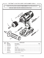
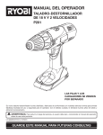
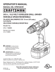
OPERATOR’S MANUAL MANUAL DEL OPERADOR 1/2 in., 19.2 VOLT 2-SPEED DRILL-DRIVER VARIABLE SPEED/REVERSIBLE TALADRO-DESTORNILLADOR DE 19,2 V 13 MM (1/2 PULG.) DOS VELOCIDADES Model No. / Número de modelo 315.DD2101 LO CK WARNING: To reduce the risk of injury, the user must read and understand the operator’s manual before using this product. ADVERTENCIA: Para reducir el riesgo de lesiones, el usuario debe leer y comprender el manual del operador antes de usar este producto. Customer Help Line: 1-800-932-3188 Teléfono de atención al consumidor: 1-800-932-3188 Sears Brands Management Corporation, 3333 Beverly Rd., Hoffman Estates, IL 60179 USA Visit the Craftsman web page: www.sears.com/craftsman Visite el sitio web de Craftsman: www.sears.com/craftsman Save this manual for future reference 990000415 2-4-13 (REV:01) Guarde este manual para futuras consulta TABLE OF CONTENTS / ÍNDICE DE CONTENIDO ENGLISH ESPAÑOL Warranty.......................................................................2 Garantía.......................................................................2 Introduction..................................................................2 Introducción.................................................................2 General Power Tool Safety Warnings...................... 3-4 Drill-Driver Safety Warnings.........................................4 Advertencias de seguridad para herramientas eléctricas.................................................................. 3-4 Symbols.......................................................................5 Advertencias de seguridad taladro-destornillador......4 Features.......................................................................6 Símbolos......................................................................5 Assembly................................................................. 6-7 Características.............................................................6 Operation................................................................. 7-9 Armado.................................................................... 6-7 Maintenance..............................................................10 Funcionamiento....................................................... 7-9 Exploded View and Parts List....................................11 Mantenimiento...........................................................10 Figure numbers (illustrations)..................................... i-ii Figura numeras (ilustraciones)................................... i-ii Parts Ordering / Service.............................. Back Page Pedidos de piezas / Servicio.................. Pág. posterior WARRANTY / GARANTÍA CRAFTSMAN® ONE YEAR LIMITED WARRANTY FOR ONE YEAR from the date of purchase, this product is warranted against any defects in material or workmanship. With proof of purchase, defective product will be replaced free of charge. For warranty coverage details to obtain free replacement, visit the web site: www.craftsman.com This warranty does not cover bits which are expendable part(s) that can wear out from normal use within the warranty period. This warranty is void if this product is ever used while providing commercial services or if rented to another person. This warranty gives you specific legal rights, and you may also have other rights which vary from state to state. Sears Brands Management Corporation, Hoffman Estates, IL 60179 *** GARANTÍA LIMITADA DE CRAFTSMAN® POR UN AÑO Este producto tiene garantía por cualquier defecto en material o mano de obra DURANTE UN AÑO desde la fecha de compra. Los productos defectuosos se remplazarán sin cargo si presenta un comprobante de pago. Si desea conocer los detalles de la cobertura de la garantía para conseguir reparaciones o recambios, visite el sitio Web: www.craftsman.com Esta garantía no cubre la brocas, que es una pieza fungible que puede desgastarse por el uso normal durante el período de garantía. La garantía pierde validez si este producto se utiliza mientras se prestan servicios comerciales o si se alquila a otra persona. Esta garantía le otorga derechos legales específicos y también puede gozar de otros derechos que varían según el estado. Sears Brands Management Corporation, Hoffman Estates, IL 60179 INTRODUCTION / INTRODUCCIÓN This tool has many features for making its use more pleasant and enjoyable. Safety, performance, and d ependability have been given top priority in the design of this product making it easy to maintain and operate. *** Esta herramienta ofrece numerosas características para hacer más agradable y placentero su uso. En el diseño de este producto se ha conferido prioridad a la seguridad, el desempeño y la fiabilidad, por lo cual se facilita su manejo y mantenimiento. 2 – English GENERAL POWER TOOL SAFETY WARNINGS WARNING Read all safety warnings and all instructions. Failure to follow the warnings and instructions may result in electric shock, fire and/or serious injury. Save all warnings and instructions for future reference. The term “power tool” in the warnings refers to your mains-operated (corded) power tool or battery-operated (cordless) power tool. WORK AREA SAFETY Keep work area clean and well lit. Cluttered or dark areas invite accidents. Do not operate power tools in explosive atmospheres, such as in the presence of flammable liquids, gases or dust. Power tools create sparks which may ignite the dust or fumes. Keep children and bystanders away while operating a power tool. Distractions can cause you to lose control. ELECTRICAL SAFETY Power tool plugs must match the outlet. Never modify the plug in any way. Do not use any adapter plugs with earthed (grounded) power tools. Unmodified plugs and matching outlets will reduce risk of electric shock. Avoid body contact with earthed or grounded surfaces such as pipes, radiators, ranges and refrigerators. There is an increased risk of electric shock if your body is earthed or grounded. Do not expose power tools to rain or wet conditions. Water entering a power tool will increase the risk of electric shock. Do not abuse the cord. Never use the cord for carrying, pulling or unplugging the power tool. Keep cord away from heat, oil, sharp edges or moving parts. Damaged or entangled cords increase the risk of electric shock. When operating a power tool outdoors, use an extension cord suitable for outdoor use. Use of a cord suitable for outdoor use reduces the risk of electric shock. If operating a power tool in a damp location is unavoidable, use a ground fault circuit interrupter (GFCI) protected supply. Use of a GFCI reduces the risk of electric shock. Use battery only with charger listed. For use with 19.2V nickel-cadmium and 19.2V lithium-ion battery packs, see tool/appliance/battery pack/charger correlation supplement 988000-272. Use personal protective equipment. Always wear eye protection. Protective equipment such as dust mask, non-skid safety shoes, hard hat, or hearing protection used for appropriate conditions will reduce personal injuries. Prevent unintentional starting. Ensure the switch is in the off-position before connecting to power source and/or battery pack, picking up or carrying the tool. Carrying power tools with your finger on the switch or energising power tools that have the switch on invites accidents. Remove any adjusting key or wrench before turning the power tool on. A wrench or a key left attached to a rotating part of the power tool may result in personal injury. Do not overreach. Keep proper footing and balance at all times. This enables better control of the power tool in unexpected situations. Dress properly. Do not wear loose clothing or jewellery. Keep your hair, clothing and gloves away from moving parts. Loose clothes, jewellery or long hair can be caught in moving parts. If devices are provided for the connection of dust extraction and collection facilities, ensure these are connected and properly used. Use of dust collection can reduce dust-related hazards. Do not wear loose clothing or jewelry. Contain long hair. Loose clothes, jewelry, or long hair can be drawn into air vents. Do not use on a ladder or unstable support. Stable footing on a solid surface enables better control of the power tool in unexpected situations. POWER TOOL USE AND CARE Do not force the power tool. Use the correct power tool for your application. The correct power tool will do the job better and safer at the rate for which it was designed. Do not use the power tool if the switch does not turn it on and off. Any power tool that cannot be controlled with the switch is dangerous and must be repaired. Disconnect the plug from the power source and/or the battery pack from the power tool before making any adjustments, changing accessories, or storing power tools. Such preventive safety measures reduce the risk of starting the power tool accidentally. Store idle power tools out of the reach of children and do not allow persons unfamiliar with the power tool or these instructions to operate the power tool. Power tools are dangerous in the hands of untrained users. PERSONAL SAFETY Maintain power tools. Check for misalignment or Stay alert, watch what you are doing and use binding of moving parts, breakage of parts and any common sense when operating a power tool. Do other condition that may affect the power tool’s not use a power tool while you are tired or under the operation.If damaged, have the power tool repaired influence of drugs, alcohol or medication. A moment before use. Many accidents are caused by poorly of inattention while operating power tools may result in maintained power tools. serious personal injury. 3 – English GENERAL POWER TOOL SAFETY WARNINGS Keep cutting tools sharp and clean. Properly maintained cutting tools with sharp cutting edges are less likely to bind and are easier to control. Use the power tool, accessories and tool bits etc. in accordance with these instructions, taking into account the working conditions and the work to be performed. Use of the power tool for operations different from those intended could result in a hazardous situation. nails, screws or other small metal objects, that can make a connection from one terminal to another. Shorting the battery terminals together may cause burns or a fire. Under abusive conditions, liquid may be ejected from the battery; avoid contact. If contact accidentally occurs, flush with water. If liquid contacts eyes, additionally seek medical help. Liquid ejected from the battery may cause irritation or burns. BATTERY TOOL USE AND CARE SERVICE Recharge only with the charger specified by the manufacturer. A charger that is suitable for one type of battery pack may create a risk of fire when used with another battery pack. Use power tools only with specifically designated battery packs. Use of any other battery packs may create a risk of injury and fire. When battery pack is not in use, keep it away from other metal objects, like paper clips, coins, keys, Have your power tool serviced by a qualified repair person using only identical replacement parts. This will ensure that the safety of the power tool is maintained. When servicing a power tool, use only identical replacement parts. Follow instructions in the Maintenance section of this manual. Use of unauthorized parts or failure to follow Maintenance instructions may create a risk of shock or injury. DRILL-DRIVER SAFETY WARNINGS Do not crush, drop or damage battery pack. Do Use auxiliary handle(s), if supplied with the tool. not use a battery pack or charger that has been Loss of control can cause personal injury. dropped or received a sharp blow. A damaged Hold power tool by insulated gripping surfaces, battery is subject to explosion. Properly dispose of a when performing an operation where the cutting dropped or damaged battery immediately. accessory may contact hidden wiring. Cutting Batteries can explode in the presence of a source accessory contacting a “live” wire may make exposed of ignition, such as a pilot light. To reduce the risk of metal parts of the power tool “live” and could give the serious personal injury, never use any cordless product operator an electric shock. in the presence of open flame. An exploded battery Know your power tool. Read operator’s manual can propel debris and chemicals. If exposed, flush with carefully. Learn its applications and limitations, as water immediately. well as the specific potential hazards related to this Do not charge battery tool in a damp or wet power tool. Following this rule will reduce the risk of location. Following this rule will reduce the risk of electric shock, fire, or serious injury. electric shock. Always wear eye protection with side shields For best results, your battery tool should be marked to comply with ANSI Z87.1 when charged in a location where the temperature is assembling parts, operating the tool, or performing more than 50°F but less than 100°F. To reduce the maintenance. Following this rule will reduce the risk of risk of serious personal injury, do not store outside or serious personal injury. in vehicles. Protect your lungs. Wear a face or dust mask if the Under extreme usage or temperature conditions, operation is dusty. Following this rule will reduce the battery leakage may occur. If liquid comes in risk of serious personal injury. contact with your skin, wash immediately with soap Protect your hearing. Wear hearing protection and water. If liquid gets into your eyes, flush them during extended periods of operation. Following this with clean water for at least 10 minutes, then seek rule will reduce the risk of serious personal injury. immediate medical attention. Following this rule will Battery tools do not have to be plugged into an reduce the risk of serious personal injury. electrical outlet; therefore, they are always in Save these instructions. Refer to them frequently operating condition. Be aware of possible hazards and use them to instruct others who may use this when not using your battery tool or when changing tool. If you loan someone this tool, loan them these accessories. Following this rule will reduce the risk of instructions also. electric shock, fire, or serious personal injury. Do not place battery tools or their batteries near fire or heat. This will reduce the risk of explosion and possibly injury. 4 – English SYMBOLS The following signal words and meanings are intended to explain the levels of risk associated with this product. SYMBOL SIGNAL MEANING DANGER: Indicates an imminently hazardous situation, which, if not avoided, will result in death or serious injury. WARNING: Indicates a potentially hazardous situation, which, if not avoided, could result in death or serious injury. CAUTION: Indicates a potentially hazardous situation, which, if not avoided, may result in minor or moderate injury. NOTICE: (Without Safety Alert Symbol) Indicates important information not related to an injury hazard, such as a situation that may result in property damage. Some of the following symbols may be used on this product. Please study them and learn their meaning. Proper interpretation of these symbols will allow you to operate the product better and safer. SYMBOL V min no .../min NAME DESIGNATION/EXPLANATION Safety Alert Indicates a potential personal injury hazard. Read Operator’s Manual To reduce the risk of injury, user must read and understand operator’s manual before using this product. Eye Protection Always wear eye protection with side shields marked to comply with ANSI Z87.1. Wet Conditions Alert Do not expose to rain or use in damp locations. Recycle Symbols This product uses nickel-cadmium (Ni-Cd) and lithium-ion (Li-ion) batteries. Local, state or federal laws may prohibit disposal of batteries in ordinary trash. Consult your local waste authority for information regarding available recycling and/or disposal options. Volts Voltage Minutes Time Direct Current Type or a characteristic of current No Load Speed Rotational speed, at no load Per Minute Revolutions, strokes, surface speed, orbits etc., per minute CALIFORNIA PROPOSITION 65 WARNING: This product and some dust created by power sanding, sawing, grinding, drilling, and other construction activities may contain chemicals, including lead, known to the State of California to cause cancer, birth defects, or other reproductive harm. Wash hands after handling. Some examples of these chemicals are: • lead from lead-based paints, • crystalline silica from bricks and cement and other masonry products and, • arsenic and chromium from chemically treated lumber. Your risk from these exposures varies, depending on how often you do this type of work. To reduce your exposure to these chemicals: work in a well ventilated area, and work with approved safety equipment, such as those dust masks that are specially designed to filter out microscopic particles. 5 – English FEATURES PRODUCT SPECIFICATIONS Chuck............................................................1/2 in. Keyless Motor................................................................ 19.2 Volt DC Switch............................... VSR (Variable Speed Reversible) No Load Speed........................ 0-375/0-1,600 r/min. (RPM) Clutch............................................................... 24 Positions Torque.................................................................... 465 in.lb. KNOW YOUR DRILL-DRIVER LED WORKLIGHT See Figure 1, page i. The safe use of this product requires an understanding of the information on the tool and in this operator’s manual as well as a knowledge of the project you are attempting. Before use of this product, familiarize yourself with all operating features and safety rules. AUXILIARY HANDLE Your drill is equipped with an auxiliary handle for ease of operation and to prevent loss of control. BIT STORAGE Bits provided with the drill-driver can be placed in the storage area, located on the base of the tool. DIRECTION OF ROTATION SELECTOR (FORWARD/REVERSE/CENTER LOCK) Your drill-driver has a direction of rotation (forward/ reverse/center lock) selector located above the switch trigger for changing the direction of bit rotation. Setting the direction of rotation selector in the OFF (center lock) position will lock the switch trigger to help reduce the possibility of accidental starting when not in use. The LED worklight illuminates when the switch trigger is depressed. This provides extra light for increased visibility. KEYLESS CHUCK The keyless chuck allows you to hand-tighten or release the drill bit in the chuck jaws. LEVEL A level is located on the rear of the motor housing to help keep the drill bit level during use. TORQUE ADJUSTMENT RING Your drill has a 24-position clutch. The torque adjustment ring can be turned to select the right amount of torque for your application. TWO-SPEED GEAR TRAIN (HI-LO) The two-speed gear train is designed for drilling or driving at LO (1) or HI (2) speeds. A slide switch is located on top of your drill for selecting either LO (1) or HI (2) speed. VARIABLE SPEED The variable speed switch trigger delivers higher speed with increased trigger pressure and lower speed with decreased trigger pressure. ASSEMBLY UNPACKING PACKING LIST This product requires assembly Drill-Driver n Carefully remove the tool and any accessories from the box. Make sure that all items listed in the packing list are included. Auxiliary Handle Assembly WARNING: Do not use this product if any parts on the Packing List are already assembled to your product when you unpack it. Parts on this list are not assembled to the product by the manufacturer and require customer installation. Use of a product that may have been improperly assembled could result in serious personal injury. Double-ended Bit (2) Operator’s Manual WARNING: If any parts are damaged or missing do not operate this product until the parts are replaced. Use of this product with damaged or missing parts could result in serious personal injury. WARNING: Do not attempt to modify this tool or create accessories not recommended for use n Inspect the tool carefully to make sure no breakage or with this tool. Any such alteration or modification is damage occurred during shipping. misuse and could result in a hazardous condition n Do not discard the packing material until you have leading to possible serious personal injury. carefully inspected and satisfactorily operated the tool. n If any parts are damaged or missing, please call 1-800-932-3188 for assistance. 6 – English ASSEMBLY WARNING: To prevent accidental starting that could cause serious personal injury, always remove the battery pack from the product when assembling parts. n Slide handle collar onto screw, seat hex end of collar into hex hole. n Thread auxiliary handle onto screw and secure tightly. WARNING: Always use the auxiliary handle when AUXILIARY HANDLE ASSEMBLY using this tool to help resist torque reactions. Binding or stalling of this product could lead to serious personal injury. See Figure 2, page i. An auxiliary handle is packed with the drill for ease of operation and to help prevent loss of control. The handle can be mounted on either side for left or right hand use. n Insert handle screw into hole located above trigger switch and seat hex head into hole. OPERATION C3 ENERGY INDICATOR WINDOW WARNING: Do not allow familiarity with tools See Figure 3, page i. to make you careless. Remember that a careless fraction of a second is sufficient to inflict serious injury. WARNING: Always wear eye protection with side shields marked to comply with ANSI Z87.1. Failure to do so could result in objects being thrown into your eyes resulting in possible serious injury. The C3 energy indicator window located on the side of the handle, just above the base, will light when some Craftsman® 19.2 V lithium-ion battery packs are installed and have charge (315.113710, 315.PP2000, 315.PP2010, 315.PP2020, 315.PP2030). NOTE: Feature will not light with Craftsman® 19.2 V nickel-cadmium battery packs. INSTALLING/REMOVING BATTERY PACK WARNING: Do not use any attachments or accessories not recommended by the manufacturer of this tool. The use of attachments or accessories not recommended can result in serious personal injury. APPLICATIONS You may use this product for the purposes listed below: Drilling in all types of wood products (lumber, plywood, paneling, composition board, and hard board) See Figure 3, page i. To install: Lock the switch trigger by placing the direction of rotation selector in the center position. Place battery pack in the tool. Align raised rib on battery pack with groove inside tool. Make sure the latches on each side of the battery pack snap into place and battery pack is secured in tool before beginning operation. Drilling in ceramics, plastics, fiberglass, and laminates WARNING: Always remove battery pack from Drilling in metals your tool when you are assembling parts, making adjustments, cleaning, or when not in use. Removing battery pack will prevent accidental starting that could cause serious personal injury. Driving screws into wood and drywall with screwdriver bits This product will accept Craftsman® 19.2 V lithium-ion battery packs and Craftsman® 19.2 V nickel-cadmium battery packs. For complete charging instructions, refer to the Operator’s Manual for your battery pack and charger models. To remove: Lock the switch trigger by placing the direction of rotation selector in the center position. Locate latches on end of battery pack and depress to release battery pack from the tool. Remove battery pack. WARNING: Battery products are always in operating condition. Therefore, the switch should always be locked when not in use or carrying at your side. 7 – English OPERATION SWITCH TRIGGER TWO-SPEED GEAR TRAIN (HI-LO) See Figure 4, page i. See Figure 6, page i. To turn the drill ON, depress the switch trigger. To turn it OFF, release the switch trigger. VARIABLE SPEED The variable speed switch trigger delivers higher speed with increased trigger pressure and lower speed with decreased trigger pressure. NOTE: You might hear a whistling or ringing noise from the switch during use. Do not be concerned; this is a normal part of the switch function. The drill has a two-speed gear train designed for drilling or driving at LO (1) or HI (2) speeds. A slide switch is located on top of the drill to select either LO (1) or HI (2) speed. When using drill in the LO (1) speed range, speed will decrease and unit will have more torque. When using drill in the HI (2) speed range, speed will increase and unit will have less torque. Use LO (1) speed for high torque applications and HI (2) speed for fast drilling or driving applications. NOTICE: Never change speeds while the tool is DIRECTION OF ROTATION SELECTOR running. Failure to obey this caution could result in serious damage to the drill. (FORWARD/REVERSE/CENTER LOCK) See Figure 4, page i. The direction of bit rotation is reversible and is controlled by a selector located above the switch trigger. With the drill held in normal operating position, the direction of rotation selector should be positioned to the left of the switch trigger for forward drilling. The drilling direction is reversed when the selector is to the right of the switch trigger. Setting the direction of rotation selector in the OFF (center lock) position helps reduce the possibility of accidental starting when not in use. NOTICE: To prevent gear damage, always allow the chuck to come to a complete stop before changing the direction of rotation. To stop the drill, release the switch trigger and allow the chuck to come to a complete stop. NOTE: The drill will not run unless the direction of rotation selector is pushed fully to the left or right. Avoid running the drill at low speeds for extended periods of time. Running at low speeds under constant usage may cause the drill to become overheated. If this occurs, cool the drill by running it without a load and at full speed. ADJUSTABLE TORQUE CLUTCH This product is equipped with an adjustable torque clutch for driving different types of screws into different materials. The proper setting depends on the type of material and the size of screw you are using. ADJUSTING TORQUE See Figure 7, page ii. There are twenty-four torque indicator settings located on the front of the drill. Rotate the adjusting ring to the desired setting. • 1 - 4 For driving small screws • 5 - 8 For driving screws into soft material • 9 - 12 For driving screws into soft and hard materials • 13 - 16 For driving screws into hard wood • 17 - 20 For driving large screws •21- For heavy drilling INSTALLING/REMOVING BITS See Figures 8 - 10, page ii. KEYLESS CHUCK To install: See Figure 5, page i. The drill has a keyless chuck to tighten or release drill bits in the chuck jaws. The arrows on the chuck indicate which direction to rotate the chuck body in order to LOCK (tighten) or UNLOCK (release) the drill bit. Lock the switch trigger by placing the direction of rotation selector in the center position. WARNING: Do not hold the chuck with one hand and use the power of the drill to tighten the chuck jaws on the drill bit. The chuck body could slip in your hand, or your hand could slip and come in contact with the rotating drill bit. This could cause an accident resulting in serious personal injury. Open or close the chuck jaws to a point where the opening is slightly larger than the bit size you intend to use. Also, raise the front of the drill slightly to keep the bit from falling out of the chuck jaws. Insert the bit. 8 – English WARNING: Make sure to insert the bit straight into the chuck jaws. Do not insert the bit into the chuck jaws at an angle then tighten, as shown in figure 9. This could cause the bit to be thrown from the drill, resulting in possible serious personal injury or damage to the chuck. OPERATION Tighten the chuck jaws securely on the bit. WARNING: When drilling, be prepared for binding NOTE: Rotate the chuck body in the direction of the arrow marked LOCK to close the chuck jaws. Do not use a wrench to tighten or loosen the chuck jaws. at bit breakthrough. When these situations occur, drill has a tendency to grab and kick opposite to the direction of rotation and could cause loss of control when breaking through material. If not prepared, this loss of control can result in possible serious injury. To remove: Lock the switch trigger by placing the direction of rotation selector in the center position. Open the chuck jaws. NOTE: Rotate the chuck body in the direction of the arrow marked UNLOCK to open the chuck jaws. Do not use a wrench to tighten or loosen the chuck jaws. Remove the bit. Bits can be placed in the storage area, located on the base of the drill. DRILLING/DRIVING SCREWS See Figure 11, page ii. A level is located on the top of the motor housing to help keep the drill bit level during use. Check the direction of rotation selector for the correct setting (forward or reverse). Use LO (1) speed for high torque applications and HI (2) speed for fast drilling or driving applications. Refer to Two-Speed Gear Train and Adjusting Torque. Secure the workpiece in a vise or with clamps to keep it from turning as the bit rotates. Install auxiliary handle. Hold the drill firmly and place the bit at the point to be drilled, or where the screw is to be driven. WARNING: Do not drive a screw where there is likely to be hidden wiring behind the surface. Contact with a “live” wire will make exposed metal parts of the tool “live” and possibly shock the operator. If you must drive a screw where hidden wire may be present, always hold tool by insulated gripping surfaces (handle) when performing the operation to prevent a shock to the operator. Depress the switch trigger to start the drill. Move the bit into the workpiece, applying only enough pressure to keep the bit cutting. Do not force the drill or apply side pressure to elongate a hole. Let the tool do the work. With hard, smooth surfaces, use a center punch to mark the desired hole location. This will prevent the bit from slipping off-center as the hole is started. If the bit jams in the workpiece or if the drill stalls, stop the tool immediately. Remove the bit from the workpiece and determine the reason for jamming. NOTE: This drill has an electric brake. When the switch trigger is released, the chuck stops turning. When the brake is functioning properly, sparks will be visible through the vent slots on the housing. This is normal and is the action of the brake. WOOD AND METAL DRILLING For maximum performance, use high speed steel bits for wood or metal drilling. Begin drilling at a very low speed to prevent the bit from slipping off the starting point. Wood Drilling Increase the speed as the drill bit bites into the material. When drilling through holes, place a block of wood behind the workpiece to prevent ragged or splintered edges on the back side of the hole. Metal and Steel Drilling Use a light oil on the drill bit to keep it from overheating. The oil will prolong the life of the bit and increase the drilling action. Maintain a speed and pressure which allows cutting without overheating the bit. Applying too much pressure will: • Overheat the drill; • Wear the bearings; • Bend or burn bits; and • Produce off-center or irregular-shaped holes. When drilling large holes in metal, start with a small bit, then finish with a larger bit. 9 – English MAINTENANCE CHUCK REMOVAL WARNING: When servicing, use only identical Craftsman replacement parts. Use of any other part can create a hazard or cause product damage. WARNING: Always wear eye protection with side shields marked to comply with ANSI Z87.1. Failure to do so could result in objects being thrown into your eyes resulting in possible serious injury. WARNING: To avoid serious personal injury, always remove the battery pack from the tool when cleaning, performing any maintenance, or when storing the tool. GENERAL MAINTENANCE Avoid using solvents when cleaning plastic parts. Most plastics are susceptible to damage from various types of commercial solvents and may be damaged by their use. Use clean cloths to remove dirt, dust, oil, grease, etc. WARNING: Do not at any time let brake fluids, gasoline, petroleum-based products, penetrating oils, etc., come in contact with plastic parts. Chemicals can damage, weaken or destroy plastic which could result in serious personal injury. Only the parts shown on the parts list are intended to be repaired or replaced by the customer. All other parts should be replaced at a Sears Service Center. BATTERY PACK REMOVAL AND PREPARATION FOR RECYCLING WARNING: Upon removal, cover the battery pack’s terminals with heavy-duty adhesive tape. Do not attempt to destroy or disassemble battery pack or remove any of its components. Batteries must be recycled or disposed of properly. Also, never touch both terminals with metal objects and/or body parts as short circuit may result. Keep away from children. Failure to comply with these warnings could result in fire and/or serious injury. See Figures 12 - 14, page ii. The chuck may be removed and replaced by a new one. Lock the switch trigger by placing the direction of rotation selector in center position. Insert a 5/16 in. or larger hex key into the chuck of the drill and tighten the chuck jaws securely. Tap the hex key sharply with a mallet in a clockwise direction. This will loosen the screw in the chuck for easy removal. Open the chuck jaws and remove the hex key. Using a screwdriver, remove the chuck screw by turning it in a clockwise direction. NOTE: The chuck screw has left hand threads. Insert the hex key into the chuck and tighten the chuck jaws securely. Tap sharply with a mallet in a counterclockwise direction. This will loosen the chuck on the spindle. It can now be unscrewed by hand. TO RETIGHTEN A LOOSE CHUCK The chuck may become loose on the spindle and develop a wobble. Also, the chuck screw may become loose, causing the chuck jaws to bind and prevent them from closing. To tighten: Lock the switch trigger by placing the direction of rotation selector in the center position. Open the chuck jaws. Insert the hex key into the chuck and tighten the chuck jaws securely. Tap the hex key sharply with a mallet in a clockwise direction. This will tighten the chuck on the spindle. Open the chuck jaws and remove the hex key. Using a screwdriver, tighten the chuck screw by turning in a counterclockwise direction. 10 – English CRAFTSMAN® 19.2 VOLT DRILL-DRIVER – MODEL NUMBER 315.DD2101 The model number will be found on a label attached to the motor housing. Always mention the model number in all correspondence regarding your DRILL-DRIVER or when ordering repair parts. SEE BACK PAGE FOR PARTS ORDERING INSTRUCTIONS 4 2 3 LO CK 1 5 6 7 Key Part PARTS LIST No. NumberDescription 1 2 3 4 5 6 7 660134006 670794005 941003161 941002030 6782405 6782106 305560003 990000415 Qty. Screw (Special).................................................................................................1 Chuck...............................................................................................................1 Data Label........................................................................................................1 Logo Label.......................................................................................................1 Double-ended Bit, Flat Head...........................................................................1 Double-ended Bit, Phillips Head......................................................................1 Auxiliary Handle Assembly...............................................................................1 Operator’s Manual 11 – English Fig. 1 Fig. 4 B A B A CK LO C D LO CK L N C E I K F D A-Direction of rotation selector (forward/ reverse/center lock) [selector de sentido de giro (adelante/atrás/seguro en el centro)] B-Reverse (marcha atrás) C-Forward (marcha adelante) D-Variable speed switch trigger (gatillo del interruptor de velocidad variable) Fig. 5 M J A CK LO B I Fig. 2 H-C3 energy indicator button (botón del indicador de energía C3) I -Bit storage (compartimiento de puntas de destornillador) J-Screwdriver bit (punta de destornillador) K-C3 energy indicator window (visor del indicador de energía C3) L-Direction of rotation selector (forward/ reverse/center lock) [selector de sentido de giro (adelante/atrás/seguro en el centro)] M-Battery pack (paquete de batería) N-Auxiliary handle (mango auxiliar) K H A-Level (nivel) B-Two-speed gear train (hi-lo) [engranaje de dos velocidades (alta-baja)] C-Torque adjustment ring (anillo de ajuste de fuerza de torsión) D-Keyless chuck (portabrocas de apriete sin llave) E-Switch trigger (gatillo del interruptor) F-LED worklight (luz de trabajo con diodo luminiscente) G- C3 energy indicator light (luz del indicador de energía C3) LOC G C D A-Unlock (release) [unlock (aflojar)] B-Chuck Jaws (mordazas del portabrocas) C-Lock (tighten) [lock (apretar)] D-Keyless chuck (portabrocas de apriete sin llave) Fig. 6 A C Fig. 3 D B C LO CK LOCK D A B C B C A A-Handle screw (tornillo del mango) B-Hex head hole (orificio de la cabeza hexagonal) C-Handle collar (collar del mango) D-Auxiliary handle (mango auxiliar) A-Battery pack (paquete de batería) B-Latches (pestillos) C-Depress latches to release battery pack (para soltar el paquete de batería oprima los pestillos) D-C3 energy indicator window (visor del indicador de energía C3) i A-Two-speed gear train (hi-lo) [engranaje de dos velocidades (alta-baja)] B-HI speed (velocidad alta) C-LO speed (velocidad baja) LO CK Fig. 7 A C Fig. 10 Fig. 13 A LO CK A K LOC B A B B A-To decrease torque (para disminuir la fuerza de torsión) B-To increase torque (para aumentar la fuerza de torsión) C-Adjusting ring (anillo de ajuste) A-Screwdriver bit (punta de destornillador) B-Bit storage (compartimiento de puntas de destornillador) Fig. 11 A-Screwdriver (destornillador) Fig. 14 A Fig. 8 A A D F LOCK LO CK C B E B A-Mallet (mazo de goma) B-Hex key (llave hexagonal) B RIGHT FORMA CORRECTA A-Drill bit (broca) B-Keyless chuck (portabrocas de apriete sin llave) C-Chuck Jaws (mordazas del portabrocas) D-Unlock (release) [unlock (aflojar)] E-Lock (tighten) [lock (apretar)] F-Chuck body (cuerpo del portabrocas) A-Level (nivel) B-LED worklight (luz de trabajo con diodo luminiscente) Fig. 12 A Fig. 9 B LO CK LOCK LO CK D C WRONG FORMA INCORRECTA A-Mallet (mazo de goma) B-Chuck jaws (mordazas del portabrocas) C-Hex key (llave hexagonal) D-Keyless chuck (portabrocas de apriete sin llave) ii ADVERTENCIAS DE SEGURIDAD PARA HERRAMIENTAS ELÉCTRICAS ADVERTENCIA Lea todas las advertencias de seguridad y las instrucciones. El incumplimiento de las advertencias e instrucciones puede ocasionar descarga eléctrica, fuego o lesiones graves. Guarde todas las advertencias e instrucciones para futuras consultas. El término “herramienta eléctrica” empleado en todos los avisos de advertencia enumerados abajo se refiere a las herramientas eléctricas de cordón (alámbricas) y de baterías (inalámbricas). SEGURIDAD EN EL ÁREA DE TRABAJO Mantenga limpia y bien iluminada el área de trabajo. Un área de trabajo mal despejada o mal iluminada propicia accidentes. No utilice herramientas motorizadas en atmósferas explosivas, como las existentes alrededor de líquidos, gases y polvos inflamables. Las herramientas eléctricas generan chispas que pueden encender el polvo y los vapores inflamables. Mantenga alejados a los niños y circunstantes al maniobrar una herramienta eléctrica. Toda distracción puede causar pérdida del control de la herramienta. SEGURIDAD ELÉCTRICA Las clavijas de las herramientas eléctricas deben corresponder a las tomas de corriente donde se conectan. Nunca modifique la clavija de ninguna forma. No utilice ninguna clavija adaptadora con herramientas eléctricas dotadas de contacto a tierra. Conectando las clavijas originales en las tomas de corriente donde corresponden se disminuye el riesgo de una descarga eléctrica. Evite el contacto del cuerpo con las superficies de objetos que estén haciendo tierra o estén conectados a ésta, como tuberías, radiadores, estufas y refrigeradores. Existe un mayor riesgo de descargas eléctricas si el cuerpo está haciendo tierra. No exponga las herramientas eléctricas a la lluvia ni a condiciones de humedad. La introducción de agua en una herramienta eléctrica aumenta el riesgo de descargas eléctricas. No maltrate el cordón eléctrico. Nunca utilice el cordón para trasladar, desconectar o tirar de la herramienta eléctrica. Mantenga el cordón alejado del calor, del aceite, de bordes afilados y de piezas móviles. Los cordones eléctricos dañados o enredados aumentan el riesgo de descargas eléctricas. Al utilizar una herramienta eléctrica a la intemperie, use un cordón de extensión apropiado para el exterior. Usando un cordón adecuado para el exterior se disminuye el riesgo de descargas eléctricas. Si inevitablemente debe utilizar una herramienta eléctrica en un lugar húmedo, utilice un interruptor de circuito con pérdida a tierra (GFCI) para tener un suministro protegido. El uso de un GFCI disminuye el riesgo de descarga eléctrica. Cargue las baterías solamente con el cargador indicado. Para utilizar con paquetes de baterías de níquel-cadmio de 19,2 V o de iones de litio de 19,2 V, consulte el folleto de la herramienta/aparato/paquete de baterías/cargador complementario 988000-272. SEGURIDAD PERSONAL Permanezca alerta, preste atención a lo que esté haciendo y aplique el sentido común al utilizar herramientas eléctricas. No utilice la herramienta eléctrica si está cansado o se encuentra bajo los efectos de alguna droga, alcohol o medicamento. Un momento de inatención al utilizar una herramienta eléctrica puede causar lesiones corporales serias. Use equipo de seguridad. Siempre póngase protección ocular. El uso de equipo de seguridad como mascarilla para el polvo, calzado de seguridad, casco y protección para los oídos en las circunstancias donde corresponda disminuye el riesgo de lesiones. Evite un arranque accidental de la unidad. Asegúrese de que el interruptor esté en la posición de apagado antes de conectar la herramienta. Portar las herramientas eléctricas con el dedo en el interruptor, o conectarlas con el interruptor puesto, propicia accidentes. Retire toda llave o herramienta de ajuste antes de encender la herramienta eléctrica. Toda llave o herramienta de ajuste dejada en una pieza giratoria de la herramienta eléctrica puede causar lesiones. No estire el cuerpo para alcanzar mayor distancia. Mantenga una postura firme y buen equilibrio en todo momento. De esta manera se logra un mejor control de la herramienta eléctrica en situaciones inesperadas. Vístase adecuadamente. No vista ropas holgadas ni joyas. Mantenga el cabello, la ropa y los guantes alejados de las piezas móviles. Las ropas holgadas, las joyas y el cabello largo pueden engancharse en las piezas móviles. Si se suministran dispositivos para conectar mangueras de extracción y captación de polvo, asegúrese de que éstas estén bien conectadas y se usen correctamente. La utilización de captador de polvo puede disminuir los peligros relacionados con el polvo. No vista ropas holgadas ni joyas. Recójase el cabello si está largo. Las ropas holgadas y las joyas, así como el cabello largo, pueden resultar atraídas hacia el interior de las aberturas de ventilación. No utilice la unidad al estar en una escalera o en un soporte inestable. Una postura estable sobre una superficie sólida permite un mejor control de la herramienta eléctrica en situaciones inesperadas. EMPLEO Y CUIDADO DE LA HERRAMIENTA ELÉCTRICA No fuerce la herramienta eléctrica. Utilice la herramienta eléctrica adecuada para cada trabajo. La herramienta eléctrica adecuada efectúa mejor y de manera más segura el trabajo, si además se maneja a la velocidad para la que está diseñada. No utilice la herramienta si el interruptor no enciende o no apaga. Cualquier herramienta eléctrica que no pueda controlarse con el interruptor es peligrosa y debe repararse. Desconecte la clavija del suministro de corriente o retire el paquete de baterías de la herramienta eléctrica, según sea el caso, antes de efectuarle cualquier ajuste, cambiarle accesorios o guardarla. Tales medidas preventivas de seguridad reducen el riesgo de poner en marcha accidentalmente la herramienta. Guarde las herramientas eléctricas desocupadas fuera del alcance de los niños y no permita que las utilicen personas no familiarizadas con las mismas o con estas instrucciones. Las herramientas eléctricas son peligrosas en manos de personas no capacitadas en el uso de las mismas. Preste servicio a las herramientas eléctricas. Revise para ver si hay desalineación o atoramiento de piezas móviles, ruptura de piezas o cualquier otra condición que pueda afectar el funcionamiento de la herramienta. Si está dañada la herramienta eléctrica, permita que la reparen antes de usarla. Numerosos accidentes son causados por herramientas eléctricas mal cuidadas. 3 - Español ADVERTENCIAS DE SEGURIDAD PARA HERRAMIENTAS ELÉCTRICAS Mantenga las herramientas de corte afiladas y limpias. Las herramientas de corte bien cuidadas y con bordes bien afilados, tienen menos probabilidad de atascarse en la pieza de trabajo y son más fáciles de controlar. Utilice la herramienta eléctrica, los accesorios y brocas, hojas y cuchillas de corte, ruedas de esmeril, etc. de conformidad con estas instrucciones, tomando en cuenta las condiciones de trabajo y la tarea por realizar. Si se utiliza la herramienta eléctrica para operaciones diferentes de las indicadas podría originar una situación peligrosa. clips, monedas, llaves, clavos, tornillos o otros objetos metálicos, pequeños que puedan establecer conexión entre ambas terminales. Establecer una conexión directa entre las dos terminales de las baterías puede causar quemaduras o incendios. Si se maltratan las baterías, puede derramarse líquido de las mismas; evite todo contacto con éste. En caso de contacto, lávese con agua. Si el líquido llega a tocar los ojos, además busque atención médica. El líquido de las baterías puede causar irritación y quemaduras. EMPLEO Y CUIDADO DE LA HERRAMIENTA DE BATERÍAS SERVICIO Sólo cargue el paquete de baterías con el cargador especificado por el fabricante. Un cargador adecuado para un tipo paquete de baterías puede significar un riesgo de incendio si se emplea con un paquete de baterías diferente. Utilice las herramientas eléctricas sólo con los paquetes de baterías específicamente indicados. El empleo de paquetes de baterías diferentes puede presentar un riesgo de incendio. Cuando no esté utilizándose el paquete de baterías, manténgalo lejos de otros objetos metálicos, como Permita que un técnico de reparación calificado preste servicio a la herramienta eléctrica, y sólo con piezas de repuesto idénticas. De esta manera se mantiene la seguridad de la herramienta eléctrica. Al dar servicio a una herramienta eléctrica, sólo utilice piezas de repuesto idénticas. Siga las instrucciones señaladas en la sección Mantenimiento de este manual. El empleo de piezas no autorizadas o el incumplimiento de las instrucciones de mantenimiento puede significar un riesgo de descarga eléctrica o de lesiones.e blessures. ADVERTENCIAS DE SEGURIDAD DE TALADRO-DESTORNILLADOR Utilice el o los mangos auxiliares, de venir provistos junto con la herramienta. Cualquier pérdida de control puede causar lesiones personales. Sujete las herramientas eléctricas por las superficies aisladas de sujeción al efectuar una operación en la cual la herramienta de corte pueda entrar en contacto con cables ocultos o con su propio cordón eléctrico. Todo contacto de una herramienta con un cable cargado carga las piezas metálicas expuestas de la herramienta y da una descarga eléctrica al operador. Familiarícese con su herramienta eléctrica. Lea cuidadosamente el manual del operador. Aprenda sus usos y limitaciones, así como los posibles peligros específicos de esta herramienta eléctrica. Con el cumplimiento de esta regla se reduce el riesgo de una descarga eléctrica, incendio o lesión seria. Siempre póngase protección ocular con protección lateral con la marca de cumplimiento de la norma ANSI Z87.1. Con el cumplimiento de esta regla se reduce el riesgo de lesiones serias. Protéjase los pulmones. Use una careta o mascarilla contra el polvo si la operación genera mucho polvo. Con el cumplimiento de esta regla se reduce el riesgo de lesiones serias. Protéjase los oídos. Durante períodos prolongados de utilización del producto, póngase protección para los oídos. Con el cumplimiento de esta regla se reduce el riesgo de lesiones corporales serias. No se necesita conectar a una toma de corriente las herramientas de baterías; por lo tanto, siempre están en condiciones de funcionamiento. Esté consciente de los posibles peligros cuando no esté usando la herramienta de baterías o cuando esté cambiando los accesorios de la misma. Con el cumplimiento de esta regla se reduce el riesgo de una descarga eléctrica, incendio o lesión corporal seria. No coloque herramientas de baterías ni las baterías mismas cerca del fuego o del calor. De esta manera se reduce el riesgo de explosiones y de lesiones. No aplaste, deje caer o dañe la batería. Nunca utilice una batería o cargador que se ha caído, aplastado, recibido un golpe contundente o ha sido dañado(a) de alguna manera. Las baterías dañadas pueden sufrir explosiones. Deseche de inmediato toda batería que haya sufrido una caída o cualquier daño. Las baterías pueden explotar en presencia de una fuente de inflamación, como una luz guía. Para reducir el riesgo de lesiones corporales serias, nunca use un producto inalámbrico en presencia de llamas expuestas. La explosión de una batería puede lanzar fragmentos y compuestos químicos. Si ha quedado expuesto a la explosión de una batería, lávese de inmediato con agua. No cargue herramientas de baterías en lugares mojados o húmedos. Con el cumplimiento de esta regla se reduce el riesgo de una descarga eléctrica. Para obtener resultados óptimos, debe cargar la herramienta de baterías en un lugar donde la temperatura esté entre 10 y 38 °C (entre 50 y 100 °F). Para reducir el riesgo de lesiones serias, no guarde la herramienta a la intemperie ni en el interior de vehículos. En condiciones extremas de uso o temperatura las baterías pueden emanar líquido. Si el líquido llega a tocarle la piel, lávese de inmediato con agua y jabón. Si le entra líquido en los ojos, láveselos con agua limpia por lo menos 10 minutos, y después busque de inmediato atención médica. Con el cumplimiento de esta regla se reduce el riesgo de lesiones corporales serias. Guarde estas instrucciones. Consúltelas con frecuencia y empléelas para instruir a otras personas que puedan utilizar esta herramienta. Si presta a alguien esta herramienta, facilítele también las instrucciones. 4 - Español SÍMBOLOS Las siguientes palabras de señalización y sus significados tienen el objeto de explicar los niveles de riesgo relacionados con este producto. SÍMBOLO SEÑAL SIGNIFICADO PELIGRO: Indica una situación peligrosa inminente, la cual, si no se evita, causará la muerte o lesiones serias. ADVERTENCIA: Indica una situación peligrosa posible, la cual, si no se evita, podría causar la muerte o lesiones serias. PRECAUCIÓN: Indica una situación potencialmente peligrosa la cual, si no se evita, puede causar lesiones leves o moderadas. AVISO: (Sin el símbolo de alerta de seguridad) Indica información importante no relacionada con ningún peligro de lesiones, como una situación que puede ocasionar daños físicos. Es posible que se empleen en este producto algunos de los siguientes símbolos. Le suplicamos estudiarlos y aprender su significado. Una correcta interpretación de estos símbolos le permitirá utilizar mejor y de manera más segura el producto. SÍMBOLO NOMBRE Alerta de seguridad Indica un peligro posible de lesiones personales. Lea el manual del operador Para reducir el riesgo de lesiones, el usuario debe leer y comprender el manual del operador antes de usar este producto. Protección ocular Siempre póngase protección ocular con protección lateral con la marca de cumplimiento de la norma ANSI Z87.1. Alerta de condiciones húmedas No exponga la unidad a la lluvia ni la use en lugares húmedos. Símbolos de reciclado V min no .../min DENOMINACIÓN/EXPLICACIÓN Este producto contiene baterías de níquel-cadmio (Ni-Cd) o iones de litio (Li-ion). Es posible que algunas leyes municipales, estatales o federales prohíban desechar las baterías de níquel-cadmio en la basura normal. Consulte a las autoridades reguladoras de desechos para obtener información en relación con las alternativas de reciclado y desecho disponibles. Volts Voltaje Minutos Tiempo Corriente continua Tipo o característica de corriente Velocidad en vacío Velocidad de rotación, en vacío Por minuto Revoluciones, carreras, velocidad superficial, órbitas, etc.,por minuto CALIFORNIA - PROPUESTA DE LEY NÚM. 65 ADVERTENCIA: Este producto y algunos polvos generados al efectuarse operaciones de lijado, aserrado, esmerilado, taladrado y otras actividades de la construcción, contienen sustancias químicas reconocidas por el estado de California como causantes de cáncer, defectos congénitos y otras afecciones del aparato reproductor. Lávese las manos después de utilizar el aparato. Algunos ejemplos de estas sustancias químicas son: • plomo de las pinturas a base de plomo, • sílice cristalino de los ladrillos, del cemento y de otros productos de albañilería, y • arsénico y cromo de la madera químicamente tratada. El riesgo de la exposición a estos compuestos varía, según la frecuencia con que se realice este tipo de trabajo. Para reducir la exposición personal, trabaje en áreas bien ventiladas, y con equipo de seguridad aprobado, tal como las caretas para el polvo especialmente diseñadas para filtrar partículas microscópicas. 5 - Español CARACTERÍSTICAS ESPECIFICACIONES DEL PRODUCTO Portabrocas........................ 13 mm (1/2 pulg.), de apriete sin llave Velocidad en vacío..................................0-375 / 0-1 600 rev./min. Motor...................................................................19,2 V, corr. cont. Embrague................................................................. 24 posiciones Interruptor........................... VSR (reversible de velocidad variable) Fuerza de torsión ..................................... 52,54 Nm (465 lb. pulg.) FAMILIARÍCESE CON EL TALADRODESTORNILLADOR LUZ DE TRABAJO DE DIODO LUMINISCENTE Vea la figura 1, página i. Para usar este producto con la debida seguridad se debe comprender la información indicada en la herramienta misma y en este manual, y se debe comprender también el trabajo que intenta realizar. Antes de usar este producto, familiarícese con todas las características de funcionamiento y normas de seguridad del mismo. La lámpara de trabajo de diodo luminiscente, la cual está situada debajo del portabrocas, se enciende al oprimirse el gatillo del interruptor. De esta manera se suministra luz adicional para mayor visibilidad. PORTABROCAS DE APRIETE SIN LLAVE El portabrocas de apriete sin llave permite apretar o aflojar a mano la broca en las mordazas del portabrocas. MANGO AUXILIAR NIVEL El taladro está equipado de un mango auxiliar para facilitar su manejo y evitar la pérdida de control. Hay un nivel ubicado en la parte superior del alojamiento del motor para mantener nivelada la broca durante el uso de la herramienta. LUGAR PARA GUARDAR PUNTA Las puntas de destornillador suministradas con el taladrodestornillador pueden colocarse en el compartimiento situado en la base de la unidad. SELECTOR DE SENTIDO DE ROTACIÓN (MARCHA ADELANTE, ATRÁS, SEGURO EN EL CENTRO) El taladro está provisto de un selector de sentido de giro (marcha adelante, atrás, seguro en el centro), situado arriba del gatillo del interruptor, que permite cambiar la dirección en que gira la broca. Ajustar el selector de dirección de giro en la posición de APAGADO (seguro central) asegurará el gatillo del interruptor para ayudar a reducir el riesgo de arranque accidental cuando no se utiliza la unidad. ANILLO DE AJUSTE DE FUERZA DE TORSIÓN El taladro incorpora un embrague de 24 posiciones. El anillo de ajuste de la fuerza de torsión puede girarse para escoger la cantidad correcta de torsión necesaria en cada caso. ENGRANAJE DE DOS VELOCIDADES (ALTA-BAJA) El engranaje de dos velocidades taladra o atornilla a velocidad BAJA, posición (1) o ALTA, posición (2). Hay un interruptor deslizante en la parte superior del taladro para seleccionar velocidad BAJA, posición (1), o ALTA, posición (2). VELOCIDAD VARIABLE El gatillo del interruptor produce mayor velocidad cuanta mayor presión se aplica en el gatillo, y menor velocidad cuanta menor presión se aplica en el mismo. ARMADO DESEMPAQUETADO LISTA DE EMPAQUETADO Este producto se empaca completamente armado. Taladro-destornillador n Extraiga cuidadosamente de la caja la herramienta y los accesorios. Compruebe que estén presentes todos los artículos enumerados en la lista de empaquetado. Conjunto de mango auxiliar Punta de destornillador dobles (2) Manual del operador ADVERTENCIA: No use este producto si no está totalmente ensamblado o si alguna pieza falta o está dañada. Si utiliza un producto que no se encuentra ensamblado de forma correcta y completa, puede sufrir lesiones graves. n Inspeccione cuidadosamente la herramienta, para verificar que no haya sufrido ninguna rotura o daño durante el transporte. n No deseche el material de empaquetado hasta que haya inspeccionado la herramienta con cuidado y la haya utilizado satisfactoriamente. n Si hay piezas dañadas o faltantes, sírvase llamar al 1-800-932-3188, donde le brindaremos la asistencia necesaria. 6 - Español ADVERTENCIA: Si hay piezas dañadas o faltantes, no utilice esta herramienta sin haber reemplazado las piezas dañadas o faltantes. Usar este producto con falta o está dañada alguna pieza podría tener como resultado herida personal grave. ADVERTENCIA: No intente modificar esta herramienta ni fabricar accesorios no recomendados para ella. Cualquier alteración o modificación constituye maltrato y puede causar una condición peligrosa, con las consecuentes lesiones corporales graves. ARMADO n Introduzca el tornillo del mango en el orificio ubicado sobre el interruptor del gatillo y coloque la cabeza hexagonal dentro del orificio. ADVERTENCIA: Para evitar un arranque accidental que puede causar lesiones corporales graves, siempre desmonte de la herramienta el paquete de baterías al montarle piezas a aquélla. n Deslice el collar del mango por el tornillo y coloque el extremo hexagonal del collar dentro del orificio hexagonal. n Enrosque el mango auxiliar en el tornillo y ajuste firmemente. CONJUNTO DE MANGO AUXILIAR Vea la figura 2, página i. ADVERTENCIA: Siempre utilice el mango auxiliar cuando El taladro viene con un mango auxiliar que facilita el funcionamiento y ayuda a prevenir la pérdida del control. El mango se puede montar en cualquiera de los lados del taladro, para usar con la mano derecha o izquierda. emplee esta herramienta para resistir mejor las reacciones de fuerza de torsión. Si este producto se atora o se cala, se podrían producir lesiones personales graves. FUNCIONAMIENTO VISOR DEL INDICADOR DE ENERGÍA C3 ADVERTENCIA: No permita que su familarización con las herramientas lo vuelva descuidado. Tenga presente que basta un instante de descuido para que se produzca una lesión grave. ADVERTENCIA: Siempre póngase protección ocular con la marca de cumplimiento de la norma ANSI Z87.1. Si no cumple esta advertencia, los objetos que salen despedidos pueden producirle lesiones serias en los ojos. ADVERTENCIA: No utilice ningún aditamento o accesorio no recomendado por el fabricante de esta herramienta. El empleo de aditamentos o accesorios no recomendandos puede causar lesiones graves. APLICACIONES Vea la figura 3, página i. El visor del indicador de energía C3 ubicado al costado del mango, justo encima de la base, se enciende luego de instalar y cargar un paquete de batería Craftsman® de iones de litio de 19,2 V (315.113710, 315.PP2000, 315.PP2010, 315.PP2020, 315.PP2030). NOTA: Esta lámpara no se encenderá con paquetes de baterías de níquel-cadmio Craftsman® de 19,2 V. INSTALAR / RETIRAR EL PAQUETE DE BATERÍAS Vea la figura 3, página i. Para instalar: Asegure el gatillo del interruptor de la herramienta; para ello, coloque el selector de marcha adelante-atrás en la posición central. Coloque el paquete de baterías en la herramienta. Alinee la costilla realzada del paquete de baterías con la ranura situada dentro de la herramienta. Esta producto puede emplearse para los fines enumerados abajo: Taladrado en todo tipo de productos de madera (tablas, madera contrachapada, paneles, madera aglomerada y madera dura) Taladrado en cerámica, plásticos, fibra de vidrio y material laminado Asegúrese de que los pestillos situados a ambos lados del paquete de baterías asienten en su lugar dando un chasquido, y de que el paquete quede asegurado en la herramienta, antes de empezar a utilizarla. ADVERTENCIA: Siempre saque el bloque de baterías de Taladrado en metales la herramienta, cuando esté instalando piezas, haciendo ajustes, límpiándola o cuando no está en uso. Al sacar el bloque de baterías evitará la puesta en marcha accidental que podría provocar una lesión personal grave. Enroscar tornillos en madera y paneles de yeso con puntas de destornillador Este producto acepta los paquetes de baterías Craftsman® de iones de litio de 19,2 V y los paquetes de baterías Craftsman® de níquel-cadmio de 19,2 V. Para conocer todas las instrucciones de carga, consulte el Manual del operador correspondiente a su modelo de paquete de baterías y cargador. Para retirar: Asegure el gatillo del interruptor de la herramienta; para ello, coloque el selector de marcha adelante-atrás en la posición central. Oprima los pestillos situados en el extremo del paquete de baterías, para soltar éste de la herramienta. Retire de la herramienta el paquete de baterías. 7 - Español FUNCIONAMIENTO ADVERTENCIA: Las productos de baterías siempre ADVERTENCIA: No sujete el cuerpo del portabrocas están en condiciones de funcionamiento. Por lo tanto, siempre debe estar asegurado el interruptor cuando no esté usándose o el operador lo lleve por un lado. con una mano para usar la potencia del taladro con el fin de apretar la broca en las mordazas. El cuerpo del portabrocas podría resbalársele en la mano, o la mano misma podría resbalarse y llegar a tocar la broca girando. Esto podría causar un accidente, y como consecuencia lesiones corporales serias. GATILLO DEL INTERRUPTOR Vea la figura 4, página i. Para ENCENDER el taladro, oprima el gatillo del interruptor. Para APAGAR la unidad, suelte el gatillo del interruptor. ENGRANAJE DE DOS VELOCIDADES (BAJA-ALTA) Vea la figura 6, página i. VELOCIDAD VARIABLE El gatillo del interruptor produce mayor velocidad y fuerza de torsión cuanta mayor presión se aplica en el gatillo, y menor cuanta menor presión se le aplica en el mismo. NOTA: Es posible que se escuche un ruido de silbido o de zumbido del interruptor al usarse. No debe ser motivo de preocupación; es parte normal del funcionamiento del interruptor. SELECTOR DE SENTIDO DE ROTACIÓN (MARCHA ADELANTE / ATRÁS / SEGURO EN EL CENTRO) Vea la figura 4, página i. El sentido de rotación de la broca es invertible y se controla con un selector, el cual está situado arriba del gatillo del interruptor. Con el taladro sostenido en la posición normal de trabajo, el selector de sentido de rotación debe estar a la izquierda del gatillo del interruptor para el taladrado. El sentido de rotación está invertido cuando el selector se encuentra a la derecha del gatillo del interruptor. Si se pone el interruptor de gatillo en la posición de APAGADO (seguro en el centro) se evita el peligro de arrancar accidentalmente la producto cuando no está usándose. AVISO: Para evitar dañar el engranaje, antes de cambiar el sentido de rotación siempre permita que se detenga completamente el portabrocas. El taladro dispone de un engranaje de dos velocidades para taladrar o impulsar tornillos a velocidad BAJA, posición (1) o ALTA, posición (2). Hay un interruptor deslizante en la parte superior del taladro para seleccionar velocidad BAJA, posición (1), ALTA, posición (2). Al utilizar el taladro en la gama de velocidad BAJA, posición (1), la velocidad disminuye, y la unidad desarrolla potencia y fuerza de torsión mayores. Al utilizar el taladro en la gama de velocidad ALTA, posición (2), la velocidad aumenta, y la unidad desarrolla potencia y fuerza de torsión menores. Para usos donde se requieran potencia y fuerza de torsión elevadas, use velocidad BAJA, posición (1), y para taladrado o atornillado rápidos, use velocidad ALTA, posición (2). AVISO: Nunca cambie de gama de velocidad mientras esté funcionando la herramienta. El incumplimiento de esta precaución puede producir daños serios en el taladro. EMBRAGUE DE FUERZA DE TORSIÓN AJUSTABLE Este producto viene equipado de un embrague de fuerza de torsión ajustable para atornillar diferentes tipos de tornillos en diferentes materiales. El ajuste adecuado depende del tipo de material y del tamaño del tornillo. AJUSTE DE LA FUERZA DE TORSIÓN Vea la figura 7, página ii. Para detener el taladro, suelte el gatillo del interruptor y permita que se detenga completamente el portabrocas. NOTA: El taladro no funciona a menos que se empuje el selector de dirección de giro completamente a la izquierda o derecha. Evite utilizar el taladro a velocidad baja durante períodos de tiempo prolongados. Si se hace funcionar el taladro a baja velocidad en uso constante puede recalentarse. Si ocurre tal situación, enfríe el taladro poniéndolo a funcionar en vacío y a toda velocidad. PORTABROCAS DE APRIETE SIN LLAVE Hay veinticuatro marcas de ajuste del indicador de fuerza de torsión situadas en la parte frontal del taladro. Gire el anillo de ajuste a la marca deseada. • 1 - 4 Para enroscar tornillos pequeños • 5 - 8 Para enroscar tornillos en material blando • 9 - 12 Para enroscar tornillos en material blando o duro • 13 - 16 Para enroscar tornillos en madera dura • 17 - 20 Para enroscar tornillos grandes •21- Para taladrado pesado INSTALAR / RETIRAR DE LAS BROCAS Vea la figura 5, página i. El taladro dispone de un portabrocas de apriete sin llave para apretar o aflojar la broca en las mordazas del portabrocas. Sujete con una mano el collar del portabrocas y no lo suelte. Gire el cuerpo del portabrocas con la otra mano. Las flechas del portabrocas indican en que dirección girar el cuerpo de éste para LOCK (ASEGURAR) o UNLOCK (DESASEGURAR) la broca. Vea las figuras 8 a 10, página ii. Para instalar: Asegure el gatillo del interruptor; para ello, coloque el selector de sentido de rotación en la posición central. Abra o cierre las mordazas del portabrocas a tal punto que la abertura sea levemente más grande que la broca deseada. Además, eleve levemente la parte frontal del taladro para evitar que la broca caiga de las mordazas del portabrocas. Introduzca la broca. 8 - Español FUNCIONAMIENTO Oprima el gatillo del interruptor para encender el taladro. ADVERTENCIA: Asegúrese de introducir la broca recta en las mordazas del portabrocas. No introduzca en ángulo la broca en las mordazas del portabrocas para después apretarla, como se muestra en la figura 9. Podría causar que la broca salga disparada del taladro, y por consecuencia, posibles lesiones corporales serias, o daños al portabrocas. Introduzca la broca en la pieza de trabajo, aplicando la presión suficiente para manterner el corte de la broca. No fuerce el taladro ni aplique presión lateral para ovalar el orificio. Permita que la producto realice el trabajo. ADVERTENCIA: Al taladrar, esté preparado por si se atasca la broca al traspasar la pieza de trabajo. Cuando ocurren estas situaciones, el taladro presenta una tendencia a trabarse y dar un contragolpe en la dirección opuesta, y podría causar una pérdida de control al perforar el material. Si usted no está preparado, esta pérdida de control podría ser causa de lesiones serias. Apriete la broca en las mordazas del portabrocas. NOTA: Para apretar las mordazas del portabrocas, gire el cuerpo del mismo en la dirección de la flecha marcada con la palabra LOCK (ASEGURAR). Para retirar: Asegure el gatillo del interruptor; para ello, coloque el selector de sentido de rotación en la posición central. Ouvrir les mors du mandrin. NOTA: Para aflojar las mordazas del portabrocas, gire el cuerpo del mismo en la dirección de la flecha marcada con la palabra UNLOCK (DESASEGURAR). No utilice ninguna llave para apretar o aflojar las mordazas del portabrocas. Retire la broca. Las puntas de destornillador suministradas con el taladrodestornillador pueden colocarse en el compartimiento situado en la base de la unidad. TALADRADO/INTRODUCCIÓN DE TORNILLOS Al taladrar superficies lisas y duras, use un punzón para marcar la ubicación deseada del orificio. De esta manera se evita que la broca se desplace del centro al iniciar la perforación. Si se atora la broca en la pieza de trabajo, o si se detiene el taladro, apague de inmediato la producto. Retire la broca de la pieza de trabajo y determine la razón causante del atoramiento. NOTA: Este taladro dispone de un freno eléctrico. Al soltarse el gatillo del interruptor, el portabrocas cesa de girar. Cuando el freno funciona correctamente, se observan chispas a través de las ranuras de ventilación del alojamiento del motor. Esto es normal y es la acción del freno. Vea las figuras 11, página ii. TALADRADO EN MADERA Y METAL Hay un nivel ubicado en la parte superior del alojamiento del motor para mantener nivelada la broca durante el uso de la herramienta. Para obtener un desempeño óptimo de la unidad, utilice brocas de acero de alta velocidad para taladrado en madera o en metal. Comience a taladrar a una velocidad muy baja para impedirle a la broca abandonar el punto inicial. Revise el selector de sentido de rotación para ver si está en la posición correcta (marcha adelante o atrás). Use velocidad BAJA (1) para aplicaciones de alta fuerza de torsión y velocidad ALTA (2) para aplicaciones rápidas de taladrado o con destornilladores. Consulte tren de Engranajes de dos velocidades y Ajuste de la fuerza de torsión. Asegure la pieza de trabajo en una prensa o con abrazaderas para evitar que rote a medida que la broca gira. Instale el mango auxiliar. Sostenga firmemente el taladro y coloque la broca en el punto a taladrar o donde se colocará el tornillo. ADVERTENCIA: No introduzca tornillos donde pudiera haber cables ocultos detrás de la superficie. Todo contacto de una herramienta con un cable cargado carga las piezas metálicas expuestas de la herramienta y da una descarga eléctrica posiblemente al operador. Si debe introducir tornillos donde pudiera haber cables ocultos, siempre sujete la herramienta por las superficies aisladas de sujeción (mango) al efectuar una operación para evitar una descarga eléctrica al operador. Taladrado en madera Aumente la velocidad a medida que la broca penetra en el material. Al taladrar orificios de lado a lado, coloque un bloque de madera detrás de la pieza de trabajo para evitar producir orillas deshilachadas o astilladas en la parte posterior del orificio. Taladrado en metal y acero Aplique aceite de baja viscosidad en la broca para evitar el recalentamiento de la misma. El aceite prolonga la vida de servicio de la broca y aumenta la eficacia de la operación de taladrado. Mantenga una velocidad y una presión tales que permitan taladrar sin recalentar la broca. Si se aplica demasiada presión: • Se recalienta el taladro; • Se gastan los cojinetes; • Se doblan o queman las brocas; y • Se producen orificios descentrados o de forma irregular. Al taladrar agujeros grandes en metal, comience con una broca pequeña y luego termine con una grande. 9 - Español MANTENIMIENTO ADVERTENCIA: Al dar servicio a la herramienta, utilice solamente piezas de repuesto Craftsman idénticas. El empleo de piezas diferentes puede implicar peligro o causar daños al producto. DESMONTAJE DEL PORTABROCAS Vea las figuras 12 a 14, página ii. El portabrocas puede desmontarse y reemplazarse con uno nuevo. ADVERTENCIA: Siempre póngase protección ocular con la marca de cumplimiento de la norma ANSI Z87.1. Si no cumple esta advertencia, los objetos que salen despedidos pueden producirle lesiones serias en los ojos. ADVERTENCIA: Para evitar lesiones corporales graves, siempre retire el paquete de baterías de la herramienta al limpiarla, darle mantenimiento o guardarla. MANTENIMIENTO GENERAL Evite el empleo de solventes al limpiar piezas de plástico. La mayor parte de los plásticos son susceptibles a diferentes tipos de solventes comerciales y pueden resultar dañados. Utilice paños limpios para eliminar la suciedad, polvo, aceite, grasa, etc. ADVERTENCIA: No permita en ningún momento que líquido para frenos, gasolina, productos a base de petróleo, aceites penetrantes, etc., entren en contacto con las piezas de plástico. Las sustancias químicas pueden dañar, debilitar o destruir el plástico, lo cual puede a su vez producir lesiones corporales graves. Solamente los componentes enumerados en la lista de piezas pueden ser reparados o cambiados por el consumidor. Todas las piezas restantes deben ser reemplazadas en un centro de servicio Sears. Asegure el gatillo del interruptor; para ello, coloque el selector de sentido de rotación en la posición central. Introduzca una llave hexagonal de 7,9 mm (5/16 pulg.) o más grande en el portabrocas y apriete firmemente las mordazas del mismo. Golpee sólidamente la llave hexagonal con un mazo de goma hacia la derecha. De esta manera se afloja el tornillo del portabrocas para permitir el desmontaje de éste. Abra las mordazas del portabrocas y retire la llave hexagonal. Con un destornillador desenrosque el tornillo del portabrocas; para ello, gírelo hacia la derecha. NOTA: El tornillo del portabrocas tiene rosca izquierda. Inserte la llave hexagonal en el portabrocas y apriete firmemente las mordazas del mismo. Golpee sólidamente hacia la izquierda con un mazo de goma. De esta manera se afloja el portabrocas en el husillo. Ahora ya puede desenroscarse a mano. PARA APRETAR EL PORTABROCAS CUANDO SE AFLOJE El portabrocas puede llegar a aflojarse en el husillo, con lo cual empieza a bambolearse. Además, el tornillo del portabrocas puede aflojarse y causar atoramiento de las mordazas del portabrocas, con lo cual podrían quedar imposibilitadas para cerrar adecuadamente. Para apretar: Asegure el gatillo del interruptor; para ello, coloque el selector de sentido de rotación en la posición central. Abra las mordazas del portabrocas. REMOCIÓN Y PREPARACIÓN DEL PAQUETE DE BATERÍAS PARA EL RECICLADO ADVERTENCIA: Al retirar el paquete de baterías, cubra las terminales del mismo con cinta adhesiva reforzada. No intente destruir o desarmar el paquete de baterías, ni de desmontar ninguno de sus componentes. Las baterías deben reciclarse o desecharse debidamente. Asimismo, nunca toque ambas terminales con objetos metálicos y partes del cuerpo, ya que puede producirse un corto circuito. Manténgase fuera del alcance de los niños. La inobservancia de estas advertencias puede causar incendios y lesiones corporales serias. Inserte la llave hexagonal en el portabrocas y apriete firmemente las mordazas del mismo. Golpee sólidamente la llave hexagonal con un mazo de goma hacia la derecha. De esta manera se aprieta el portabrocas en el husillo. Abra las mordazas del portabrocas y retire la llave hexagonal. Apriete el tornillo del portabrocas girándolo hacia la izquierda con un destornillador. 10 - Español NOTES / NOTAS NOTES / NOTAS