1
Owner's Manual
CRAFTSMI:IN°
EEL
EDT
E
675 Series Briggs & Stratton Engine
22 Inch Cut
Model No.
917.773760
• EspaSol, p. 17
_ICAUTiON'.
Read and follow all
Safety Rules and Instructions
before operating this equipment.
Sears, Roebuck and Co., Hoffman Estates, IL 60179 U.S.A.
Visit our Craftsman website: www.sears.com/craftsman
Warranty ...................................................
2
Safety Rules ..........................................
2-4
Product Specifications
..............................
5
Assembly
/ Pre-Operation
........................
5
Operation ...............................................
6-8
Maintenance
Schedule .............................
9
LIMITED
TWO
YEAR
WARRANTY
Maintenance
........................................
9-11
Service and Adjustments
................... 12-13
Storage ...................................................
14
Troubleshooting
......................................
15
Repair Parts .......................................
32-41
Sears Service ..........................
Back Cover
ON CRAFTSMAN
WEEDTRIMMER
For two (2) years from date of purchase, when this Craftsman
Weedtrimmer
is maintained, lubricated,
and tuned up according
to the operating
and maintenance
instructions in the owner's manual, Sears will repair free of charge any defect in material or
workmanship.
If this Craftsman
Weedtrimmer
applies for only 90 days from
is used for commercial
the date of purchase.
or rental
purposes,
this warranty
This Warranty
does not cover:
Expendable
items which become worn during normal use, such as rotating lines,
belts, air cleaners and spark plug.
• Repairs necessary
because of operator abuse or negligence,
including bent crankshafts and the failure to maintain the equipment
according
to the instructions
contained in the owner's manual.
Warranty
service is available
Sears Parts & Repair Center
product is used in the United
by returning the Craftsman
Weedtrimmer
to the nearest
in the United States. This warranty
applies only while this
States.
This Warranty
gives you specific
vary from state to state.
Sears,
Roebuck
legal rights,
and Co., Dept.
and you may also have other
817 WA, Hoffman
Estates,
rights which
IL 60179
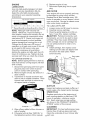
_i, WARNING:
This trimmer is equipped with an internal combustion
engine and should
not be used on or near any unimproved
forest-covered,
brush-covered
or grass-covered
land unless the engine's exhaust system is equipped with a spark arrester meeting applicable local or state laws (if any). If a spark arrester is used, it should be maintained
in
effective working order by the operator.
In the state of California
the above is required by law (Section 4442 of the California
Public Resources
Code).
Other states may have similar laws. Federal laws apply on
federal lands. A spark arrester for the muffler is available through your nearest Sears
service center (see the REPAIR PARTS section of this manual).
SAFETYGLASSES
The operation of any trimmer can result in foreign objects thrown into
the eyes, which can result in severe eye damage.
Always wear safety
glasses or eye shields while operating your trimmer or performing
any
adjustments
or repairs.
We recommend
standard
safety glasses or a
wide vision safety mask worn over spectacles.
&Look for this symbol to point out
important safety precautions. It means
CAUTIONN!
BECOME ALERT!N
YOUR SAFETY IS INVOLVED.
& WARNING:
In order to prevent accidental starting when setting up, transporting, adjusting
or making repairs,
always disconnect
spark plug wire and
2 place wire where
it cannot
contact
plug.
_i, WARNING:
Engine
exhaust,
some
of its constituents,
and certain vehicle
components
contain or emit chemicals
known to the State of California
to
cause cancer and birth defects or other
reproductive
harm.
A CAUTION:
Muffler and other engine
parts become extremely
hot during
operation
and remain hot after engine has
stopped. To avoid severe burns on contact,
stay away from these areas.
I. GENERAL
OPERATION
• Read, understand,
and follow all instructions on the machine and in the manual
before starting. Be thoroughly
familiar
with the controls and the proper use of
the machine before starting.
• Do not put hands or feet near or under
rotating parts.
• Keep all parts of your body away from
muffler and spinning line. A hot muffler
can cause serious burns.
• Only allow responsible
individuals,
who
are familiar with the instructions,
to
operate the machine.
• Stay away from breakable
objects, such
as house windows,
auto glass, greenhouses, etc.
• Clear the area of objects such as rocks,
toys, wire, bones, sticks, etc., which
could be picked up and thrown by the
spinning lines.
• Be sure the area is clear of other people
before trimming,
particularly
small children and pets. Stop machine if anyone
enters the area.
• Wear appropriate
clothing such as a
long-sleeved
shirt or jacket. Also wear
long trousers or slacks. Do not wear
shorts.
• Do not wear loose clothing which could
get caught in this equipment.
• Do not operate the machine when barefoot or wearing open sandals.
Always
wear work gloves and sturdy footwear.
Leather work shoes or short boots work
well for most people. These will protect
the operator's
ankles and shins from
small sticks, splinters,
and other debris,
and improve traction.
• Do not pull machine backwards
unless absolutely necessary. Always look down and
behind beforeandwhile
moving backwards.
• Do not operate the machine without
proper guards, plates or other safety
protective
devices in place.
• See manufacturer's
instructions
for
proper operation
and installation
of
accessories.
Only use accessories
approved by the manufacturer.
• Never use blades, wire, or flailing devices.
This unit is designed for line trimmer use
only. Use of other accessories
or attachments will increase the risk of injury.
• Stop the rotating trimmer head when
crossing gravel drives, walks, or roads.
Wait for the cutting lines to stop rotating.
• Stop the engine (motor) whenever
you
leave the equipment
and allow it to cool,
before cleaning,
repairing or inspecting
the unit. Be sure the trimmer head and
all moving parts have stopped.
• Operate only in daylight or good artificial
light.
• Do not operate the machine while under
the influence of alcohol or drugs.
• Never operate machine in wet grass. Always be sure of your footing: keep a firm
hold on the handle and walk; never run.
•
If the equipment
should start to vibrate
abnormally,
stop the engine (motor) and
check immediately
for the cause. Vibration is generally
a warning of trouble.
• Always wear safety goggles or safety
glasses with side shields when operating machine.
II.
SLOPE
OPERATION
Slopes are a major factor related to slip and
fall accidents which can result in severe injury.
All slopes require extra caution.
If you feel
uneasy on a slope, do not trim it.
DO:
• Trim across the face of slopes: never
and down.
Exercise extreme caution
when changing direction
• Remove obstacles
such
limbs, etc.
on slopes.
as rocks, tree
• Watch for holes, ruts, or bumps.
grass can hide obstacles.
DO
up
Tall
NOT:
• Do not trim near drop-offs,
ditches or
embankments.
The operator could lose
footing or balance.
• Do not trim excessively
steep slopes.
• Do not trim on wet grass. Reduced footing could cause slipping.
3
Ill. CHILDREN
Tragic accidents can occur if the operator is not alert to the presence of children. Children are often attracted to the
machine and the trimming activity. Never
assume
that children
will remain
where
you last saw them.
• Keep children out of the trimming
area
and under the watchful care of another
•
responsible
adult.
Be alert and turn machine
enter the area.
off if children
•
Before and while moving backwards,
look behind & down for small children.
•
Never allow
machine.
•
Use extra care when approaching
blind
corners, shrubs, trees, or other objects
that may obscure vision.
IV.
•
children
to operate
the
SERVICE
Use extra care in handling gasoline and
other fuels. They are flammable
and
vapors are explosive.
Use only an approved
container.
Never remove gas cap or add fuel with
with the engine running.
Allow engine
to cool before refueling.
Don't smoke.
Repair
Purchase
a Repair Protection
Agreement
now and protect yourseff from unexpected
hassle and expense.
•
•
•
•
what's
included
open flame, such as a water heater.
Move away from fueling site before
starting engine.
• Never run trimmer inside a closed area.
• Never make adjustments
or repairs with
the engine (motor) running. Disconnect
the spark plug wire, and keep the wire
away from the spark plug to prevent accidental starting.
• Keep nuts and bolts, especially
trimmer
head and engine bolts, tight and keep
equipment
in good condition.
• Never tamper with safety devices.
Check their proper operation
regularly.
• Keep machine free of grass, leaves, or
other debris buildup.
Clean oil or fuel
spillage.
Allow machine to cool before
cleaning or storing.
• Stop and inspect the equipment
if you
strike an object.
Repair, if necessary,
before restarting.
• Do not change the engine governor setting or overspeed
the engine.
• Clean and replace safety and instruction
decals as necessary.
Protection
Congratulations
on making a smart purchase. Your new Craftsman®
product is
designed
and manufactured
for years of
dependable
operation.
But like all products, it may require repair from time to
time. That's when having a Repair Protection Agreement
can save you money and
aggravation.
Here's
Never refuel the machine indoors.
Never store the machine or fuel
container
inside where there is an
in the Agreement:
Expert service
by our 12,000 profesional repair specialists.
Unlimited
service and no charge for
parts and labor on all covered repairs.
Product
replacement
if your covered
product can't be fixed.
Discount
of 10% from regular price of
service and service-related
parts not
covered by the agreement;
also, 10%
off regular price of preventive
maintenance check.
Agreements
•
Fast help by phone - phone support from a Sears representative
on
products requiring in-home repair, plus
convenient
repair scheduling.
Once you purchase
the Agreement,
a
simple phone call is all that it takes for you
to schedule
service. You can call anytime
day or night, or schedule
a service appointment online.
Sears has over 12,000 professional
repair
specialists,
who have access to over 4.5
million quality parts and accessories.
That's the kind of professionalism
you can
count on to help prolong the life of your
new purchase for years to come. Purchase
your Repair Protection Agreement
today!
Some limitations
and exclusions
apply.
For prices and additional
information
call 1-800=827-6655.
Sears
Installation
Service
For Sears professional
installation
of home
appliances,
garage door openers, water
heaters, and other major home items, in
the U.S.A. call 1=800=4=MY-HOME®.
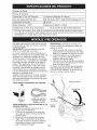
Serial Number:
Date of Purchase:
Gasoline Capacity / Type:
1.6 Quarts
Oil Type (API SG-SL):
SAE 30 (above
Oil Capacity:
20 Ounces
Spark
Plug (Gap:
Trimmer
Champion
Line Length:
• The model
Record
.030")
and serial
both serial
Read these
18.75
numbers
number
instructions
(Unleaded
will be found
in
on a decal
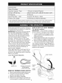
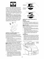
HOW
its entirety before you attempt to assemble
or operate your new trimmer,
iMPORTANT:
This trimmer is shipped WITHOUT OIL OR GASOLINE
in the engine,
Your new trimmer has been assembled
SAE 5W-30
(below
32°F)
or J19LM
(0.155
and date of purchase
and this manual
32°F);
RJ19LM
Inches
Regular)
Inch Diameter)
on the rear of the trimmer.
in the space
TO
SET
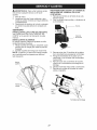
TO UNFOLD
iMPORTANT:
as not to pinch
provided
UP YOUR
above.
TRIMMER
HANDLE
Unfold handle carefully so
or damage control cables,
1,
Loosen handle knob enough to allow
upper handle to be unfolded from the
shipping position,
2, Raise upper handle section into place on
lower handle and tighten handle knob,
3, Remove handle padding holding trimmer head control bar to upper handle,
Your trimmer
handle can be adjusted for
your trimming
comfort,
Refer to "ADJUST
HANDLE"
in the Service and Adjustments
section of this manual,
at the factory with the exception
of those
parts left unassembled
for shipping
purposes,
All parts such as nuts, washers, bolts, etc,, necessary
to complete the
assembly
have been placed in the parts
bag, To ensure safe and proper operation
of your trimmer, all parts and hardware
you assemble
must be tightened
securely,
Use the correct tools as necessary
to
ensure proper tightness,
When right hand (RH) or left hand (LH) is
mentioned
in this manual, it means when
you are in the operating
position (standing
behind the handle),
Upper handle
Loose Parts Packed Separately
LIFT UP
Bottle
of oil
Trimmer
Lines
(0.155
x 18.75
REMOVE
TRIMMER
diameter
inches
Lower
handle
long)
FROM CARTON
1.
2.
Remove loose partsincluded
Cut down two end corners
3.
4.
and lay end panel down flat.
Remove all packing materials.
Roll trimmer out of carton and check carton thoroughly
Handle
knob
(2) Sets
for additional
with trimmer.
of carton
loose parts.
5
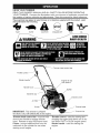
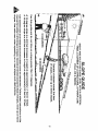
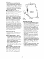
KNOW
READ
YOUR
THIS
TRIMMER
OWNER'S
MANUAL
AND ALL SAFETY
RULES
BEFORE
OPERATING
YOUR TRIMMER,
Compare
the illustrations
with your trimmer to familiarize
yourself with
the location of various controls and adjustments,
Save this manual for future reference,
These symbols may appear on your trimmer
and understand their meaning,
FAST
SLOW
or in literature
CAUTION
supplied
ENGINE OFF
"-
-Trimmer
with the product,
FUEL
Learn
OIL
AVOIDSERIOUS
INJURY
ORDEATH
head control bar
Throttle control
Starter handle
Engine oil cap
with dipstick
Handle knob
Muffler
Gasoline cap
Chassis cover
Primer
Trimmer head
IMPORTANT:
This trimmer is shipped
WITHOUT
OIL OR GASOLINE
in the engine.
Trimmer
head
control
bar - must be held
down to the handle to engage trimmer
head. Release to stop the trimmer head.
Primer - pumps additional fuel from the
carburetor
to the cylinder for use when
starting a cold engine.
Throttle
control
- used for starting and
stopping the engine and allows you to select either FAST or SLOW engine speed.
Starter
handle
- used for starting the
engine.
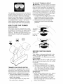
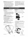
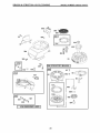
TO ADJUST TRIMMING HEIGHT
_CAUTION: Stop the engine and wait for
all moving parts to stop. Disconnect spark
plug wire from spark plug and place wire
where it cannot come in contact with plug.
The height of cut can be set to six (6) different positionsranging from 1-1/2 inches
to 3 inches. Recommendedcutting height
for the averageyard is 2 inches.
1. To adjust trimming height, push in the
locking plate tab and move trimmer
head up or down to desired position.
2. Releasetab and be sure head is
locked into one of the six (6) height
positions.
The operationof any trimmer can result in
foreign objects being thrown into the eyes,
which can result in severe eye damage.
Always wear safety glasses or eye shields
while operatingyour trimmer or performing
any adjustments or repairs. We recommend standard safety glasses or a wide
vision safety mask worn over spectacles.
HOW TO USE YOUR
ENGINE SPEED
TRIMMER
The engine speed is controlled by a throttle located on the side of the upper handle,
FAST position is for starting and normal
trimming, SLOW is for light trimming and
fuel economy, STOP is for stopping the
engine,
Adj
Trimmer
Head
Locking
Plate Tab
SLOW
FAST
\
/
\
1
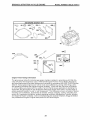
BEFORE
ADD
STARTING
ENGINE
OIL
Your trimmer
is shipped without oil in the
engine. For type and grade of oil to use,
see "ENGINE"
in the Maintenance
section
of this manual.
TRIMMER
HEAD
DRIVE
CONTROL
Ai_
oil,
on
1.
CAUTION:
DO NOT overfill engine with
or it will smoke heavily from the muffler
startup.
Be sure trimmer is level.
2.
3.
Remove oil dipstick from oil fill spout.
You receive a container of oil with the
unit. Slowly pour the entire container
down the oil fill spout into the engine.
4. Insert and tighten dipstick.
IMPORTANT:
• Check oil level before each use. Add oil
Your trimmer is equipped with a trimmer
head drive control bar which will require
the operator to be positioned
behind the
trimmer handle to operate the trimmer.
• Trimmer head rotation is controlled
by
holding the trimmer head control bar
down to the handle.
• Trimmer head rotation will stop when
the control bar is released.
7
if needed.
Fill to full line on dipstick.
• Change the oil after every 25 hours of
operation or each season.
You may
need to change the oil more often under
dusty, dirty conditions.
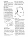
ADD GASOLINE
• Fill fuel tank to bottom of gas tank
filler neck. Do not overfill. Use fresh,
clean, regular unleadedgasoline with a
minimum
of 87 octane.
Do not mix oil
with gasoline.
Purchase
fuel in quantities that can be used within 30 days to
assure fuel freshness.
_IL CAUTION:
Wipe off any spilled
NOTE:
In cooler weather
it may be
necessary
to repeat priming steps.
In
warmer weather overpriming
may cause
flooding and engine will not start. If you
do flood engine, wait a few minutes before
attempting
to start and do not repeat
priming steps.
oil or
fuel. Do not store, spill or use gasoline
near an open flame.
J:IkCAUTION:
Alcohol blended fuels
(called gasohol or using ethanol or
methanol)
can attract moisture which
leads to separation
and formation
of acids
during storage. Acidic gas can damage
the fuel system of an engine while in
storage.
To avoid engine problems,
the
fuel system should be emptied before
storage of 30 days or longer.
Empty
the gas tank, start the engine and let it
run until the fuel lines and carburetor
are empty. Use fresh fuel next season.
See Storage Instructions
for additional
information.
Never use engine or
carburetor
cleaner products in the fuel
tank or permanent
damage may occur.
Gasoline filler
cap
ine
oil cap
Primer
TO STOP
ENGINE
• To stop engine, move throttle
lever to STOP position.
TO START ENGINE
1.
2.
3.
control
To start a cold engine, push primer three
(3) times before trying to start.
Use a
firm push. This step is not usually necessary when starting an engine which has
already run for a few minutes.
Move throttle control lever to FAST
position.
Hold upper handle firmly and pull
starter handle quickly.
Do not allow
starter rope to snap back.
Starter
handle
TRIMMING
TIPS
• Set the throttle control in the FAST position. If the weeds or grass are tall and
thick, operate the trimmer at a slower
walking speed.
• Frequently
clean the underside of the
trimmer to remove any grass build up.
Keep top of engine around starter clear
and clean of grass clippings
and chaff.
This will help engine air flow and extend
engine life.
• For best results and longer lasting line,
use the ends of the line to do the cutting.
This is easily done by moving slowly
through very thick and heavy weeds.
• Use the left side of trimmer when trimming along fences, walls, flowerbeds
and other such objects.
• If trimmer lines become too short, it will
take longer to complete the job. If trimmer lines are worn to less than half their
original length, they should be replaced.
See "TO REPLACE
TRIMMER
LINE" in
the Maintenance
section of this manual.
• Trimmer head contact with concrete,
asphalt or other hard surfaces may cause
premature
wear of the ball on bottom of
trimmer head.
.A.....A.C,
SC..OU',
F.....OATES
......
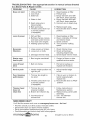
AS YOU COMPLETE
SERVICE
REGULAR
SERVICE
Check for Loose Fasteners
/__._OkXY
/__:x'_..,."4'r
I_
Clean Trimmer
Clean Under Engine Cover
_'_'- Z"
I_
I/
I/
I/'2
I_
v'
Check Drive Belt / Pulleys
R
DATES
Check / Replace Trimmer Lines
I/3
Check Engine Oil Level
I_
Change Engine Oil
I/'1,2
Clean Air Filter
Inspect Muffler
I_
Ii/'
2
Clean or Replace Spark Plug
Replace Air Filter Paper Cartridge
1_2
1 - Change more often when operating under a heavy load or in high ambient temperatures.
2 - Service more often when operating in dirty or dusty conditions.
3 - Replace trimmer lines when they have worn to half their original length.
GENERAL
•
RECOMMENDATIONS
The warranty on this trimmer does not
cover items that have been subjected to
operator abuse or negligence. To receive
full value from the warranty, operator must
maintain trimmer as instructed in this
manual.
Some adjustments will need to be made
periodically to properly maintain your unit.
At least once a season, check to see if
you should make any of the adjustments
described in the Service and Adjustments
section of this manual.
• At least once a year, replace the spark
plug and replace air filter element. A
new spark plug and clean/new air filter
element assure proper air-fuel mixture
and help your engine run better and
last longer.
Follow the maintenance
this manual.
BEFORE
EACH
1.
2.
Check
Check
engine oil level.
for loose fasteners.
3.
Clean
under engine
schedule
in
USE
cover.
LUBRICATION
To prolong the useful life of your trimmer,
change engine oil as recommended
in this
section of Owner's Manual,
IMPORTANT:
Do not oil or grease plastic
wheel
bearings.
Viscous
lubricants
will
attract dust and dirt that will shorten
the
life of the self- lubricating
bearings.
If you
feel they must be lubricated,
use only a dry,
powdered graphite type lubricant sparingly.
9
TRIMMER
Always
forming
TIRES
•
observe safety rules when
any maintenance.
per-
Keep tires free of gasoline, oil, or insect
control chemicals
which can harm rubber.
• Avoid stumps, stones, deep ruts, sharp
objects and other hazards that may
cause tire damage.
TRIMMER
LINE
For best results, replace trimmer lines
when they have worn to half their original
length. Use .155 inch diameter
trimmer
line. Cut new trimmer line length to 18-3/4
inches.
After new line is installed on
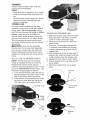
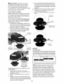
TO REPLACE
1.
trimmer head, check all lines so they do
not vary more then one (1) inch in length.
This is important to make sure the trimmer head is balanced and will not vibrate
2.
abnormally.
_kWARNING:
Use only the specified
trimmer line. Do not use other materials
3.
such as wire, string, rope, etc. Wire can
break off during trimming
and become a
dangerous
missile that can cause serious
injury.
4.
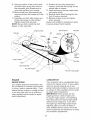
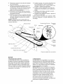
TO CUT LINE TO PROPER
LENGTH
5.
6.
NOTE: Trimmer line pre-cut to proper
length is available for this unit; see the
Repair Parts section of this manual.
If trimmer line is purchased
in bulk, it must
be cut to 18=3/4 inches
before using. Use
the built-in length guage as follows:
1. From front of trimmer, place the end of
spooled trimmer
line at the mark on the
side of the debris shield as shown.
2.
7.
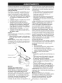
TRIMMER
LINE
Disconnect
spark plug wire
plug and place wire where
come in contact with spark
Remove worn trimmer line
from spark
it cannot
plug.
from line
carrier plate.
Fold new, cut to length, trimmer line
in half and insert folded end through
carrier plate opening to back side of
retainer clip.
With folded end of line at back side of
retainer clip, pull line outward until line
is fully seated under the retainer clip.
Repeat on other side of carrier plate.
Check all lines to be sure they are the
same length.
Reconnect
spark plug wire to spark
plug.
Trimmer
line
Wrap trimmer line around front of chassis cover to other side and cut at the
"22" mark
(your
unit's width
of cut).
Chassis cover
Carrier plate
opening
WRAP
LINE
_,ROUND
Debris
shield
mark
End of
spooled line
New
trimmer
line
Retainer
clip
10
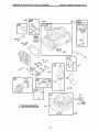
ENGINE
LUBRICATION
6.
7.
Use only high quality detergent
oil rated
with API service classification
SG-SL.
AIR
Select the oil's SAE viscosity grade
according
to your expected operating
temperature.
Replace engine oil cap.
Reconnect
spark plug wire to spark
plug.
FILTER
Your engine will not run properly and may
be damaged
by using a dirty air filter.
Replace the air filter cartridge every 100
hours of operation
or every season, whichever occurs first. Service air cleaner more
SAE VISCOSITY GRADES
often
F
-20
0
TEMPERATURE
30
RANGE
32
40
ANTiCiPATED
60
BEFORE
80
NEXT
100
OIL CHANGE
NOTE:
Although multi-viscosity
oils
(5W30, 10W30 etc.) improve starting in
cold weather, these multi-viscosity
oils will
result in increased
oil consumption
when
used above 32°F. Check your engine oil
level more frequently
to avoid possible
engine damage from running low on oil.
Change the oil after every 25 hours of
operation
or at least once a year if the unit
is not used for 25 hours in one year.
Check the crankcase
oil level before
starting the engine and after each five (5)
hours of continuous
use. Tighten oil plug
securely each time you check the oil level.
TO CHANGE
ENGINE
under dusty
conditions.
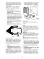
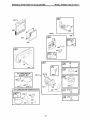
TO CLEAN
AIR FILTER
1.
screw
Loosen
and tilt cover to remove.
2.
3.
Carefully remove cartridge.
Clean by gently tapping on a flat surface. If very dirty, replace cartridge.
_I, CAUTION:
Petroleum
solvents,
such
as kerosene,
are not to be used to clean
cartridge.
They may cause deterioration
of the cartridge.
Do not oil cartridge. Do
not use pressurized
air to clean or dry
cartridge.
4. Install cartridge,
then replace cover
making sure the tabs are aligned with
the slots in the back plate. Fasten
screw securely.
Lip
Back plate
OIL
NOTE:
Before tipping trimmer to drain oil,
drain fuel tank by running engine until fuel
tank is empty.
1.
2.
3.
Disconnect
spark plug wire from spark
plug and place wire where it cannot
come in contact with spark plug.
Remove engine oil cap; lay aside on a
clean surface.
Tip trimmer on its side as shown
drain oil into a suitable container.
and
Rock
trimmer back and forth to remove
oil trapped inside of engine.
any
/
Cart_
Slot
Cover
tab
MUFFLER
Inspect and replace corroded muffler as it
could create a fire hazard and/or damage.
SPARK PLUG
Replace spark plug at the beginning
of
each mowing season or after every 100
hours of operation,
whichever
occurs
first. Spark plug type and gap setting
are shown in the "PRODUCT
SPECIFICATIONS" section of this manual.
Container
4.
5.
CLEANING
Wipe off any spilled oil from trimmer or
IMPORTANT:
For best performance,
keep
trimmer free of built-up grass and trash.
side of engine.
Clean the underside of your trimmer after
Fill engine with oil (See "ADD OIL" in
the Operation
section of this manual).
11 each use.
,_CAUTION:
Disconnect
spark plug wire
from spark plug and place wire where it
cannot come in contact with plug.
• Turn trimmer on its side. Make sure air
Keep finished surfaces
and wheels free
of all gasoline,
oil, etc.
We do not recommend
using a garden
hose to clean trimmer unless the elec-
filter and carburetor
are up. Clean the
underside of your trimmer by scraping to
remove build-up of grass and trash.
• Clean engine often to keep trash from
accumulating.
A clogged engine runs
hotter and shortens engine life.
trical system, muffler, air filter and carburetor are covered to keep water out.
Water in engine can result in shortened
engine life.
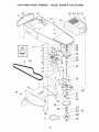
TO REMOVE/REPLACE
DRIVE BELT
A WARNING:
To avoid serious injury,
before performing any service and
adjustments:
1. Stop engine.
2. Make sure the rotating lines and all
moving parts have completely stopped.
3. Disconnect spark plug wire from spark
plug and place wire where it cannot
come in contact with plug.
1.
Remove
screw
TRIMMER
at front of chassis
cover,
2.
3.
Lift cover up and away from trimmer.
Remove the two (2) screws on sides of
Screw
TRIMMER
TO ADJUST TRIMMING HEIGHT
See "TO ADJUST TRIMMING HEIGHT" in
the Operation section of this manual.
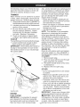
TO ADJUST
HEAD
Chassis
cover
HANDLE
The upper handle may be adjusted to different height positions.
• Loosen handle knob only enough to
allow the upper handle to pivot to the
desired position.
• Tighten handle knob securely.
NOTE: The handle knob and bolt may be
reversed for left handed operation.
4.
5.
6.
Upper handle
trimmer securing the debris shield.
Turn trimmer on its side with carburetor
and fuel cap up.
Remove the two (2) screws on underside of trimmer securing the debris
shield.
Slide the debris shield rearward and
remove.
7.
Remove belt from engine
crankshaft.
8.
Remove
belt from trimmer
pulley
on
head pulley.
EB¢
pulley
Handle knob
Debris shield screws
12
9.
Note the position of the control cable
and idler return spring, then remove
idler assembly
from chassis and remove belt and idler from trimmer.
12. Position belt and idler assembly
in
trimmer, reconnect
idler spring and assemble idler to chassis.
13. Install belt around trimmer
head pulley
and engine pulley.
14. Replace debris shield and tighten the
four (4) screws securely.
15. Replace chassis cover and tighten
screw securely.
Always use Craftsman
replacement
parts
to assure proper fit and long life.
10. Remove belt from idler assembly
by
removing
bottom belt keeper and idler
pulleys.
11. Assemble
new belt, idler pulleys and
bottom belt keeper to idler bracket.
Tighten pulley bolts securely.
NOTE: Be sure belt is inside top belt
keeper on idler assembly.
Idler bracket
Engine pulley
Chassis
Flat idler
Nut
-
" -. -..
/
Spacer
Spacer \
Idler
spring
I
I
•,.
\
-
_ _ "_'_
,,.
Bottom
.,
belt
keeper
Control cable
/
Belt
//_
Flat idler
" 2
Top belt keeper
Idler assembly
-. "
Bolt
Trimmer head pulley
ENGINE
ENGINE
/
CARBURETOR
SPEED
Your engine speed has been factory set.
Do not attempt to increase engine speed
or it may result in personal injury.
If you
believe that the engine is running too fast
or too slow, take your unit to a Sears or
other qualified service center for repair
and/or adjustment.
Your carburetor
has a nonadjustable
fixed
main jet for mixture control.
If your engine
does not operate properly due to suspected carburetor
problems,
take your unit
to a Sears or other qualified service center
for repair and/or adjustment.
IMPORTANT:
Never tamper with the
engine governor,
which is factory set
for proper engine speed.
Overspeeding
the engine above the factory high speed
setting can be dangerous.
If you think
the engine-governed
high speed needs
adjusting, take your unit to a Sears or
other qualified service center, which has
proper equipment
and experience
to make
any necessary
adjustments.
13
Immediately
prepare your trimmer for storage at the end of the season or if the unit
will not be used for 30 days or more.
TRIMMER
When trimmer
is to be stored for a period
of time, clean it thoroughly,
remove all dirt,
grease, leaves, etc. Store in a clean, dryarea.
1. Clean entire trimmer (See"CLEANING"
in
the Maintenance
section of this manual).
2. Lubricate
as shown in the Maintenance
section of this manual.
3.
Be sure that all nuts, bolts, screws, and
pins are securely fastened.
Inspect
moving parts for damage,
breakage
and wear. Replace if necessary.
4. Touch up all rusted or chipped paint
surfaces; sand lightly before painting.
HANDLE
You can fold your trimmer handle for storage.
• Loosen handle knob enough to allow
upper handle to be folded forward.
IMPORTANT:
When folding the handle for
storage or transportation,
be sure to fold
the handle as shown or you may damage
the control cables.
Also, alcohol blended fuels (called gasohol
or using ethanol or methanol)
can attract
moisture which leads to separation
and
formation
of acids during storage. Acidic
gas can damage the fuel system of an
engine while in storage.
• Empty the fuel tank by starting the engine and letting it run until the fuel lines
and carburetor
are empty.
• Never use engine or carburetor
cleaner
products in the fuel tank or permanent
damage may occur.
• Use fresh fuel next season.
NOTE:
Fuel stabilizer is an acceptable
alternative
in minimizing
the formation
of fuel gum deposits during storage.
Add stabilizer to gasoline in fuel tank or
storage container.
Always follow the mix
ratio found on stabilizer
container.
Run
engine at least 10 minutes after adding
stabilizer to allow the stabilizer to reach
the carburetor.
and carburetor
ENGINE OIL
Do not drain the gas tank
if using fuel stabilizer.
Drain oil (with engine warm) and replace
with clean engine oil. (See "ENGINE"
in
the Maintenance
section of this manual).
CYLINDER
1.
2.
3.
4.
Remove spark plug.
Pour one ounce (29 ml) of oil through
spark plug hole into cylinder.
Pull starter handle slowly a few times
to distribute oil.
Replace
with new spark
plug.
OTHER
• Do not store gasoline
to another.
from one season
• Replace your gasoline can if your can
starts to rust. Rust and/or dirt in your
gasoline will cause problems.
• If possible, store your unit indoors and
cover it to protect it from dust and dirt.
• Cover your unit with a suitable protective
cover that does not retain moisture.
Do
not use plastic.
Plastic cannot breathe,
which allows condensation
to form and
Handle knob
will cause your unit to rust.
IMPORTANT:
Never cover trimmer
ENGINE
engine and exhaust areas are still warm.
AI:ICAUTION:
Never store the trimmer
FUEL
SYSTEM
iMPORTANT:
It is important to prevent
gum deposits from forming in essential
fuel system parts such as carburetor,
fuel
filter, fuel hose or tank during storage.
while
with gasoline in the tank inside a building
where fumes may reach an open flame
or spark. Allow the engine to cool before
14 storing
in any enclosure.
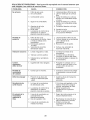
TROUBLESHOOTING
to a Sears
Parts
& Repair
PROBLEM
Does
- See appropriate
section
4. Water
1. Clean/replace
2. Fill fuel tank.
in fuel.
6. Bad spark plug.
7. Throttle control lever not
position.
1. Dirty air filter.
2. Buildup of grass, leaves,
and trash under trimmer.
3. Too much oil in engine.
4. Walking speed too fast.
Starter
rope
hard to pull
1. Bent engine
Loss
drive
of head
1. Belt not driving.
Hard
to push
1. Handle height
right for you.
Poor trimming
performance
head.
crankshaft.
1. Check trimmer lines.
2. Check all hardware,
including engine bolts.
3. Check/repair
trimmer head.
1. Contact
qualified
position
control
not
1. Trimmer
is
lever not
MORE
height
1. If line is worn or broken to
half of original length,
replace line.
,
Move throttle lever to FAST
line not
1. Follow instructions
in
Maintenance
section.
properly installed.
2. Broken line retainer
clip.
2. Replace string carrier
assembly,
3. Use .155 diameter
trimmer line,
HELP?
You'll
find the answer
•
•
•
•
this and all your other product manuals online.
answers from our team of home experts.
a personalized
maintenance
plan for your home.
information
and tools to help with home projects.
Find
Get
Get
Find
or other
center.
position.
3. Incorrect size of
trimmer line.
NEED
a Sears
service
1. Adjust handle
to suit.
in correct position
(if equipped),
Trimmer
head
does not
retain line
walking
1. Put belt on pulleys or
replace belt if broken.
1. Trimmer
line length
too short.
2. Throttle
1. Clean/replace
air filter.
2. Clean underside of trimmer
and trimmer head.
3. Check oil level.
4. Trim at slower
speed.
1. Lines uneven or broken.
2. Loose nuts or bolts.
trimmer
and refill
gasoline.
and refill
gasoline.
spark plug.
6. Replace spark plug.
7. Move throttle lever to FAST
in correct position
(if equipped).
3. Damaged
air filter.
3. Empty fuel tank
with fresh, clean
4. Empty fuel tank
with fresh, clean
5. Connect wire to
5. Spark plug wire is
disconnected.
Excessive
Vibration
directed
CORRECTION
1. Dirty air filter.
2. Out of fuel.
3. Stale fuel.
Loss of power
unless
Center.
CAUSE
not start
in manual
and more on managemyhome.com
15
= for free!
brought
to you by Sears
plate
m_
C
m
0
3-
C
m
0
_
_
_'_ _
_
_
°g
<
C
_N
16
Garantia ..........................................................
17
Reglas de Seguridad .................................
17-19
Especificaciones del Producto ........................ 20
Montaje / Pre-Operaci6n ................................
20
Operaci6n ..................................................
21-23
Mantenimiento ...........................................
24-26
Programa de Mantenimiento .......................... 24
Servicio y Adjustes ....................................
27-28
Almacenamiento .............................................
29
ldentificaci6n de problemas ............................ 30
Partes de repuesto ...................................
32-41
Servicio Sears ................................... Contratapa
GARANTiA LtM ITADA DE DOS ANOS PARA LA RECORTADORA PARA MALA HtERBA CRAFTSMAN
Por dos (2) a_os, a partir de la fecha de compra, cuando esta recortadora para mala hierba Craftsman se mantenga, lubrique y afine segQn las instrucciones para la operaci6n y el mantenimiento
en el manual del due_o, Sears reparara gratis todo defecto en el material y la mano de obra.
Si la recortadora para mala hierba Craftsman se usa para fines comerciales o de arriendo, esta
garantia s61o se aplica por noventa (90) dias a partir de la fecha de compra.
Esta Garantia no cubre:
Articulos que se desgastan durante el uso normal tales como las lineas rotatorias, las correas,
los filtros de aire y las bujias.
* Reparaciones necesarias debido al abuso o a la negligencia del operador, incluyendose a los
cigQe_ales doblados y a la falta de mantenimiento del equipo segQn las instrucciones que se
incluyen en el manual del due_o.
El servicio de garantia esta disponible al devolver la recortadora para mala hierba Craftsman al
Centro de Servicio Sears mas cercano en los Estados Unidos. Esta garantia se aplica solamente
mientras el producto este en uso en los Estados Unidos.
Esta Garantia le otorga derechos legales especificos,
que varian de estado a estado.
Sears,
Roebuck
and Co., Dept.
y puede que tambien tenga otros derechos
817 WA, Hoffman
Estates,
Illinois
60179
U.S.A.
ADVERTENClA:
Este recortadora viene equipado con un motor de combusti6n interna y no
se debe usar sobre, o cerca, de un terreno no desarrollado cubierto de bosques, de arbustos o
de cesped, o menos que el sistema de escape del motor venga equipado con un amortiguador de
chispas que cumpla con las leyes locales o estatales (si existen). Si se usa un amortiguador de
chispas, el operador debe mantenerlo en condiciones de trabajo eficientes.
En el estado de California, la ley exige Io anterior (Secci6n 4442 del "California Public Resources
Code"). Otros estados pueden contar con otras leyes parecidas. Las leyes federales se aplican en
la tierras federales. Su Centro/Departamento
de Servicio Sears mas cercano tiene disponible amortiguadores de chispas para el silenciador. (Vea la secci6n de Partes de Repuesto en el manual
Ingles del due_o.)
La operaci6n de cualquier recortadora puede hacer que salten objetos extra_os
dentro de sus ojos, Io que puede producir da_os graves en estos. Siempre use
anteojos de seguridad o protecci6n para los ojos mientras opere su recortadora o
cuando haga ajustes o reparaciones.
Recomendamos gafas de seguridad o una
mascara de visi6n amplia, de seguridad usada sobre las gafas.
_Busque
este simbolo que se_ala las precauproductos quimicos conocidos en el Estado de
ciones de seguridad de importancia. Quiere
California como causa de cancer y defectos al
decir - iJiATENCtON%iiESTE
ALERTO!H
,_cimiento u otros da_os reproductivos.
SU SEGURtDAD ESTA COMPROMETIDA.
PRECAUCION: El silenciador y otras
_IADVERTENClA:
Siempre desconecte el
piezas del motor Ilegan a sre extremadamente
alambre de la bujia y p6ngalo donde no pueda
calientes durante la operaci6n y siguen siendo
entrar en contacto con la bujia, para evitar el
calientes despues de que el motor haya parado.
arranque por accidente, durante la preparaci6n,
Para evitar quemaduras severas, permanezca
el transporte, el ajuste o cuando se hacen
lejos de estas areas.
_paraciones..
RECAUClON: El tubo de escape del motor,
algunos de sus constituyentes y algunos componentes del vehiculo contienen o desprenden
17
I. OPERAClON GENERAL
Antes de empezar, debe familiarizarse
completamente con los controles y el uso
correcto de la maquina. Para esto, debe leer
y comprender todas las instrucciones que
aparecen en la maquina yen los manuales
de operaci6n.
* No ponga las manos o los pies cerca o
debajo de las partes rotatorias.
* Mantener todas las partes del cuerpo lejos
del silenciador del escape y la linea de rotaci6n. El silenciador caliente puede causar
serias quemaduras.
Permita que solamente las personas responsables que esten familiarizadas con las
instrucciones operen la maquina.
* Mantenerse lejos de objetos que pueden
romperse, como cristales de casa, cristales
del choche, invernaderos, etc.
* Despeje el area de objetos tales como piedras, juguetes, alambres, huesos, palos, etc.
que pueden ser recogidos y lanzados por las
lineas giradoras.
* AsegOrese que el area no se hallen personas, y particularmente nifios pequefios y cachorros antes de recortar. Pare la maquina
si alguien entra en el area.
Use ropa apropaida, tal como camisa de
manga larga o chaqueta y pantalones largos.
No use pantalones cortos shorts.
No use ropa suelta, ya que esta podria atorarse en el equipo.
No opere la maquina sin zapatos o con sandalias abiertas. Use siempre guantes de trabajo
y calzado fuerte. Los zapatos de trabajo de
piel o botas cortas son apropiados para la
mayoria de las personas. Estos no s61o protegerian los tobillos y espinellas del operador de
pequefias ramas, astillas y otros desperdicios,
sino que ademas mejoraran la tracci6n.
* No tire de la maquina hacia atras a menos
que sea absolutamente necesario. Mire
siempre hacia abajo y hacia detras antes y
mientras que se mueve hacia atras.
* No opere la maquina sin los respectivos
resguardos, placas u otros aditamentos
disefiados para su protecci6n y seguridad.
* Refierase alas instrucciones del fabricante
para el funcionamiento e instalaci6n de
accesorios. Use Onicamente accesorios
aprobados por el fabricante.
* Nuca utilice cuchillas, cables o dispositivos
tipo mayal. Esta unidad esta proyectada
para fucionar solamente con una linea de
recortadora. La utilizaci6n de cualquier otro
material, acessorio o dispositivo secundario
aumenta el riesgo de lesi6nes y dafios a la
propiedad.
* Detenga la cabeza giratoria de la recortadora cuando cruce por calzadas, calles o
caminos de grava. Espere que las cuerdas
de corte paren de girar.
* Pare el motor siempre que tenga que dejar el
equipo, antes de limpiar, reparar o inspeccionar la unidad. AsegOrese de que la cabeza
de la recortadora y todas las partes en
movimiento se hayan detenido.
* Opere solamente con luz del dia o con una
buena luz artificial.
* No opere la maquina bajo la influencia del
alcohol o de las drogas.
* Nunca opere la maquina cuando la hierba
este mojada. AsegOrese siempre de tener
buena tracci6n en sus pies; mantenga el
mango firmemente y camine; nunca corra.
* Si el equipo empezara a vibrar de una
manera anormal, pare el motor y revise de
inmediato para averiguar la causa. Generalmente la vibraci6n suele indicar que existe
alguna averia.
* Siempre use gafas de seguridad o anteojos
con protecci6n lateral cuando opere la maquina.
II. OPERACION EN PENDIENTE
Los accidentes ocurren con mas frecuencia en
las cuestas. Estos accidentes ocurren debido a
resbaladas o caidas, las cuales pueden resultar
en graves lesiones. Operar la recortadora en
cuestas requiere mayor concentraci6n. Si se
siente inseguro en una cuesta, no la recorte.
SI:
Puede recortar a traves de la superficie de
la cuesta, nunca hacia arriba y hacia abajo.
Proceda con extrema precauci6n cuando
cambie de direcci6n en las cuestas.
* Renueva todos los objetos extrafios, tales
como guijarros, ramas, etc.
Debe prestar atenci6n a hoyos, baches o
protuberancias. Recuerde que la hierba alta
puede esconder obstaculos.
NO:
* No recorte cerca de pendientes, zanjas o
terraplenes. El operador puede perder la
tracci6n en los pies o el equilibrio.
No recorte cuestas demasiado inclinadas.
No recorte en hierba mojada. La reducci6n
en la tracci6n de la pisada puede causar
resbalones.
III. NINOS
Se pueden producir accidentes tragicos si el
operador no presta atenci6n a la presencia
de los nifios. A menudo, los nifios se sienten
atraidos por la maquina y por la actividad de
la siega. Nunca suponga que los nifios van a
permanecer en el mismo lugar donde los vio
por 01tima vez.
* Mantenga a los nifios alejados del area de
la siega y bajo el cuidado estricto de otra
persona adulta responsable.
* Este alerta y apague la maquina si hay nifios
que entran al area.
* Antes y durante el retroceso, mire hacia
atras y hacia abajo para verificar si hay nifios
pequeSos.
* Nunca permita que los nifios operen la maquina.
* Tenga un cuidado extra cuando se acerque
a esquinas donde no hay visibilidad, a los
arbustos, arboles u otros objetos que pueden
interferir con su linea de visi6n.
18
IV. SERVlCIO
* Tenga cuidado extra al manejar la gasolina y
los demas combustibles. Son inflamables y
los gases son explosivos.
Use solamente un envase aprobado.
Nunca remueva la tapa del dep6sito de
gasolina o agregue combustible con el
motor funcionando. Permita que el
motor se enfrie antes de volver a poner
combustible. No fume.
Nunca vuelva a poner combustible en
la maquina en recintos cerrados.
Nunca almacene la maquina o el
envase del combustible dentro de algOn
lugar en donde haya una llama expuesta, tal como la del calentador de agua.
* Alejarse de la zona de abastecimiento del
carburante antes de poner en marcha.
* Nunca haga funcionar una maquina dentro
de un area cerrada.
* Nunca haga ajustes o reparaciones mientras
el motor este en marcha. Desconecte el
Acuerdos
*
*
*
*
*
de Proteccibn
Congratulaciones por su buena compra. Su
nuevo producto Craftsman® esta diseSado
y fabricado para funcionar de modo fiable pot
muchos aSos. Pero como todos los productos,
puede necesitar alguna reparaci6n de tanto
en tanto. En este caso tener un Acuerdo de
Protecci6n para la Reparaci6n puede hacerles
ahorrar dinero y fastidios.
cable de la bujia, y mantengalo a cierta
distancia de esta para prevenir un arranque
accidental.
Mantenga las tuercas y los pernos, especialmente los pernos del motor y de la cabeza
de recortes, apretados y mantenga el equipo
en buenas condiciones.
Nunca manipule de forma indebida los
dispositivos de seguridad. Controle regularmente su funcionamiento correcto.
Mantenga la maquina libre de hierba, hojas u
otras acumulaciones de desperdicio. Limpie
los derrames de aceite o combustible. Permita que la maquina se refresque antes de
limpiarla o almacenarla.
Pare e inspeccione el equipo si le pega a un
objeto. Reparelo, si es necesario, antes de
hacerlo arrancar.
No cambie el ajuste del regulador del motor
ni exceda su velocidad.
Limpiar y sustituir las calcomanias relativas a
instrucciones y seguridad cuando necesario.
para la Reparacibn
Ayuda rapida pot tel_fono - soporte telef6nico por parte de un representento Sears
sobre productos que requieren un arreglo en
casa, y ademas una programaci6n sobre los
a reglos mas convenientes.
Cuando se ha comprado el Acuerdo, basta con
una Ilamada telef6nica para programar el servicio. Puede Ilamar cuando quiera, dia y noche o
fijar en linea una cita para obtener el servicio.
Sears tiene mas de 12.000 especialistas
profesionales en la reparaci6n, que tienen
acceso a mas de 4.5 millones de partes y
accesorios de calidad. Este es el tipo de
profesionalidad con que puede contar para
ayudar a alargar la vida del producto que acaba
de comprar, por muchos a_os. iCompre hoy su
Acuerdo de Protecci6n para la Reparaci6n!
Se aplican algunas limitaciones
y exclusiones. Para conocer los precios y tenet
mas informacion, Ilame al 1-800-827-6655.
Compre ahora un Acuerdo de Protecci6n para
la Reparaci6n y protegese de molestias y gastos inesperados.
Un Acuerdo incluye los puntos siguientes:
, Servicio experto de nuestros 12.000 especialistas profesionales en la reparaci6n.
, Servicio ilimitado sin cargo alguno para
las partes y la mano de obra sobre todas las
reparaciones garantizadas.
, Sustitucion
del producto si su producto
garantizado no puede ser arreglado.
* Descuento del 10% sobre el precio corriente del servicio y de las partes relativas al
servicio no cubiertas por el acuerdo; tambien
el 10% menos sobre el precio corriente de
un control de mantenimiento preventivo.
Servicio de Instalacion
Sears
Para la instalaci6n profesional Sears de
aparatos de casa, puertas de garaje,
calentadores de agua y otros importantes
articulos para la casa, en U.S.A. Ilamar a
1-800-4-MY-HOME®.
19
N6mero
Fecha
de Serie:
de Compra:
Capacidad
y Tipo de Gasolina:
Tipo de Aceite
Capacidad
Bujia
de Aceite:
(Abertura:
Longitud
(API SG-SL):
1.6 Cuartos
(Regular
SAE 30 (Sobre
sin Plomo)
32°F);
SAE 5W-30
(Debajo
32°F)
20 Onzas
.030")
Champion
de la linea de la recortadora:
RJ19LM
18.75
Inches
o J 19LM
(0.155
Inches
Diametro)
El n_mero del modelo y el de serie se encuentran en la calcomania adjunta a la parte trasera
de la caja de la recortadora. Debe registrar tanto el n_mero de serie come la fecha de compra y
mantengalos en un lugar seguro para refencia en el futuro.
Lea estas instrucciones y este manual completamente antes de tratar de montar u operar su
nueva recortadora.
IMPORTANTE: Esta recortadora viene SIN
ACEtTE O GASOLtNA en el motor.
Su nueva recortadora ha sido montada en la
fabrica con la excepci6n de aquellas partes que
se dejaron sin montar por razones de envio.
Todas las partes como las tuercas, las arandelas, los pemos, etc., necesarias para completar
el montaje han sido colocadas en la bolsa de
partes. Para asegurarse que su recortadora
funcione de forma segura y adecuada, todas
las partes y los articulos de ferreteda que se
monten tienen que ser apretados firmemente.
Use las herramientas correctas adecuadas para
asegurar un apretado firme.
Cuando la mano derecha o la mano izquierda
estan mencionadas en este manual, significa
que usted esta situado en la posici6n de operador, detras del mango.
IMPORTANTE: Despliegue el mango con
mucho cuidado para no apretar o da_ar los
cables de control.
1. Aflojar la perilla del mango Io suficiente
para permitir el mango superior ser desdoblado con respecto a la posici6n de envio.
2. Levante la secci6n del mango superior
hasta su lugar en el mango inferior, y
apriete la manilla del mango.
3. Remueva la cuba del mango que sujeta la
barra del control del cabezal de la recortadora al mango superior.
El mango de su recortadora puede ajustarse
segOn le acomode para recortar. Refierase
a "AJUSTE DEL MANGO" en la Secci6n de
Servicio y Ajustes de este manual.
Mango superior
Piezas sueltas empaquetadas pot separado
LEVANTAR
Botella
aeeite
de
2 Juegos de cuerda de
recortadora (0.155 de
di_rnetro × 18.75)
PARA REMOVER LA RECORTADORA
DE LA
CAJA DE CARTON
1. Remueva las partes sueltas que se incluyen con la recortadora.
2. Corte las dos esquinas de los extremos
de la caja de cart6n y tienda el panel del
extremo piano.
3. Remueva todo el material de embalaje.
4. Haga rodar la recortadora hacia afuera
de la caja de cart6n y revisela cuidadosamente para verificar si todavia quedan
partes sueltas adicionales.
Manilla
de mango
Mango
in_rior
2O
FAMILIARiCESE
CON SU RECORTADORA
LEA ESTE MANUAL DE USUARtO Y LAS REGLAS DE SEGURtDAD ANTES DE OPERAR SU
RECORTADORA. Compare las ilustraciones can su recortadora para familiafizarse con la ubicaci6n de los diversos controles y ajustes. Guarde este manual para referencia en el futuro.
Estos simbolos pueden aparecer sobre su recortadora
el producto.
Aprenda y comprenda
sus significados.
RA,PIDO
LENTO
ATTENCION
O
ADVERTENClA
o en las paginas
MOTOR
APAGADO
proporcionadas
COMBUSTIBLE
con
ACEITE
AVOIDSERIOUS
INJURYORDEATH
_Barra
Control
de la
Cordon
arrancador
de mando
del cabezal
de la recortadora
Tapa del deposito
de
aceite del motor con
indicadora
de nivel
Manilla
Tapa
de mang,
del deposito
de la gasolina
Filtro de
Cubierta del
chasis
Cabeza de la
recortadora
IMPORTANTE: Esta recortadora viene
SIN ACEtTE O GASOLINA en el motor.
Barra de mando del cabizal de la recortadora
- debe ser presionada hacia el mango para
enganchar el cabezal de la recortadora.
Cebadorbombea combustible adicional
desde el carburador al cilindro para uso cuando
se necesita hacer arrancar un motor frio.
21
Linea de la
recortadora
Control de la aceleracion
- se usa para hacer
arrancar el motor y le permite,seleccionar
la
velocidad del motor ya sea RAPIDA o LENTA.
Cordon arrancador - se usa para hacer arrancar el motor.
SEGURIDAD
Cabeza
recortadora
La operaci6n de cualquier recortadora puede
hacer que salten objetos extra_os dentro de
sus ojos, Io que puede producir dados graves
en estos. Siempre use anteojos de seguridad
o protecci6n para los ojos mientras opere su
recortadora o cuando haga ajustes o reparaciones. Recomendamos gafas de seguridad o una
mascara de visi6n amplia, de seguridad usada
sobre las gafas.
COMO UTILIZAR
Tabulacion
de la placa
de bloque
\
SU RECORTADORA
1
1
CONTROL DE LA VELOCIDAD DEL MOTOR
La velocidad del motor es controlada por una
valvula reguladora situada al lado del mango
superior. La posici6n R/kPIDA es para comenzar y para el recorte normal. LENTO es para
el recorte ligero y economizar combustible.
PARADA es para parar el motor.
ANTES
MOTOR
DE HACER
ARRANCAR
\
EL
AGREGUE ACEITE
Su recortadora fue enviada sin aceite en el motor. Para el tipo y el grado del aceite a utilizar,
vea el "MOTOR" en la secci6n del Mantenimiento de este manual.
_PRECAUCI6N:
NO sobrellene el motor con
LENTO
R,_PIDA
aceite, o fumar& pesa demante del silenciador
cuando Io valla a arrancar.
1. AsegQrese que la segadora este nivelada.
2. Remueva la varila medidora de aceite del tubo
de desarga de aceite.
3. Usted recibe un envase de aceite con la
unidad. Vierta lentamente el envase entero
de aceite en el tubo de relleno del motor.
4. lnserte y apriete la varilla medidora de
aceite.
IMPORTANTE:
* Revise el nivel del aceite antes de cada uso.
Agregue aceite si es necesario. Llene hasta la
linea de Ileno en la varilla medidora de nivel.
* Cambie el aceite despues de 25 horas de
operaci6n o una vez por temporada. Puede
necesitar cambiar el aceite mas a menudo cuando las condiciones son polvorosas o sucias.
CONTROL DE LA IMPULSION DEL CABEZAL DE LA RECORTADORA
Su recortadora viene equipada con una barra
de control de la impulsi6n del cabezal de la
recortadora que requiera que el operador este
colocado detras de la palanca de la recortadora
para operar la misma.
La rotaci6n del cabezal de la recortadora se
controla manteniendo la barra de control del
cabezal hacia abajo al mango.
• La rotaci6n del cabezal de la recortadora se
parara cuando la barra de control sea soltada.
PARA AJUSTAR ALTURA DEL RECORTE
,_PRECAUCl6N:
Pare el motor y espere hasta
que todas la piezas m6viles se hayan detenido
completamente.
Desconecte el alambre de la
bujia de la bujia y p6ngalo en donde no pueda
entrar en contacto con esta. La altura del corte
puede ser fijada en seis (6) diversas posiciones
que se extienden a partir de 1-1/2 pulgadas a 3
pulgadas. La altura de corte recomendada para
un cercado normal es 2 pulgadas.
1. Para ajustar la altura del recorte, empuje
la aleta tabulaci6n de la placa de bloque y
mueva el cabezal de la recortadora hacia
arriba o hacia abajo a la posici6n deseada.
2. Suelte la aleta y asegQrese que el cabezal
este situado en una de las seis (6) posiciones de la altura.
Tapa
del rellenador
de gasolina
Tapa del
deposito
de aceite
Cebador
22
GASOLINA
Llene el estanque de combustible hasta
la parte inferior del cuello de relleno del
estanque de gasolina. No Io Ilene demasiado.
Use gasolina regular, sin plomo, nueva y limpia con el minimo de 87 octanos. No mezcle
el aceite con la gasolina. Para asegurar
que la gasolina utilizada sea fresca compre
estanques los cuales puedan ser utilizados
, durante los primeros 30 dias.
PRECAUClON: Limpie el aceite o el
combustible derramado. No almacene, derrame
o use gasolina cerca de una llama expuesta.
,_;_PRECAUClON: Los combustibles
\
mezclados con alcohol (conocidos como
gasohol, o el uso de etanol o metanol) pueden
atraer la humedad, la que conduce a la
separaci6n y formaci6n de acidos durante el
almacenamiento. La gasolina acidica puede
daSar el sistema del combustible de un motor
durante el almacenamiento. Para evitar los
Cordon
arrancador
problemas con el motor, se debe vaciar el
sistema del combustible antes de guardarlo
por un periodo de 30 dias o mas. Vacie el
estanque del combustible, haga arrancar el
motor y hagalo funcionar hasta que las lineas
del combustible y el carburador queden vacios.
La pr6xima temporada use combustible nuevo.
Vea las lnstrucciones Para El AImacenamiento
para mas informaci6n. Nunca use productos de
limpieza para el motor o para el carburador en
el estanque del combustible pues se pueden
producir daSos permanentes.
AVISO PARA RECORTAR
. Fije el control de la aceleraci6n a la posici6n
RAPIDA. Si las malas hierbas o el cesped
estan altos y gruesos, opere la recortadora a
una velocidad de paso mas lento.
. Limpie con frecuencia la superficie inferior de
la recortadora para remueva cualquier acumulaci6n de hierba. Mantenga la superficie
del motor alrededor del arrancador despejado y limpio de recortes. Esto facilitara el flujo
de aire de motor y alargara la vida del motor.
. Para mejores resultados y una linea duradera, utilice los extremos de la linea para
hacer el corte. Esto se puede hacer con
facilidad al mover lentamente traves de las
malas hierbas.
. Utilizar el lado izquierdo de la recortadora
cuando se recortan recintos, paredes, parterres y otros objetos de ese tipo.
. Si las lineas de la recortadora se vuelven
cortas, se necesitara mas tiempo para terminar el trabajo. Si la linea de la recortadora se
desgasta a menos de la mitad de su Iongitud
original, debe ser substituida. Vea "PARA
SUBSTtTUtR LA LiNEA DE LA RECORTADORA" en la secci6n del Mantenimiento de
este manual.
. El contacto del cabezal con hormig6n, asfalto
u otras superficies duras puede causar el
desgaste prematuro de la bola en la parte
inferior del cabezal de la recortadora.
PARA PARAR EL MOTOR
Para parar el motor, mueva la palanca de
control de la aceleraci6n a la posici6n de
PARADA.
PARA HACER ARRANCAR EL MOTOR
1. Para hacer arrancar un motor frio, empuje
el cebador tres (3) veces antes de iniciar.
Empuje firmemente. Este paso normalmente no es necesario cuando se hace
arrancar un motor que ya ha estado funcionando por unos cuantos minutos.
2. Mueva la palanca de control de la aceleraci6n a la posici6n mas R/kPtDA.
3. Sujete la barra de control superior y tire del
mango del arrancador rapidamente. No permita que el cord6n arrancador se devuelva
abruptamente.
AVtSO: En climas mas frios puede que sea
necesario repetir los pasos del cebado. En
climas mas calurosos el cebar demasiado
puede producir el ahogo y el motor no va a
arrancar. Si se ahoga el motor espere unos
cuantos minutos antes de tratar de hacerlo
arrancar y no repita los pasos del cebado.
23
,.OO.A.A
°."A"T'"'"""'O
A MEDIDA
QUE
COMPLETE
/__'/_._y
BB
Revisar si hay sujetadores
sueltos
FECHAS
_
_
Limpiar la recortadora
I_'
_
Limpiar debajo de la cubierta del motor
0
Revisar las correas y las poleas
impulsadas
R
A
Verifique / reemplazar
de la recortadora
M
Cambiar
las lineas
Revisar el nivel del aceite
t_ 2
If
If
ip#_3
I_
el aceite del motor
_1,2
Limpiar el filtro de aire
Inspeccionar el silenciador
Limpiar o / cambiar
f f, J
K2
la bujia
Cambiar el cartucho
de papel del filtro de aire
1_2
1 - Cambiar ma.s a menudo cuando se opere bajo carga pesada o en ambientes con altas temperaturas.
2 - Dar servicio mgLs a menudo cuando se opere en condiciones sucias o polvorosas.
3 - Reernplazar
las I[neas de la recortadora cuando se hayan gastado hasta la mitad de su largura original.
RECOMENDACIONES
GENERALES
La garantia de esta recortadora no cubre los
articulos que han estado sujetos al abuso o a la
negligencia del operador. Para recibir todo el
valor de la garantia, el operador tiene que mantener la recortadora segOn las instrucciones
descritas en este manual.
Hay algunos ajustes que se tienen que hacer
en forma peri6dica para poder mantener su
unidad adecuadamente.
Todos los ajustes en la secci6n de Servicio y
Ajustes de este manual tienen que ser revisados por Io menos un vez por cada temporada.
* Una vez al a_o, cambie la bujia y el elemento del filtro de aire. Una bujia nueva y
un elemento del filtro de aire limpio/nuevo
aseguran la mezcla de aire-combustible
adecuada y ayudan a que su motor funcione
mejor y que dure mas.
Siga el programa de mantenimiento
manual.
en este
ANTES DE CADA USO
1. Revise el nivel del aceite del motor.
2. Revise si hay sujetadores sueltos.
3. Limpiar debajo de la tapa del motor.
LUBRICACI6N
Para prolongar la vida de su recortadora, cambie el aceite del motor como recomendado de
esta section de esta manual..
IMPORTANTE: No aceite o engrase los
rodamientos de la rueda de plastico. Los
lubricantes viscosos atraeran polvo y mugre,
Io que acortara la duraci6n de los rodamientos
auto lubricantes. Si cree que se tienen que
lubricar, use solamente un lubricante tipo
grafito, de polvo seco, en forma moderada.
LiNEA DE LA RECORTADORA
Para un rendimiento 6ptimo, reemplazar las lineas
de la recortadora cuando se hayan gastado hasta
la mitad de su largura original. Utilice una linea
de recortadora de 155 inch de diametro. Corte
la nueva linea de la recortadora de 18-3/4 inch.
Tras instalar la nueva linea en el cabezal de la
recortadora, controle todas las lineas para que
la diferencia entre elias no sea mayor de un (1)
inch. Esto es importante para asegurarse de que
el cabezal de la recortadora este balanceado y
no vibre de modo an6malo.
RECORTADORA
Siempre observe las reglas de seguridad cuando haga el mantenimiento.
LLANTAS
. Mantenga las Ilantas sin gasolina, aceite o
substancias quimicas para control de insectos que pueden daSar la goma.
. Evite los tocones, las piedras, las grietas profundas, los objetos afilados y otros peligros
que pueden daSar alas Ilantas.
24
,If_PRECAUCI6N:
Utilice s61o la linea de
recortadora recomendada. No utilice otros
materiales como cables, cuerdas, cintas,
etc. un cable podria romperse durante el
funcionamiento y volverse un peligroso cohete
que podria causar heridas serias.
PARA CORTAR LA LiNEA
A LA LONGITUD APROPtA
NOTA: La linea de la recortadora precortada
a la Iongitud apropiada esta disponible para
esta unidad; vea la secci6n de las Piezas de
Recambio de este manual.
4.
5.
6.
7.
Con la extremidad de la linea plagada en el
lado trasero del clip del sujetador, empujar
la linea hacia afuera hasta que la linea este
completamente colocada debajo del clip del
sujetador.
Repetir en el otto lado de la placa portante.
Controlar las lineas para asegurase que
sean de la misma largura.
Vuelva a conectar el alambre de la bujia a
esta.
Linea de la
recortadora
Si la linea de la recordadora se compra a por
mayor, debe ser cortada a 18-3/4 pulgadas
antes de usar. Utilice la medida de Iongitud
incorporada como sigue:
1. Del frente de la recortadora, ponga el extremo de la linea encanillada de la recortadora en la marca en la cara del blindaje de
escombros segOn Io mostrado.
2. Envuelva la linea de la recortadora alrededor del frente de la cubierta del chasis
a la otra cara y c6rtela en la marca "22"
(anchura de corte de su unidad).
Apertura de la
placa portante
Cubierta
chasis
ENVUELVA
LA
LiNEA
ALREDEDOR
Marca
del
blindaje de
escombros
Clip del
sujetador
Nueva
Extremc
de la linea
encanillada
MOTOR
LUBRICACiON
linea de la
recortadora
Use solamente aceite de detergente de alta calidad clasificado con la clasificaci6n SG-SL de servicio APt. Seleccione la calidad de viscosidad SAE
segQn su temperatura de operaci6n esperada.
SAE VlSCOSITY
-20
c J0
0
-20
TEMPERATURE
PARA REEMPLAZAR LAS LiNEA DE LA RECORTADORA
1. Desconecte el alambre de la bujia y
p6ngalo de modo que no pueda entrar en
contacto con esta.
2. Remover la I[nea gastada de la placa portante.
3. Plegar en dos la nueva linea cortada a la
medida e introducir la extremidad plegada a
traves de la placa portante abriendo el lado
trasero del clip del sujetador.
30
-1;
RANGE
32
GRADES
40
;
ANTICIPATED
60
1'0
BEFORE
80
10
100
_0
4;
NEXT OIL CHANGE
AVlSO: A pesar de que los aceites de multiviscosidad (5W30, 10W30, etc.) mejoran el
arranque en clima frio, estos aceites de multiviscosidad van ha aumentar el consumo de
aceite cuando se usan en temperaturas sobre
32 ° F. Revise el nivel del aceite del motor mas a
menudo, para evitar un posible da_o en el motor, debido a que no tiene suficiente aceite.
Cambie el aceite despues de 25 horas de
operaci6n o por Io menos una vez al a_o si la
recortadora se utiliza menos 25 horas el a_o.
25
Revise el nivel del aceite del carter antes de
arrancar el motor y despues de cada cinco (5)
horas de uso continuado. Apriete el tap6n del
aceite en forma segura cada vez que revise el
nivel del aceite.
4.
lnstale el cartucho, luego vuelva a poner la
cubierta asegurandose que las orejas esten
alineadas con las ranuras en la plancha
trasera. Apriete el tornillo en forma segura.
Labio
PARA CAMBtAR EL ACEITE DEL MOTOR
AVlSO: Antes de inclinar la recortadora
para drenar el aceite, drene el tanque de
combustible haciendo funcionar el motor hasta
que el tanque este vacio.
1. Desconecte el alambre de la bujia y
p6ngalo de modo que no pueda entrar en
contacto con esta.
2. Remueva la tapa del dep6sito del aceite;
dejela a un lado en una superficie limpia.
3. Incline la recortadora y hagala descansar en
su lado y drene el aceite en un envase adecuado. Mueva la recortadora de atras para
adelante para remover todo el aceite que se
haya quedado atrapado dentro del motor.
4. Limpie todo el aceite derramado en la
recortadora yen el lado del motor.
5. Llene el motor con aceite (Vea "AGREGUE
ACEtTE" en la secci6n de Operaci6n de
este manual).
6. Vuelva a poner la tapa en el dep6sito del
aceite.
7. Vuelva a conectarel alambre de la bujia a esta.
Plancha
trasera
Cartucho
j/
Ranuras
Cubierta
Or_as de
la cubierta
SlLENClADOR
lnspeccione y cambie el silenciador si esta
corroido pues producir un peligro de incendio
y/o da_o.
BUJ{A
Cambie el bujia al comienzo de cada temporada de siega o despues de cada 100 horas
de operaci6n, Io que suceda primero. El tipo de
bujia y el ajuste de la abertura aparecen en "ESPECtFICACtONES
DEL PRODUCTO" secci6n
de este manual.
LIMPIEZA
IMPORTANT: Para obtener el mejor
rendimiento, mantenga la caja de la recortadora
sin acumulaci6n de cesped y residuos. Limpie
la parte de su recortadora despues de cada
USO.
Envase
_,PRECAUCl6N:
FILTRO DE AIRE
Su motor puede sufrir averias y funcionar de
manera incorrecta con un filtro del aire sucio.
Sustituir el papel del cartucho una vez al aSo
o tras 100 horas de funcionamiento, mas a
menudo si se utiliza en condiciones de suciedad y polvo particulares.
PARA LIMPtAR EL FtLTRO DE AIRE
Desconecte
el alambre de
la bujia y p6ngalo en donde no pueda entrar en
contacto con esta.
.
Haga descansar la recortadora en su lado.
AsegQrese que el filtro de aire y que el carburador queden mirando hacia arriba. Limpie la
parte inferior de su recortadora raspandola para
remover la acumulaci6n de cesped y residuos.
. Limpie el motor a menudo para evitar la
acumulaci6n de residuos. Un motor tapado
funciona a temperatura mas alta y se acorta
su duraci6n.
. Mantenga las superficies limpias y las ruedas
sin gasolina, aceite, etc.
. No recomendamos el uso de una manguera
de jardin para limpiar la recortadora a menos
que el sistema electrico, el silenciador, el
filtro de aire y el carburador esten tapados
para evitar que les entre el agua. El agua en
el motor puede acortar la duraci6n de este.
1.
Suelte el tornillo e incline la cubierta para
removerlo.
2. Cuidadosamente, remueva el cartucho.
3. Limpielo golpeandolo suavemente en una
superficie plana. Siesta muy sucio cambie
el cartucho.
_ILPRECAUClON:
Los solventes de petr61eo,
tales como el keroseno, no se deben usar para
limpiar el cartucho. Pueden producir el deterioro
de este. No aceite el cartucho. No use aire a
presi6n para limpiarlo o secarlo.
26
ADVERTENClA:
PARA REMOVER/AJUSTAR
LA CORREA DE
IMPULSION DEL CABEZAL DE LA RECORTADORA
1. Remueva el tomillo en el frente de la cubierta del chasis.
2. Gire la cubierta hacia arriba y a distancia de
la recortadora.
Para evitar lesi6nes serias
ntes de dar cualquier sercicio o de hacer
ajustes:
1. Pare el motor.
2. AsegQrese que las lineas rotatorias y que
todas las partes movibles se hayan detenido
completamente.
3. Desconecte el alambre de la bujia y p6ngalo
en donde no pueda entrar en contacto con
esta.
Tornillo
SEGADORA
PARA AJUSTAR LA ALTURA DEL RECORTE
Vea "PAPA AJUSTAR LA ALTURA DEL RECORTE" en la secci6n de Operaci6n de este
manual.
Cubierta
del chasis
PARA AJUSTAR EL MANGO
El mango superior puede set ajustado en diferentes posiciones de altura
1. Afloje la perilla del mango Io suficiente para
permitir que el mango gire hasta la posici6n
deseada.
2. Apriete la perilla del mango de modo firme.
NOTA: La parrilla y la perno del mango pueden
ser invertidos para las operaciones sobre el
lado izquierdo.
3.
4.
5.
Mango
superior
6.
7.
Remueva los dos (2) tornillos de los lados
de la recortadora que aseguran el blindaje.
Ponga la recortadora en su lado con el
carburador y con el tap6n del combustible
hacia arriba.
Remueva los dos (2) tornillos de la parte
inferior de la recortadora que aseguran el
blindaje.
Desliza el blindaje hacia atras y remuevalo.
Remueva la correa de la polea del motor
sobre el cigOefial.
mango
Polea
del
motor
Tornillos del blindaje
27
8.
Remueva la correa de la polea del cabezal
de la recortadora.
9. Observe la posici6n del cable de control y
del resorte de Ilamada del piton Ioco. A
continuaci6n remueva el conjunto del piton
Ioco del chasis y remueva la correa y el
piton Ioco de la recortadora.
10. Remueva la correa del conjunto del pidon
Ioco al remover el fijador de correa inferior y
las poleas del piton.
11. Monte la nueva correa, las poleas del pidon
Ioco y el fijador de correa inferior al soporte
del piton. Apriete los pemos de la polea
con seguridad.
AVlSO: AsegOrese que la correa este en el
interior del fijador de la correa superior sobre el
conjunto del pi_6n.
Polea
12. lnstale la correa y el conjunto del piSon Ioco
en la recortadora, vuelva a conectar un
resorte del piSon Ioco y monte el piSon Ioco
al chasis. Apriete con seguridad.
13. lnstale la correa alrededor de la polea del
cabezal de la recortadora y de la polea del
motor.
14. Substituya el blindaje y apriete los cuatro
(4) tornillos con seguridad.
15. Substituya la cubierta del chasis y apriete el
tornillo con seguridad.
Utilice siempre las piezas de recambio Craftsman para asegurar un ajuste adecuado y una
vida larga.
Conjunto
del motor
Espaciador
del pit_6n Ioco
Engranaje
piano
\
Fijador
de correa
inferior
"-,,_.,
Cable de control
J
Conjunto del pi5dn Ioco
Fijador
de la correa
/
Engranaje
piano
" "--...
/
superior
/.
Boulon
Polea
del cabezal
de la recoriadora
MOTOR
VELOCIDAD DEL MOTOR
La velocidad del motor ha sido ajustada en
la fabrica. No trate de aumentar la velocidad
del motor pues se pueden producir lesiones
personales. Si cree que el motor esta funcionando demasiado rapido o demasiado lento,
Illeve su unidad a un centro de servicio Sears o
a un otro centro de servicio cualificado para la
reparaci6n y/o el ajuste.
CARBURADOR
Su carburador no es ajustable. Si su motor no
esta funcionando en forma adecuada debido
a problemas que se sospecha vienen del carburador, Ileve su unidad a un centro de servicio
Sears o a un otro centro de servicio cualificado
para la reparaci6n y/o el ajuste.
IMPORTANTE: Nunca manipulee el regulador
del motor, el que ha sido ajustado en la fabrica
para la velocidad del motor adecuada. Puede
ser peligroso hacer funcionar el motor a una
velocidad por sobre el ajuste de alta velocidad
de la fabrica. Si cree que la velocidad alta
regulada del motor necesita ajuste, leve su
unidad a un centro de servicio Sears o a un
otro centro de servicio cualificado, el que
cuenta con el equipo adecuado y la experiencia
para hacer los ajustes necesarios.
28
formaci6n de acidos durante almacemamiento.
la gasolina acideca puede nafiar el sistema de
combustible de un motor durante el perido de
alcamenmiento.
Prepare inmediatamente su recortadora para el
alma cenamiento al final de cada temporada o
si la unidad no se va a usar por 30 dias o mas.
RECORTADORA
Cuando se va a guardar la recortadora por un
cierto periodo de tiempo, limpiela cuidadosamente, remueva toda la mugre, la grasa, las
hojas, etc. Guardela en un area limpia y seca.
1. Limpie toda la recortadora (Vea "LtMPtEZA"
en la secci6n de Mantenimiento de este
manual).
2. Lubriquela segOn se muestra en la secci6n
de Mantenimiento de este manual.
3. AsegOrese de que todas las tuercas y
clavijas y todos los pernos y tomillos esten
apretados en forma segura, lnspeccione
las partes que se mueven para verificar si
estan dafiadas, quebradas o desgastadas.
Cambielas si es necesario.
4. Retoque todas las superficies que esten
oxidadas o con la pintura picada; use una
lija antes de pintar.
MANGO
Usted puede plegar el mango de su recortadora
para el almacenaje.
* Afloje la perilla del mango Io suficiente para
permitir al mango superior ser plegado hacia
adelante.
IMPORTANTE: Cuando doble el mango para
el alacenamiento o el trasporte, asegurese que
Io doble segun se muestra o puede danar los
cables de control.
.
_$2Z2
=
, Vaciar el dep6sito del carburante poniendo
en marcha el motor y dejandolo funcionar
hasta que el carburante termine y el
carburador este vacio.
, Nunca use los productos para limpieza del
carburador o del motor en el estanque de
combustible pues se pueden producir dafios
permanentes.
, Use combustible nuevo la pr6xima temporada.
AVISO: El estabilizador de combustible es
una alternativa aceptable para reducir a un
minimo la formaci6n de dep6sitos de goma
en el combustible durante el periodo de
almacenamiento. Agregue estabilizador a la
gasolina en el estanque de combustible o en
el envase para el almacenamiento. Siempre
siga la proporci6n de mezcla que se encuentra
en el envase del estabilizador. Haga funcionar
el motor por Io menos 10 minutos despues de
agregar el estabilizador, para permitir que este
Ilegue al carburador. No drene la gasolina del
estanque de gasolina y el carburador si se esta
usando estabilizador de combustible.
ACEITE DEL MOTOR
Drene el aceite (con el motor caliente) y cambielo
con aceite de motor limpio. (Vea "MOTOR" en la
secci6n de Mantenimento de este manual.)
CILINDRO
1. Remueva la bujia.
2. Vacie una onza (29 ml) de aceite a traves
del agujero de la bujia en el cilindro.
3. Tire la manilla de arranque lentamente unas
cuantas veces para distribuir el aceite.
4. Vuelva a montar la nueva bujia.
,,
OTROS
,
Mango
suF
Manilla
de
No guarde la gasolina de una temporada a la
otra.
, Cambie el envase de la gasolina si se empieza a oxidar. La oxidaci6n y/o la mugre en
su gasolina produciran problemas.
, Si es posible, guarde su unidad en un recinto
cerrado y cObrala para protegerla contra el
polvo y la mugre.
, Cubra su unidad con un forro protector
adecuado que no retenga la humedad. No
use plastico. El plastico no puede respirar, Io
que permite la formaci6n de condensaci6n,
Io que producira la oxidaci6n de su unidad.
IMPORTANTE: Nunca cubra la recortadora
mientras el motor y las areas de escape todavia
estan calientes.
,I_PRECAUCI6N:
Nunca almacene la
mango
MOTOR
SISTEMA DE COMBUSTIBLE
IMPORTANTE: Es importante evitar que se
formen depositos de partes fundamentales
del sistema de comustible tales como el
carburador, el filtro del combutible, la manguera
del combustible o en el estanque durante el
almacenmiento. Los combustibles mezclados
con alcohol (conocido come gasohol o que
tienen etanol o metanol) pueden atraer
humedad, Io que conduce a la separati6n y a la
recortadora con gasolina en el dep6sito dentro
de un edificio en donde los gases pueden
alcanzar una llama expuesta o una chispa.
Permita que se enfrie el motor antes de
almacenarla en un lugar cerrado.
29
SOLUCION
DE PROBLEMAS
- Vea la secci6n
est_ dirigido
a un centro de servico
Sears.
PROBLEMA
No arranca
apropiada
CAUSA
rancio.
4. Agua en el combustible.
5. Alambre de la bujia
desconectado.
6. Bujia mala.
7. La palanca de control de la
aceleraci6n no esta en
posici6n correcta (si existe).
P_rdida de
potencia
Vibraci6n
excesiva
arnenos
que
CORRECCION
.
Filtro de aire sucio.
2. Sin combustible.
3. Combustible
en el manual
1. Limpie/cambie el filtro de aire.
2. Llene el estanque de combus
tible.
3. Vaciar el estanque y vuelva a
Nenarlo con combustible limpio
y nueva.
4. Vaciar el estanque y vuelva a
Nenarlo con combustible limpio
y nueva.
5. Conecte el alambre a la bujia.
6. Cambie la bujia.
7. Mover la palanca de aceleraci6n
en la posici6n RAPIDA.
1. Filtro de aire sucio.
2. Acumulaci6n de hierba, hojas
y residuos debajo de la
recortadora.
3. Demasiado aceite en
el motor.
4. Velocidad de recorrido
demasiado rapida.
1. Limpie/cambie el filtro de aire.
2. Limpiar debajo de la recortadora
y del cabezal de la
recortadora.
3. Revise el nivel del aceite.
1. Lineas irregulares
1. Controlar las lineas de la
recortadora.
2. Controlar toda la ferreteria,
incluidos los pernos del motor.
3. Controlar/arreglar el cabezal de
la recortadora.
o rotas.
2. Tuercas o pernos sueltos.
3. Cabezal de la recortadora
da_ado.
4. Corte a una velocidad de
recorrido mas lenta.
Cordon
arrancador
dificil de tirar
1. CigQe_al del motor plegado.
P_rdida de
movimiento
del cabezal
1. Correa que no marcha.
1. Colocar la correa en las poleas
o reemplazar la correa siesta
rota.
Dificil de empujar
1. Posici6n de la altura del
mango no adecuada para
usted,
1. Ajuste la altura del mango de
modo que le
acomode.
Rendimiento
de
corte escaso
1. La Ifnea de la recortadora
es demasiado corta.
1. Si la linea esta gastada o rota
hasta la mitad de su largura
original, reemplazar la linea.
2. Mover la palanca de
aceleraci6n en la posici6n
RAPIDA.
2. La palanca de control de la
aceleraci6n no esta en
posici6n correcta (si existe).
El cabezal de la
recortadora
mantiene la
linea
1. Linea de la recortadora no
correctamente ins
talada/reemplazada.
2. Clip del sujetador roto.
3. Linea de la recortadora de
medida incorrecta.
30
.
Pongase en contacto con un
centro de servicio Sears o con
un otro centro de servicio
cualificado.
1. Seguir las instrucciones
secci6n Mantenimiento.
en la
2. Reemplazar el conjunto de la
placa portante de la cuerda.
3. Utilizar una linea de\
recortadora de diametro
.155 inch.
0
31
CRAFTSMAN
WEED TRIMMER
- - MODEL
NUMBER
917.773760
30
28
18
11
16 1C
\
\l
24 25
26
31
27
3
37
32
CRAFTSMAN
WEED TRIMMER
KEY
NO.
PART
NO.
==
=
2
3
4
8
9
150406
179466
88348
169821X479
150078
10
11
12
15
16
18
19
20
21
22
23
169797X479
170980
189713X428
179751
194788
66426
176983
417238
158755
169787
150078
24
25
26
27
28
29
30
31
33
34
35
169823
197480
194387X460
409149
181699
178365
419328
172221X479
132004
86899X004
750634
36
37
38
--
851084
850263
851074
418755
Available
-71
-71
-71
accessories
33623
33000
79991
- - MODEL NUMBER
917.773760
DESCRiPTiON
Engine, Briggs & Stratton,
Model No. 126L02-1100-F1
(See Breakdown)
Bolt, Engine Mounting 3/8-16
Pulley, Engine
Washer, Flat
Handle, Lower
Screw, Hex Washer Head
5/16-18 x .75
Handle, Upper
Bolt, Handle
Knob, Handle
Handle Adjuster Assembly
Guide, Rope
Wire Tire
Control Bar
Throttle Control
Screw, Hex Washer Head
Axle Shaft Assembly
Screw, Hex Washer Head
5/16-18 x .75
Spacer
O-Ring
Wheel & Tire Assembly 12 x 1-3/4
Nut, Hex, Flangelock 3/8-16
Drive Control Cable
Decal, Warning
Decal, Engine Cover
Bracket, Support, Axle Shaft
Nut
Bracket, Upstop
Screw, Threaded, Rolled
#10-24 x 5/8
Bolt, Hex Head
Washer, Lock
Washer, Flat, Hardened
Owner's Manual
not included with trimmer:
Gas Can (2.5 Gallon Container)
SAE 30W Oil (20 Ounce Bottle)
Trimmer Line
(Pack of 24 strings, .155 dia.)
NOTE:
All component
dimensions
given in U.S. inches.
1 inch = 25.4 mm.
IMPORTANT:
Use only Original Equipment
Manufacturer
(O.E.M)
replacement
parts.
Failure to do so could be hazardous,
damage your weed trimmer and void your warranty.
33
CRAFTSMAN
WEED
TRIMMER
. . MODEL
NUMBER
917.773760
_1s2
51
\
20 44
14
47 21
43
i
i
17
_"
8
12
5
4
41
6
40
5
26
27*
19
"Io
/
/
22
23
24
/'
,_
28
i
/
/
/
/
[
/
/
/
/
/
/
f
29
la.._.
30*
'
t
/
J
3
32
27
31
33
a
/
2
34_
3_¢
._z/
CRAFTSMAN
WEED TRIMMER
KEY
NO.
1
2
3
4
5
6
7
8
9
10
11
12
13
14
15
16
17
18
19
20
21
22
23
24
25
26
27
28
29
30
PART
NO.
169763X615
182219
173715
185476
172145X004
166042
173716
751592
166043
160829
155552
173717
174719
409149
173811
180268
57808
178848
199574
170553
149746
STD541137
STD551137
STD551037
180340
172551
174549
172520
169766X479
174543
31
32
33
34
35
174581
173973
172519
180338
182217
36
37
38
39
40
172516
174580
172523
180334
180333
41
43
44
45
46
47
51
52
174029
174042
404936
174596X479
17060408
174036
189006
178848
- - MODEL NUMBER
917.773760
DESCRIPTION
Chassis Assembly
Line, Trimmer .155 diameter x 18.75 long
Screw, Self-Tapping
5/16-18 x 1
V-Belt
Bracket, Idler
Pulley, Idler, V-Groove
Bolt, Hex Head 3/8-16 x 1.25
Locknut, Hex 3/8-16
Pulley, Idler, Flat
Bolt, Shoulder
Locknut 5/16-18
Spacer
Bolt, Shoulder
Nut, Hex, Flangelock
Spring, Return
Deflector, Bottom
Screw 1/4-20 x 1/2
Screw #10-24 x 3/4
Belt Keeper
Cover, Chassis, Top
Screw #10-24 x 1-3/4
Nut, Hex 3/8-24 UNF
Washer, Lock 3/8
Washer, Flat 3/8
Pulley, Driven
Spacer, Pulley
Bearing
Jackshaft
Cover, Chassis, Bottom
Spindle Housing Assembly
(* Includes Upper Bearing, Key Number 27)
Ring, Retaining, External, 17mm
Spring, Locking Plate
Locking Plate
Carrier Plate Assembly
Mow Ball Assembly
(Includes Key Numbers 27, 37 and 38)
Cover, Bearing
Ring, Retaining, Internal, 40mm
Mow Ball
Bolt, Mow Ball
Spindle Assembly, Complete
(Includes Key Numbers 22-28 and 30-39)
Spacer
Decal, Instruction
Decal, Chassis Cover
Belt Keeper, Bottom
Screw, Self-Tapping
Decal, Instruction
Deflector, Rear
Screw
NOTE:
All component
dimensions
given in U.S. inches.
1 inch = 25.4 mm.
IMPORTANT:
Use only Original Equipment
Manufacturer
(O.E.M)
replacement
parts.
Failure to do so could be hazardous,
damage your weed trimmer and void your warranty.
35
BRIGGS
& STRATTON
4=CYCLE
ENGINE
MODEL NUMBER
126L02-1100-FI
5841
684 _
287
"_J 51
383_
524
718_
161
10_
306
741
307_
41
I 1330 REPAIR MANUAI_
15
2o_
36
BRIGGS
& STRATTON
4=CYCLE
ENGINE
MODEL NUMBER
126L02-1100-FI
443_
_88
9661
445
677 _j
__9_
163_
1251
613
977 CARBURETOR
GASKET SET
633 @
365
137
633 G
276_
121 CARBURETOR
127_
130
276_
'_ 617
95
OVERHAUL KIT
276
276
37
1
BRIGGS
& STRATTON
4=CYCLE
ENGINE
MODEL NUMBER
60_
126L02-1100-FI
563949
;I
703 _
304
058 OPERATOR'S
MANUAL
I
65
592
58
60
459
240
I 1036
EMISSIONS
LABEL
I
38
BRIGGS
& STRATTON
4=CYCLE
ENGINE
MODEL NUMBER
126L02-1100-FI
358 ENGINE GASKET SET
3©
842
524
163_
668
58,=
61
883 J
334
404
562
635
616_
Engine Power Rating information
The gross power rating for individual gas engine models is labeled in accordance with SAE (Society of Automo-tive Engineers) code J 11940 (Small Engine Power & Torque Rating Procedure),
and rating performance has been obtained and corrected in accordance with SAE J1995 (Revision
2002-5). Actual gross engine power will be lower and is affected by, among other things, ambient operating conditions and engine-to-engine variability. Given both the wide array of products
on which engines are placed and the variety of environmental issues applicable to operating the
equipment, the gas engine will not develop the rated gross power when used in a given piece of
power equipment (actual "on-site" or net horsepower). This difference is due to a variety of factors
including, but not limited to, accessories (air cleaner, exhaust, charging, cooling, carburetor, fuel
pump, etc.), application limitations, ambient operating conditions (temperature, humidity, altitude),
and engine-to-engine variability. Due to manufacturing and capacity limitations, Briggs & Stratton
may substitute an engine of higher rated power for this Series engine.
39
BRIGGS
& STRATTON
KEY
NO.
PART
NO.
1
2
3
4
5
7
8
9
697322
399269
299819s
493279
691160
692249
695250
696125
10
11
12
4=CYCLE
ENGINE
MODEL NUMBER
126L02-1100-FI
KEY
NO.
PART
NO.
Cylinder Assembly
Kit-Bushing/Seal
*Seal-Oil (Magneto Side)
Sump-Engine
Head-Cylinder
, Gasket-Cylinder Head
Breather Assembly
Gasket-Breather
78
81
95
97
104
117
118
121
691108
691740
691636
696565
691242
498978
494870
498260
Screw (Flywheel Guard)
Lock-Muffler Screw
Screw (Throttle Valve)
Shaft-Throttle
O Pin-Float Hinge
Jet-Main (Standard)
Jet-Main (High Altitude)
Kit-Carburetor Overhaul
691125
691781
692232
Screw (Breather Assembly)
Tube-Breather
* Gasket-Crankcase
125
127
130
498170
694468
696564
Carburetor
O Plug-Welch
Valve-Throttle
13
15
16
20
22
23
24
25
690912
691680
691451
399781s
691092
691992
222698s
795429
133
134
137
163
187
398187
398188
693981
272653s
791891
25
795430
26
26
27
28
29
32
32A
33
34
35
36
37
40
43
45
46
48
50
51
54
55
58
795431
795432
691866
499423
499424
691664
695759
262651s
262652s
691270
691270
694086
692194
691997
690548
691449
792738
794305
794306
691650
697670
697316
188
190
202
209
222
227
240
276
287
300
304
305
306
307
332
333
334
337
339
356
358
363
365
383
404
425
443
693399
690940
691829
691291
790143
690783
298090s
271716
690940
692038
493294
691108
690450
690345
690662
802574
691061
802592s
794797
692390
794307
19069
692524
89838s
690272
690670
692523
60
65
281434s
690837
Screw (Cylinder Head)
Plug-Oil Drain
Crankshaft
* Seal-Oil (PTO Side)
Screw (Engine Sump)
Flywheel
Key-Flywheel
Piston Assembly
(Standard Size)
Piston Assembly
(.020" Oversize)
Ring Set (Standard Size)
Ring Set (.020" Oversize)
Lock-Piston Pin
Pin-Piston
Rod-Connecting
Screw (Connecting Rod)
Screw (Connecting Rod)
Valve-Exhaust
Valve-Intake
Spring-Valve (Intake)
Spring-Valve (Exhaust)
Guard-Flywheel
Retainer-Valve
Slinger-Governor/Oil
Tappet-Valve
Camshaft
Short Block
Manifold-Intake
* Gasket-Intake
Screw (Intake Manifold)
Housing-Rewind Starter
Rope-Starter
(Cut to Required Length)
Grip-Starter Rope
Screw (Rewind Starter)
445
455
491588s
791960
DESCRIPTION
40
DESCRIPTION
Float-Carburetor
O Valve-Needle/Seat
OSGasket-FIoat Bowl
*US Gasket-Air Cleaner
Line-Fuel
(Cut to Required Length)
Screw (Control Bracket)
Screw (Fuel Tank)
Link-Mechanical Governor
Spring-Governor
Bracket-Control
Control Lever-Governor
Filter-Fuel
05 Sealing Washer
Screw (Dipstick Tube)
Muffler
Housing-Blower
Screw (Blower Housing)
Shield-Cylinder
Screw (Cylinder Shield)
Nut (Flywheel)
Armature-Magneto
Screw (Armature Magneto)
Plug-Spark
Tube/Connector Assembly
Wire-Stop
Engine Gasket Set
Flywheel Puller
Screw (Carburetor)
Wrench-Spark Plug
Washer (Governor Crank)
Screw (Air Cleaner Cover)
Screw
(Air Cleaner Primer Base)
Filter-Air Cleaner Cartridge
Cup-Flywheel
BRIGGS
& STRATTON
4=CYCLE
ENGINE
MODEL NUMBER
126L02-1100-FI
KEY
NO.
PART
NO.
DESCRIPTION
KEY
NO.
PART
NO.
DESCRIPTION
456
459
505
692299
281505s
691251
Plate-PawI Friction
PawI-Ratchet
Nut
930
957
966
696306
Guard-Debris
523
524
525
529
562
499621
692296
495265
691923
691119
(Governor Control Lever)
Dipstick
, Seal-Dipstick Tube
Tube-Dipstick
Grommet
Bolt
691138
997
1005
Cap-Fuel Tank
Base-Air Cleaner Primer
Filter-Pre Cleaner
Cover-Air Cleaner
Tank-Fuel
Bowl-Float
Primer-Carburetor
Set-Carburetor Gasket
Shield-Debris
563
(Governor Control Lever)
Screw
794793
795641
493537s
692298
794792
493640
694395
498261
696310
1036
564
584
585
592
597
601
604
608
690351
697734
691879
690800
691696
791850
794794
697671
(Debris Screen Guard)
Screw (Control Cover)
Cover-Breather Passage
* Gasket-Breather Passage
Nut (Rewind Starter)
Screw (Pawl Friction Plate)
Clamp-Hose
Cover-Control
Starter-Rewind
691346
---
Fan-Flywheel
Label-Emissions (Available
from an Authorized Briggs
& Stratton Service Dealer)
Kit-Screw/Washer
613
615
616
691340
690340
698801
617
270344s
621
633
633A
635
668
670
676
692310
691321
693867
66538s
493823
692294
393760
677
684
690661
690345
689
703
718
741
842
691855
696309
690959
790345
691031
847
851
868
692047
493880s
697338
(Breather Passage Cover)
Spring-Friction
Clip
Pin-Locating
Gear-Timing
* SeaI-O Ring
(Dipstick Tube)
Assembly-Dipstick/Tube
Terminal-Spark Plug
Seal-Valve
869
870
871
691155
690380
262001
63709
Seat-Valve (Intake)
Seat-Valve (Exhaust)
Bushing-Guide (Exhaust)
Bushing-Guide (Intake)
Screw (Muffler)
Retainer-Governor
Crank-Governor
967
968
972
975
976
977
1059
1210
1211
1329
Shaft
*05 SeaI-O Ring
(Intake Manifold)
Switch-Stop
O:!:SeaI-Throttle Shaft
OSSeaI-Throttle Shaft
Boot-Spark Plug
*Spacer (Includes 2)
Spacer-Fuel Tank
Deflector-Muffler
1330
1386
1387
1388
Screw (muffler Deflector)
Screw
*
692311
Screen
498144
Assembly-Pulley/Spring
(Pulley)
498144
Assembly-Pulley/Spring
(Spring)
126L02-0010
Replacement Engine
(Transfer Rewind
Assembly from original
engine to replacement
engine. Original engine
was equipped with a
special Remote Throttle
Control / Governor Control.
270962
790848
Transfer these parts to
replacement engine.)
Repair Manual
Vane-Air
790849
790850
Spring-Air Vane
Screw (Air Vane)
398067
Spark Arrester
(available accessory)
Included in Engine Gasket Set,
Key Number 358
O Included in Carburetor Overhaul Kit,
Key Number 121
:I: Included in Carburetor Gasket Set,
Key No. 977
NOTE: All component dimensions given in
U.S. inches.
1 inch = 25.4 mm
41
SERVICE
NOTES
42
SERVICE
NOTES
43
NEED MORE HELP?
You'[[ find the a_.swer a_d :more on ma_agemyhom_,oCOm
- for free!
o Find this and a[[ your other product manuals online.
o Get answers from our team of home experts.
o Get a personalized maintenance
o Find information
plan for your home.
and too[s to help with home projects.
Your Home
For repair - in your home - of all major brand appliances,
lawn and garden equipment, or heating and cooling systems,
no matter who made it, no matter who sold itY
For the replacement parts, accessories and
owner's manuals that you need to do-it-yourself.
For Sears professional installation of home appliances
and items like garage door openers and water heaters.
1-800-4-MY-HOME
®
Anytime, day or night
(1-800-469-4663)
www.sears.com
(U.S.A. and Canada)
www.sears.ca
Our Home
For repair of carry-in products like vacuums, lawn equipment,
and electronics, call or go on-line for the nearest
Sears Parts and Repair Center.
1-800-488-1222
Anytime, day or night (U.S.A. only)
www.sears.com
To purchase a protection agreement (U.S.A.)
or maintenance agreement (Canada) on a product serviced by Sears:
1-800-827-6655 (U.SA)
1-800-361-6665 (Canada)
Para pedir servicio de reparaci6n
a domicilio,y para ordenar piezas:
1..888-SU-HOGAR®
Au Canada pour service en franq.ais:
1-800-LE-FOYER _c
(1_00_533-6937)
www.sears.ca
(1_88-784-6427)
J
II
© Sears Brands, LLC
® Registered
® Marca
MC Marque
418755
Rev. 1
Trademark
Registrada
de commerce
02.11.08
/ TM Trademark
/ TM Marca
BY
/ SMService
de FAbdca
/ MO Marque
/ SM Marca
d_pos6e
Mark
of Sears
de Servicio
de Sears
Brands,
Brands,
de Sears
LLC
Brands,
LLC
LLC
Printed
in U.S.A.