1
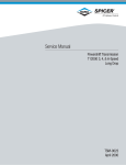
®
Service Manual
DL07
Hydraulic Drill
DANGER
SERIOUS INJURY OR DEATH COULD RESULT
FROMTHEIMPROPERREPAIRORSERVICEOF
THISTOOL.
Copyright©2002TheStanleyWorks
USA&CEVersion
607897/2003 Ver. 1
REPAIRS AND/OR SERVICE TO THIS TOOL
MUSTONLYBEDONEBYANAUTHORIZEDAND
CERTIFIEDDEALER.
Table of Contents
DL07
Hydraulic Drill
SERVICING THE
DL07HYDRAULIC DRILL:
ThismanualcontainsSafety,
Operation,andTroubleshooting
information.Stanley HydraulicTools
recommends that servicingof
hydraulictools,otherthanroutine
maintenance, mustbeperformedby
an authorized andcertifieddealer.
PleasereadtheDANGERwarning
on thecoverandtheSAFETY
warningbelow.
CertificateofConformity
3
Specifications
4
TorqueandDrillSpeeds
4
General SafetyInstructions
5
Tool DecalsandTags
6
HydraulicHoseRequirements
7
HTMARequirements
8
Operating Instructions
9
Service Instructions
12
Troubleshooting
15
Parts Illustration
17
Parts List
18
Accessories
20
Warranty
21
SAFETY FIRST
Copyright c 2003TheStanleyWorks
Allrightsreserved.
Undercopyrightlaw,thisdocumentmay
notbecopiedinwholeorinpartwithout
thepriorwrittenconsentofTheStanley
Works. This exception does not permit
copiestobemadeforothers,whetheror
notsold.Underthelaw,copyingincludes
translatingintoanotherlanguage,format
or medium. This copyright notice must
appearonanypermittedcopies.
It is the responsibility of the operator and
service technician to read rules and
instructions for safe and proper operation
andmaintenance.
A cautious worker using common sense is
thegreatestsafetydevice.
2
Certificate of Conformity
CERTIFICATE OFCONFORMITY
ÜBEREINSTIMMUNGS-ZERTIFIKAT
CERTIFICATDECONFORMITECEE
D’UNMARTEAU-PIQUEUROU D’UNBRISE-BETONEXAMINE
CERTIFICADODECONFORMIDAD
CERTIFICATODICONFORMITA
I,theundersigned:
Ich,derUnterzeichnende:
Jesoussigné:
Elabajofirmante:
losottoscritto:
HydraulicTools
Burrows, James
SurnameandFirstnames/FamiliennnameundVemamen/Nometprénoms/Nombreyapellido/Cognomeenome
herebycertifythattheconstructionplantorequipmentspecifiedhereunder:
bestätigthiermit,daßdieKonstruktionundAusrüstungwie folgtspezifiziertist:
attestequelebrise-béton:
porelpresentecertificoquelafabricaoelequipoespecificadoacontinuacion:
certificochel’impiantool’attrezzaturasottospecificata:
1.
Category: Drill
Kategorie:
Catégorie:
Categoria:
Categoria:
2.
Make/Ausführung/Marque/Marca/Fabbricazion: Stanley
3.
Type/Typ/Type/Tipo/Tipo:DL0755001
4.
Type serialnumberofequipment:
TypundSerien-Nr.derAusrüstung:
Numérodanslasériedutypedematériel:
Numerodeserietipodelequipo:
Matricoladell´attrezzatura:
5.
Year ofmanufacture/Baujahr/annéedefabrication/Añodefabricacion/Annodifabbricazione: 2003
ALL
hasbeenmanufacturedinconformity with-EECTypeexaminationasshown.
wurdehergestelltinÜbereinstimmungmit-EECTyp-Prüfungnach.
estfabriquéconformément -au(x)type(s)examiné(s)commeindiqué dansletableaudi-après.
hasidofabricadodeacuerdocon-tipoexamenEECcomodice.
èstatacostruitainconformitácon-lenormeCEEcomeillustrato.
Directive
Richtlinie
Directivesparticulières
Directriz
Direttiva
No.
Nr
Numéro
No
n.
Date
Datum
Date
Fecha
Data
Approvedbody
Prüfungdurch
Organismeagréé
Aprobado
Collaudato
Dateofexpiry
Ablaufdatum
Dated´expiration
Fechadecaducidad
Datadiscadenza
EN
ENISO
EN
792-3
3744
28662-1
1994
1995
1988
Self
Self
Self
NA
NA
NA
6.
SpecialProvisions: None
SpezielleBestimmungen:
Dispositionsparticulières:
Provisionesespeciales:
Misurespecial:
SoundLevel:
<80dBA
VibrationLevel: 1.2m/s2
Doneat/Ort/Faità/Dadoen/Fattoa StanleyHydraulicTools,Milwaukie,Oregon USA
Signature/Unterschrift/Signature/Firma/Firma
Position/Position/Fonction/Puesto/Posizione EngineeringManager
3
Date/Datum/le/Fecha/Data 7/23/03
Specifications
DriveSize______1/2in./1.3cm3-JawAdjustable
5/8 - 16THDChuck
PressureRange______1000-2000psi/70-140bar
FlowRange_____________4-12 gpm/15-45lpm
OptimumFlow________________8gpm/30lpm
System Type__openorclosedcenter,HTMATYPEI-III
Porting_______________________-8SAEO-ring
ConnectSize&Type___3/8 in.NPTMaleAdapter
Weight_______________________8lbs./3.6kg
OverallLength__________________9 in./23cm
Width_______________________3-1/2 in./9cm
Motor____________________________ Integral
DrillTorque___20ftlbs/27Nmat2000psi/140bar
DrillSpeed__________1000rpmat8gpm/30lpm
RPM Range______________________350-1500
Max. Fluid Temp._____________ 140° F / 60° C
HTMAClass II___________7-9 gpm @ 2000 psi
EHTMACategory_____30 lpm @ 138 bar
Sound Power Level________________87.6 dBA
2
Vibration Level__________________ 0.9 m/s
30Lpmat138bar
BHTMACATEGORY
Torque and Drill Speeds
TORQUE
(Proportionalto oilpressure)
USA
4ftlbs@500psi
9ftlbs@1000psi
14ftlbs@1500psi
19ftlbs@2000psi
DRILLSPEED
(Proportional tooilflow)
METRIC
0.5Nm@35bar
1.2Nm@70bar
1.9Nm@105bar
2.6Nm@140bar
HYDRAULICFLOW
3gpm(11.3lpm)
4gpm(15lpm)
6gpm(23lpm)
8gpm(30lpm)
10gpm(38lpm)
4
DRILLSPEED
350 rpm
475 rpm
750 rpm
1000 rpm
1250 rpm
General Safety Instructions
Alwaysobservesafetysymbols.They areincluded for your safety andtheprotection ofthetool.
DANGER
Thissafetysymbolmayappearon
thetool.Itisusedtoalertthe
operatorof anactionthatcould
placehim/herorothersinalife
threateningsituation.
WARNING
Thissafetysymbolappearsinthese
instructionstoidentifyanaction
thatcouldcausebodilyinjurytothe
operatororotherpersonnel.
CAUTION
This safetysymbolappearsinthese
instructions to identify an action or
condition that could result in
damage to the tool or other
equipment.
This toolwillprovidesafeanddependableserviceifoperatedinaccordancewiththeinstructions
given in thismanual.Readandunderstandthismanualandanystickersandtagsattachedtothe
tool and hoses before operation. Failure to do so could result in personal injury or equipment
damage.
h
Operatormuststartinaworkareawithoutbystanders.Theoperatormustbefamiliarwithallprohibited
workareassuchasexcessiveslopesanddangerousterrainconditions.
h
Establishatrainingprogramforalloperatorstoensuresafeoperations.
h
Donotoperatethetoolunlessthoroughlytrainedorunderthesupervisionofaninstructor.
h
Alwayswearsafetyequipmentsuchasgoggles,headprotection,andsafetyshoesatalltimeswhen
operatingthe tool.
h
Donotinspectorcleanthetoolwhilethehydraulicpowersourceisconnected.Accidentalengagementof
the toolcancauseseriousinjury.
h
DonotoperatethistoolwithoutfirstreadingtheOperatingInstructions.
h
Donotinstallorremovethistoolwhilethehydraulicpowersourceisconnected.Accidentalengagement
of thetoolcancauseseriousinjury.
h
Neveroperatethetoolifyoucannotbesurethatundergroundutilitiesarenotpresent.Underground
electricalutilitiespresentanelectrocutionhazard.Undergroundgasutilitiespresentanexplosionhazard.
Otherundergroundutilitiesmaypresentotherhazards.
h
Donotoperateinapotentiallyexplosiveatmosphere.
h
Donotwearloosefittingclothingwhenoperatingthetool.Loosefittingclothingcangetentangledwith
the toolandcauseseriousinjury.
h
Supplyhosesmusthaveaminimumworkingpressureratingof2500psi/175bar.
h
Besureallhoseconnectionsaretight.
h
Thehydraulic circuitcontrolvalvemustbeinthe“OFF”positionwhencouplingoruncouplingthetool.
Wipeallcouplerscleanbeforeconnecting.Failuretodosomayresultindamagetothequickcouplers
andcauseoverheating. Useonlylint-freecloths.
h
Donotoperatethetoolatoiltemperaturesabove140° F/60 ° C.Operationathigheroiltemperaturescan
causeoperatordiscomfortandmaycausedamagetothetool.
h
Donotoperateadamaged,improperlyadjusted,orincompletelyassembledtool.
h
To avoidpersonalinjuryorequipmentdamage,alltoolrepair,maintenanceandservicemustonlybe
performedbyauthorizedandproperlytrainedpersonnel.
h
Donotexceedtheratedlimitsofthetoolorusethetoolforapplicationsbeyonditsdesigncapacity.
h
Alwayskeepcriticaltoolmarkings,suchaslabelsandwarningstickerslegible.
5
Tool Decals & Tags
ANameTagStickerisattachedtothetool.Neverexceedtheflowandpressurelevelsspecifiedon
thissticker.Theinformationlistedonthenametagstickermustbelegibleatalltimes.Replacethis
sticker if it becomes worn or damaged. A replacement is available from your local Stanley
distributor.
11207
CircuitType“D” Decal
28788
Manual Sticker
30Lpmat138bar
BHTMACATEGORY
29149
Rotation Direction Sticker
WARNING
28323
“CE”Decal
Correctlyconnecthosestotoolports.Donotexceedspecifiedflowor
pressure.Improperhandling,useormaintenancecancausealeakor
burstthatcanresultinoilinjectiontothebody.Failuretoobservethese
precautionsmayresultinseriouspersonalinjury.
58862
Pressure Warning
Sticker
WARNING
ReadownersmanualandensurethatyouPhavebeen
properlytrainedtoworkonorParoundelectriclines.Failureto
usehydraulicPhoselabeledandcertifiedas
non-conductivePmayresultindeathorseriouspersonalinjury.
®
ModelNo.
Dl07
StanleyHydraulicTools
3810SENaefRd
Milwaukie,Oregon97267
58864
Electrical Warning Sticker
15-45lpm/4-12gpm
140bar/2000psi
60807
DL07 Model Sticker
OC/CC
FORUSEONOPENCENTERANDCLOSED
CENTERHYDRAULICSYSTEMS,"SETFOR
PROPERSYSTEMBEFOREUSE"
RATEDNO-LOADSPEED
1000RPMAT
8GPM/30LPM
11354
OC/CC Sticker
29148
RPM Sticker
DANGER
DANGER
1. F A I L U R E T O U S E H Y D R A U L I C H O S E L A B E L E D A N D
CERTI-FIEDASNON-CONDUCTIVE WHENUSING
HYDRAULICTOOLSONORNEARELECTRICALLINES
MAYRESULTINDEATHORSERIOUSINJURY.
BEFOREUSINGHOSE LABELEDANDCERTIFIEDAS
NON-CONDUCTIVE O N O R N E A R E L E C T R I C L I N E S .
BESURETHEHOSEIS MAINTAINEDASNON- CONDUCTIVE . T H E
HOSESHOULDBEREGULARLYTESTEDFORELECTRICCURRENT
LEAKAGEINACCORDANCEWITHYOURSAFETYDEPARTMENT
INSTRUCTIONS.
2. A H Y D R A U L I C L E A K O R B U R S T M A Y C A U S E O I L
INJECTIONINTOTHEBODYORCAUSEOTHERSEVEREPERSONAL
INJURY.
A . D O N O T E X C E E D S P E C I F I E D F L O W A N D
PRESSURE F O R T H I S T O O L . E X C E S S F L O W O R
PRESSUREMAYCAUSEALEAKORBURST.
B.DONOTEXCEEDRATEDWORKINGPRESSURE
OF H Y D R A U L I C H O S E U S E D W I T H T H I S TO O L .
EXCESSPRESSUREMAYCAUSEALEAKOR
BURST.
C . C H E C K T O O L , H O S E , C O U P L E R S &
C O N N E C T O R S
D A I L Y
F O R
L E A K S . D O N O T F E E L F O R L E A K S W I T H
YOURHANDS.CONTACTWITHALEAKMAY
RESULTINSEVEREPERSONALINJURY.
* Not allstickersarefurnishedonalltoolmodels.
Consultpartslistandmodelnumberfordetails.
TheSAFETYTAG,P/N15875,shownatright,smaller
thanactualsize,isattachedtothetoolwhenshipped
from the factory. Read and understand the safety
instructions listed on this tag before removal. We
suggest you retain this tag andattach it to the tool
whennotinuse.
6
(517)
D.DONOTLIFTORCARRYTOOLBYTHEHOSES.DONOTABUSE
HOSE.DONOTUSEKINKED,TORNORDAMAGEDHOSES.
3. M A K E S U R E H Y D R A U L I C H O S E S A R E P R O P E R L Y
CONN-ECTEDTOTHETOOLBEFOREPRESSURIZING
SYSTEM.SYSTEMPRESSUREHOSEMUSTALWAYS
BECONNECTEDTOTOOL“IN”PORT.SYSTEM
RETURNHOSEMUSTALWAYSBECONNECTEDAT
TOOL“OUT”PORT.REVERSINGCONNECTIONSMAY
CAUSEREVERSETOOLOPERATIONWHICHCAN
CAUSESEVEREPERSONALINJURY.
4. D O N O T C O N N E C T C L O S E D - C E N T E R T O O L S T O
O P E N - C E N T E R H Y D R A U L I C SYSTEMS. T H I S M A Y
CAUSEEXTREMESYSTEMHEATAND/ORSEVERE
PERSONALINJURY.
DONOTCONNECTOPEN-CENTERTOOLSTO C L O S E D - C E N T E R
HYDRAULICSYSTEMS.THISMAYRESULTINLOSSOFOTHER
HYDRAULICFUNCTIONSPOWEREDBYTHESAMESYSTEMAND/OR
SEVEREPERSONALINJURY.
5. B Y S T A N D E R S M A Y B E I N J U R E D I N Y O U R W O R K
AREA. K E E P B Y S T A N D E R S C L E A R O F Y O U R W O R K
AREA.
6.WEARHEARING,EYE,FOOT,HANDANDHEADPROTECTION.
7.TOAVOIDPERSONALINJURYOREQUIPMENTDAMAGE,ALLTOOL
REPAIR,MAINTENANCEAND
SERVICEMUSTBE
PERFORMEDBYAUTHORIZED
AND PROPERLY
TRAINEDPERSONNEL.
IMPORTANT
IMPORTANT
READOPERATIONMANUALAND
SAFETYINSTRUCTIONSFORTHIS
TOOLBEFOREUSINGIT.
READOPERATIONMANUALAND
SAFETYINSTRUCTIONSFORTHIS
TOOLBEFOREUSINGIT.
USEONLYPARTSANDREPAIR
PROCEDURESAPPROVEDBY
STANLEYANDDESCRIBEDINTHE
OPERATIONMANUAL.
USEONLYPARTSANDREPAIR
PROCEDURESAPPROVEDBY
STANLEYANDDESCRIBEDINTHE
OPERATIONMANUAL.
TAGTOBEREMOVEDONLYBYTOOL
OPERATOR.
TAGTOBEREMOVEDONLYBYTOOL
OPERATOR.
SEEOTHERSIDE
15875
(517)
SEEOTHERSIDE
15875
Hydraulic Hose Requirements
HOSETYPES
HydraulichosetypesauthorizedforusewithStanleyHydraulicToolsareasfollows:
Certifiednon-conductive
Wire-braided(conductive)
Fabric-braided(notcertifiedorlabelednon-conductive)
Hose listedaboveistheonlyhoseauthorizedforusenearelectricalconductors.
Hoses and listedaboveare conductive and mustnever benearelectricalconductors.
HOSESAFETYTAGS
Tohelpensureyour safety,thefollowingDANGERtagsareattachedtoallhosespurchasedfromStanley
HydraulicTools.DONOTREMOVETHESETAGS.
Iftheinformationinatagisillegible becauseofwearordamage,replacethetagimmediately.Anewtag
maybeobtainedatnochargefromyourStanleyDistributor.
This Tag attachedto“CertifiedNon-Conductive” hose.
(shownsmaller thanactualsize) p/n27987
DANGER
DANGER
1. FAILURETOUSEHYDRAULICHOSELABELEDANDCERTIFIEDASNON-CONDUCTIVEWHENUSING
HYDRAULICTOOLSONORNEARELECTRICLINESMAYRESULTINDEATHORSERIOUSINJURY.
FORPROPERANDSAFEOPERATION,MAKESURETHATYOUHAVEBEENPROPERLYTRAINEDIN
CORRECTPROCEDURESREQUIREDFORWORKONORAROUNDELECTRICLINES.
4. HANDLEANDROUTEHOSECAREFULLYTOAVOIDKINKING,ABRASION,CUTTINGORCONTACT
WITHHIGHTEMPERATURESURFACES. DONOT USEIFKINKED. DONOT USEHOSETOPULLOR
LIFTTOOLS,POWERUNITS,ETC.
5. CHECKENTIREHOSEFORCUTS,CRACKS,LEAKS,ABRASIONS,BULGESORDAMAGETO
COUPLINGS.IFANYOFTHESECONDITIONSEXIST,REPLACETHEHOSEIMMEDIATELY.
NEVERUSETAPEORANYDEVICETOATTEMPTTOMENDTHEHOSE.
2. BEFOREUSINGHYDRAULICHOSELABELEDANDCERTIFIEDASNON-CONDUCTIVEONORNEAR
ELECTRICLINES,WIPETHEENTIRELENGTHOFTHEHOSEANDFITTINGSWITHACLEAN,
DRY,ABSORBENTCLOTHTOREMOVEDIRTANDMOISTUREANDTESTHOSEFORMAXIMUM
ALLOWABLECURRENTLEAKAGEINACCORDANCEWITHSAFETYDEPARTMENTINSTRUCTIONS.
6.
AFTEREACHUSE,STOREINACLEAN,DRYAREA.
3. DONOTEXCEEDHOSEWORKINGPRESSUREORABUSEHOSE.IMPROPERUSEORHANDLINGOF
HOSECOULDRESULTINBURSTOROTHERHOSEFAILURE.KEEPHOSEASFARAWAYAS
POSSIBLEFROMBODYANDDONOTPERMITDIRECTCONTACTDURINGUSE.CONTACTATTHE
BURSTCANCAUSEBODILYINJECTIONANDSEVEREPERSONALINJURY.
SEEOTHERSIDE
SEEOTHERSIDE
Side 1
Side 2
This Tag attachedto“Conductive” hose.
(shownsmaller thanactualsize) p/n29144
DANGER
DANGER
1. DONOTUSETHISHYDRAULICHOSEONORNEARELECTRICLINES.THISHOSEISNOT
LABELEDORCERTIFIEDASNON-CONDUCTIVE.USINGTHISHOSEONORNEARELECTRICLINES
MAYRESULTINDEATHORSERIOUSINJURY.
5. CHECKENTIREHOSEFORCUTS,CRACKS,LEAKS,ABRASIONS,BULGESORDAMAGETO
COUPLINGS.IFANYOFTHESECONDITIONSEXIST,REPLACETHEHOSEIMMEDIATELY.
NEVERUSETAPEORANYDEVICETOATTEMPTTOMENDTHEHOSE.
2. FORPROPERANDSAFEOPERATION,MAKESURETHATYOUHAVEBEENPROPERLYTRAINEDIN
CORRECTPROCEDURESREQUIREDFORWORKONORAROUNDELECTRICLINES.
6.
AFTEREACHUSE,STOREINACLEAN,DRYAREA.
3. DONOTEXCEEDHOSEWORKINGPRESSUREORABUSEHOSE.IMPROPERUSEORHANDLINGOF
HOSECOULDRESULTINBURSTOROTHERHOSEFAILURE.KEEPHOSEASFARAWAYAS
POSSIBLEFROMBODYANDDONOTPERMITCONTACTDURINGUSE.CONTACTATTHE
BURSTCANCAUSEBODILYINJECTIONANDSEVEREPERSONALINJURY.
4. HANDLEANDROUTEHOSECAREFULLYTOAVOIDKINKING,ABRASION,CUTTINGORCONTACT
WITHHIGHTEMPERATURESURFACES. DONOT USEIFKINKED. DONOT USEHOSETOPULLOR
LIFTTOOLS,POWERUNITS,ETC.
SEEOTHERSIDE
SEEOTHERSIDE
Side 1
Side 2
HOSEPRESSURERATING
Theratedworkingpressureofthehydraulichosemustbeequaltoorhigherthanthereliefvalvesettingon
thehydraulicsystem.
7
HTMA Requirements
Tool Category
C
Hydraulic System
Requirements
Flowrate
ToolOperatingPressure
20Lpmat138bar
BHTMACATEGORY
Type I
30Lpmat138bar
BHTMACATEGORY
40Lpmat138bar
EHTMACATEGORY
Type III
Type II
4-6 gpm
7-9gpm
10.5-11.6gpm
(15-23lpm)
(26-34lpm)
(36-44lpm)
(42-49lpm)
2000psi
2000psi
2000psi
2000psi
(138bar)
(138bar)
(138bar)
(138bar)
Systemreliefvalvesetting
2100-2250psi
2100-2250psi
2100-2250psi
2100-2250psi
(atthepowersupplyoutlet)
(145-155bar)
(145-155bar)
(145-155bar)
(145-155bar)
Maximumbackpressure
200psi
200psi
200psi
200 psi
(attoolendofthereturnhose)
(14bar)
(14bar)
(14bar)
(14bar)
Measuredatamax.fluidviscosityof:
400ssu*
400ssu*
400ssu*
400 ssu*
(atmin.operatingtemperature)
(82centistokes)
(82centistokes)
(82centistokes)
(82centistokes)
Temperature
Sufficientheatrejectioncapacity
tolimitmax.fluidtemperature to:
140° F (60°C)
140° F (60°C)
140° F (60°C)
140 ° F (60°C)
3 h p (2.24kW)
40 ° F (22°C)
5 h p (3.73kW)
40 ° F (22°C)
6 h p (4.47kW)
40 ° F (22°C)
7hp (5.22kW)
40° F (22°C)
25 microns
18 gpm (68lpm)
25microns
30gpm (114lpm)
25microns
35gpm (132lpm)
25microns
40gpm (151lpm)
100-400 ssu*
100-400 ssu*
100-400 ssu*
100-400 ssu*
(20-82centistokes)
(20-82centistokes)
(20-82centistokes)
(20-82centistokes)
(atthepowersupplyoutlet)
11-13 gpm
(atmax.expectedambienttemperature)
Min.coolingcapacity
atatemperaturedifference of
betweenambientandfluidtemps
NOTE: Donotoperatethetoolatoil
temperaturesabove140°F(60°C).Operation
athighertemperaturescancauseoperator
discomfortatthetool.
Filter
Min.full-flow filtration
Sizedforflowofatleast:
(Forcoldtemp.startupandmax.dirt-holding
capacity)
Hydraulicfluid
Petroleumbased
(premiumgrade,anti-wear,non-conductive)
Viscosity
(atmin.andmax.operatingtemps)
NOTE: Whenchoosinghydraulicfluid,the
expectedoiltemperatureextremesthatwillbe
experiencedinservicedeterminethe
mostsuitabletemperatureviscosity
characteristics.Hydraulicfluidswithaviscosity
indexover140willmeettherequirementsover
awiderangeofoperatingtemperatures.
*SSU=SayboltSecondsUniversal
NOTE:Thesearegeneralhydraulicsystemrequirements.Seetool Specificationpagefortoolspecific
requirements.
8
Operating Instructions
NOTE:Ifuncoupledhosesare left inthe sun,
pressure increase inside the hose mayresult
inmakingthemdifficultto connect. Whenever
possible, connectthefreeendsofthehoses
together.
Pre-OperationProcedures
InstallChuck
Screw the chuckontotheoutputshaft.Tightento
50ftlbs/68Nmtorque,lubricated.
Drill Operation
CAUTION
1. Observeallsafetyprecautions.
Usetheflatsontheshafttoholdtheshaftduringtighteningor
looseningofthechuck.
2. Placetheselecteddrillbitfullyintothechuck.
Center thebitandtightenthechuckusingthe
keyprovided.Removethekeyandstoreaway
fromthedrill.
Check Power Source
1. Using a calibratedflowmeterandpressure
gauge, checkthatthehydraulicpowersource
developsaflowof4-12gpm/15-45lpmat
1000-2000psi/70-140bar.
3. Momentarilypressthetrigger to ensurethat
the drillbitrotatesclockwiseandrunstrue.
CAUTION
2. Makecertainthatthehydraulicpowersource
is equippedwithareliefvalvesettoopenat
2100psi/145barmaximum.
Makecertainthatthechuckhasbeensecurelymounted.
4. Selectaworkpositionthatgivessecure
footing andbalancewhileoperatingthedrill.
Connect Hoses
5. Pressthedrillagainsttheworkandsqueeze
the trigger.
1. Wipeallhosecouplers with a cleanlint-free
clothbeforemakingconnections.
Thedrillingmethodusedisdeterminedbythe
materialbeingdrilledandthesizeanddepth
requirements ofthehole.
2. Connecthosesfromthe hydraulicpower
supplytothetoolquickdisconnects.Itisa
goodpracticetoconnectthereturnhosefirst
anddisconnect itlasttominimize oravoid
trappedpressurewithinthedrill.
Brittlematerialsuchasrock,brickorconcretecan
bedrilledefficientlywhenthe bitiscausedto
strike (hammer) theholebottomtobreakupthe
material. Without hammering,therotatingbitwill
onlygrinddownandbecomedull.TheStanley
HD08 shouldbeusedforthisapplication.
3. Observethearrowonhose couplers to ensure
thatthe flow is in the properdirection.The
malecoupleronthecircuithoseendisthe
supply(pressure) coupler.
Ductilematerial such asmetalorwoodisdrilled
efficientlywhenasteadydownforceisappliedto
the drillcentertocausethebittoslicechipsof
materialfrom theholebottom.Whendrillingin
metal,useacuttinglubricanttoprolongbitlife
and reducetheamountofforcerequiredtodrill
effectively.
4. MakesurethecircuitPRESSUREhose(with
malequickdisconnect)isconnectedtothe
port atthebackofthedrillhandle.Thecircuit
RETURN hose(withfemalequickdisconnect)
is connectedtothe portclosest tothetrigger.
5. Movethehydrauliccircuitcontrolvalvetothe
ON positiontodirecthydraulicflowtothe
drill.
Largedrill holesaremoreproductivelycreated
fromsmall drillholes.Drillbits areincrementally
selectedtoenlargetheholeuntilthedesiredhole
sizeis obtained. Eachbitselectedmustalways be
toolargetothreadandjamintoanexistinghole;
9
Operating Instructions
otherwisethebitmaybreakandendangerthe
operator.
Cold Weather Operation
CAUTION
To prevent damagetotheretaining
ring, do not attempt to force the
Ifthetoolistobeusedduringcoldweather,preheat
selector screw counter-clockwise
the hydraulicfluidatlowenginespeed.Whenusing
beyondthepointofinitialresistance.
the normally recommendedfluids,fluid temperature
should be a t o r a b o v e 5 0°F/10°C(400ssu/82
centistokes)beforeuse.
3. Reinstallhexplug.Failuretoinstallplugmay
introducecontaminantstothe spool boreresulting
Damage to thehydraulicsystemortoolcanresult
inreplacementofthevalvespoolandmain
from use withfluidthatistooviscousorthick.
Housing.
Open Center/ Closed Center Setup
(OC/CC)
This toolcanbeconfiguredtorunonbothopencenter
andclosedcentersystems.Setforpropersystem
beforeuse.
1. Determine systemtype.
2. Remove hexplug(81)fromspringcapusinga
3/16in.Hex.
ClosedCenter
Usinga3/16in.Hex,reach
throughthe hole inthespringcap
andturntheselectorscrewfully
clockwise.Whentheselector
screw bottoms,closedcenter
operationisselected.
OpenCenter
Usinga3/16in.Hex,reach
throughthe hole inthespringcap
andturntheselectorscrew
counter-clockwise untilmeeting
resistance(fromtheretaining
ring).Turntheselectorclockwise
andthencounter-clockwisetobe
suretheselectorisbeingstopped
bytheretainingring.Donotforce
theselectorscrew.Opencenter
Operationisnowselected.
9
Service Instructions
Note: For orientation of partsin thefollowing
procedures, refer tothepartsdrawinglaterinthis
manual.
5. Removetheplanetgears(26)fromtheoutputshaft.
Inspectshafts,gearsandgearborebushings(see
CLEANINGANDINSPECTIONprocedure).
Prior to Disassembly
1. Cleantheexteriorofthetoolandplaceonaclean
worksurface.
6. Spintheballbearing(28)ontheoutputshaft.The
bearingshouldturnsmoothly.Toreplacethebearing,
supporttheouterraceandpressdownontheoutput
shaftfromthechuckend.Donotreusetheballbearing
onceithasbeenremovedfromtheoutputshaft.
2. Obtainthe seal kitlistedonthePARTSLISTsoall
sealsexposedduringdisassemblycanbereplaced.
7. Removetheoutputshaftseal(30)bypressingit
fromthegearhousingbore.
Prior to Reassembly
8. Checktheendfacesofthesealnutandoutputshaft
for nicksandwar(seeCLEANINGAND
INSPECTIONprocedure).
1. Cleanallpartswithadegreasingsolution.
2. Blowdryallpartsoruselint-freecloths.
3. Ensurethatallsealsexposedduringdisassembly
are replacedwithnewparts.
4. Applycleangrease oro-ringlubricanttoallparts
duringassembly.
Motor Cap
9. Removethesixcapscrews(41)andlockwashers(3)
securingthemotorcapassembly(46)tothemain
housingassemblyandliftoffthemotorcapassembly.
Donotinanywayexcessivelyforcethemotorcapoff
the mainhousingassembly.
10. Removetheo-ring(9)fromthemotorcap.
MainShaftand Idler Shaft
Tool Disassembly
Gear Housing
1. Removethechuck(33)fromtheoutputshaft(36)by
holdingthesealnut(35)withanopenendwrenchand
turningthe chuckcounter-clockwise.
2. Removethecapscrews(31)andlockwashers(32)
securingthegearhousing(69)tothemainhousing
assembly(76).Ifthetoolhasatriggerguard(80),
remove capscrew(34), nut(20)andtriggerguard
beforeremovingthe gearhousing.
3. Removetheringgear(27),rollpin(5)andgasket
(71).
4. Removetheretainingring(29)neartheplanetshafts
(23)beforeremovingtheplanetshafts.Removethe
sealnut(35)byusingtheplanetshaftholestokeepthe
outputshaftfromturning.Pulltheoutputshaftwith
attachedparts fromthegearhousing.
11. Taponthesmallgearendofthemainshaft(5)
andpushtheshaftfromthemainbody.
12. Removetheidlergear(45)andidlershaft(47).
13. Removetheretainingring(16)andthenpickout
the sealwasher(44),back-upring(39)ando-ring(4)
fromthemainhousing.
Valve Spool
14. Unscrewthespringcap(66),pickoutthespring
(79)andpushthevalvespool(59)outthespringcap
endofthemainhousing.
Trigger
15. Removethetriggerbyfirstremovingthe
capscrews(8)andlockwashers(32)andremovingthe
trigger andtriggermount(78)asanassembly.Drive
outtherollpin(21).
12
Service Instructions
ReversingSpool
16. Removetheretainingrings(67)andendcaps(65).
17. Unscrewthesealcaps(64)andslidethereversing
spool(68)outofthemainhousing.Makesuretheidler
shafthasbeenremovedpriortocompletingthisstep.
Cleaning and Inspection
Cleaning
Cleanallpartswithade-greasingsolution.Blowdry
withcompressedairoruselint-freecloths.
Gear Chamber(MotorCap)
Thechamberboresandbottomsaroundtheshaft
bushingsshouldbepolishedandnotroughorgrooved.
Ifthebushingboresareyellow-bronze,replacethem
andinvestigatethe causeofwear.
Theflatsurfacesaroundthechamberandboltholes
shouldbeflatandfreeofnicksorburrstha t could
causemisalignmentorleaks.
micronfiltertoanoversized10-micronfilter.
Tool Reassembly
1. Lubricateandinstallanewo-ring(4)andback-upring
(39)intothemainhousing.Installthesealback-upwasher
(44)andretainingring(16).
2. Slidethereversingspool(68)intothemainhousing
assembly.Insertthe spoolwiththeslottowardtheidler
shaftholeandthenarrowsideofthedepressioninthe
spoolfacinguptowardthetopofthemainhousing.
3. Inserttheidlershaft(47)topreventthereversingspool
fromturning.
4. Lubricate andinstallanewwiperseal(63),o-ring(10),
back-upring(17)ando-ring(2)intoeachsealcap (64).
Installeachsealcapontothemainhousingassembly.
5. Installeachendcap(65)andsecurewithsnapring(67).
Bushings
Theinsideofthebushingsshouldbegraywithsome
bronze showingthrough.Ifsignificantyellow-bronze
shows,replacethe bushings.Inspectthemotorshaft
andidlershaftforcorrespondingwearandreplaceas
required.
Gears
Thedriveandidlergearsshouldhavestraighttips
withoutnicks, squaretoothendsandhaveasmooth
evenpolishontheteethandendfaces.Replacethe
gear if cracks arepresent.
6. Lubricatesealareaofmainshaft(50)andinstallitinto
the mainhousing.Installtheidlergear(45)ontotheidler
shaft.
7. Lubricateandinstallanewo-ring(9)ontothemotor
cap(46).Lubricate capscrewthreads(41)withanantiseizecompoundandinstallthemotorcapwiththe
capscrewsandlockwashers(3).Tightenboltsto15-17ft
lbs / 20-23Nminacrosspattern.
CAUTION
Donotforcepartstogether.
MainHousingAssembly
Thesurfacenearthegearsshouldshowtwo
interconnectingpolishedcircleswithoutastep.
Shafts
Theshaftdiameteratthebearingandseallocations
mustbesmooth.Grooves,roughnessorareduced
diameter indicatefluidcontaminationordamaged
bushings.Gritparticlesmayhavebeenimbeddedin
the bushings,grindingintothe hardenedshaft. If
abnormalshaftwearasnotedaboveoccurs(morethan
normalpolishing),replaceboththeshaftand
associatedbushings.
Alsocheckthehydraulicsystemforexcess
contaminationinthefluidandforfiltercondition.
Operatingconditionsmayrequirechangingfroma25-
13
8. Lubricateandinstallanewo-ring(19)inthemain
housingandanewsealwiper(61)inthetriggermount
(78). Securethetrigger(77)totriggermountwithrollpin
(21). Installtriggerassemblytomainhousingwith
capscrews(8)andlockwashers(32).
9. Lubricateandinstallanewo-ring(18)onthevalve
spool(59)beforeinstallingvalvespoolintothemain
housingfromthespringcapend.Donotinstallthevavle
spoolfromthetriggersideofthemainhousingasthiswill
resultinspoolsealdamage.Ensurethatthetabonthe
valvespoolnoseisalignedwiththeslotinthetrigger.
Installspring(79)behindvalvespool.UsingLoctite™
242,installthespringcap(66)tothemainhousing.
10. Lubricate andinstalltheshaftseal(30)intothegear
Service Instructions
housing. Installshaftkeeper(24)andbearing
keeper(25)beofreinstallingbearing(28)on
outputshaft(36).Installplanetgears(26)into
outputshaftandinstalltheoutputshaftwith
aqttachedpartsintothegearhousing(69).Install
the ringgear(27)intothegearhousingandsecure
withtherollpin(5).Installthesealgasket(71)
aroundtheringgear.
11. Lubricateandinstalltheo-ring(4)onthe
outputshaft.Installthesealnut(35),usingthe
planetshaftborestopreventtheoutputshaftfrom
turning. Installtheplanetshafts(23)andsecure
themwithretainingring(29).In stallthegear
chamberandattachedpartstothemainhousing
usingcapscrews(31)andlockswashers(32).If
the tool hasatriggerguard(80),installguardwith
capscrew(34)andnut(20)atthistime.
12. Lubricate theoutputshaftthreadsandinstall
the chuck(33).Whileholdingthesealnutsecure
withanopenendwrench,torquethechuckto50
ftlbs / 69Nm.
14
Troubleshooting
Thissectiondescribeshowtofindandresolveproblemsusersmayexperience.Ifasituationoccursthatisnotcovered,
callyourStanleyCustomerServicerepresentativeforassistance.
WARNING
Inspectingthetoolorinstallingpartswiththehydraulichosesconnectedcanresultinseverepersonalinjuryoreq uipment
damage.
Topreventaccidentalstartup, disconnectthehydraulicpowerbeforebeginninganyinspectionorinstallationtask.
Ifsymptomsofpoorperformancedevelop,thefollowingchartcanbeusedasaguidetocorrecttheproblem.
Whendiagnosingfaultsinoperationofthetool,alwayscheckthatthehydraulicpowersourceissupplyingthecorrect
hydraulicflowandpressuretothetoolaslistedinthetable.Useaflowmeterknowntobeaccurate.Checktheflow
withthehydraulicoiltemperatureatleast80°F/27°C.
Symptom
Tool will not start.
Possible Cause
Power notbeingsupplied.
Defectivequick disconnects.
Low drilling
torque.
Solution
Check to make certainthatboth
hosesare connected.
Turn hydrauliccircuitcontrolvalve
ON.
Check eachquick disconnect
separately. Replaceasnecessary.
Relief valvesetting toolow.
Setreliefvalveat2100psi/145bar.
Fluid restriction in hoseorvalve.
Excessflowandpressure loss.
Locateandremoverestriction.
Usecorrectfluid.
Fluidnotwarmed-up.Preheat
system.
Hoses toolongforhoseI.D.Use
shorter hose.
Hoses I.D.toosmallforhose
length.Uselarger I.D. hose.
Low tool speed.
Fluidflowrateistoolow.
Check circuit flow rate.
Tool speed too
high.
Fluidflowrateisexcessive.
Check circuit flow rate; add a
proper flow control valveorreduce
the pumpRPM.
Oilleaks around
gearhousing.
Hydraulicpressure andreturn
hosesreversed.
Correct hose connections. Pressure
should be to thehandle port away
fromthetrigger,return is near the
trigger;thenreplace themain shaft
oil seal.
Main shaft seal o-ringleaking.
Replace seal;check seal contact
surfaces.
continued
15
Troubleshooting
Symptom
Oil getshot,
power unit
working hard.
Possible Cause
Solution
Open center tool onaclosedcenter Usetoolstomatchcircuit.
circuit andviceversa.
Circuit relief set toolow.
Adjust relief valve to 2100 psi/ 145
bar.
Toomuch oil goingthrough tool.
Adjust flow for 12gpm/45lpm
maximum, or less.
Oilleaks at
reversing spool.
Damaged o-rings.
Replaceasrequired.
Wronghydraulic fluid. Circuit too
hot.
SeeOPERATINGINSTRUCTIONS
for correctfluid/ circuit
specifications.
Oilleakatmotor
capface.
Fasteners loose.
Refer toSERVICEMANUAL
Faceo-ringwornormissing.
Replaceasrequired.
Motorcap/ mainhousing damaged. Replaceasrequired.
16
DL07 Parts Illustration
17
DL07 Parts List
Item
1
2
3
4
5
6
7
8
9
10
11
12
13
14
15
16
17
18
19
20
21
22
23
24
25
26
27
28
29
30
31
32
33
34
35
36
37
38
39
40
41
42
43
44
45
46
47
48
49
50
51
52
53
54
55
56
57
58
59
60
61
62
63
64
Part
Qty.
00026
00175
00231
00354
00563
00713
00717
00803
01262
01604
02324
03288
03364
05206
05207
06635
07224
07626
07627
07724
07970
08130
08161
08162
08163
08165
08166
08175
08440
09621
09622
09623
09624
27628
09687
09778
09779
11207
11354
13995
16070
18206
20758
20760
27067
20769
20770
20782
24058
24059
24271
25610
28323
60807
28788
29148
29149
38676
38685
48987
48989
49139
56725
56747
56749
2
2
6
2
1
2
1
2
1
1
1
1
1
2
2
1
2
1
1
1
1
1
2
1
1
2
1
1
1
1
3
5
1
1
1
1
1
1
1
1
1
6
1
1
1
1
1
1
1
1
1
1
2
1
2
1
1
1
1
1
1
1
2
2
2
Notes
Description
O-ring3/16x5/16x1/16-008
O-ring1/2x5/8x1/16-014
Lockwasher5/16"I.D
O-ring1/2x11/16x3/32-112
RollPin3/16O.D.x.375LG.
DowelPin1/4x1
O-ring1/4x3/8x1/16-010
HSHCS10-24x5/8
O-ring1-3/4x1-7/8x1/16-031
O-ring.755x.949x.097-910
Cap&Plug½in.
Cap&Plug3/8in.
O-ring.441x.558x.072-905
Bushing
Bushing
RetainingRing
BackupRing-014
O-ring1/2x5/8x1/16-014
O-ring5/8x3/4x1/16-016
NylockNut10-24unc
RollPin3/16O.d.x1.375LG.
Handle
PlanetShaft
ShaftKeeper
BearingKeeper
PlanetGearAssembly
RingGear
BallBearing
RetainingRing
ShaftSeal
HSHCS10-24x1-1/4
Lockwasher#10
½in.DrillChuck
5/8in.DrillChuck
HSHCS10-24x2.000
SealNut
OutputShaft
Circuittype“D”Sticker
OC/CCSticker
Back-upRing-112
RetainingRing
HSHCS5/16-18x1-3/4
Bushing
Bushing
SealBack-upWasher
IdlerGearAssembly
MotorCapAssembly
IdlerShaft
3/8in.Flush-faceCouplerBody3/8npt
3/8in.Flush-faceCouplerNose3/8npt
MainShaft
RailroadHelpDeskSticker
Sticker“CE”12mm
DL07ModelNo.Sticker
Sticker-Manual
RPMSticker
RotationDirectionSticker
DepthGageRod
ThumbScrew10-32UNFx.375
ValveSpool
SelectorScrew
SealWiper
HoseAssy471ST-05-01-08-06-08-18
SealWiper
SealCap
18
ModelDL07552SUPOnly
ModelDL07552SUPOnly
ModelsDL07652,552S,552SUP,572SOnly
IncludesItem#14
ModelsDL07550,5001,652,552S,552SUPOnly
ModelDL07572SOnly
ModelDL0755001Only
IncludesItem#43
IncludesItem#6and15
PartofSet24069-ModelsDL07552S,552SUP,572S Only
PartofSet54069-ModelsDL07552S,552SUP,572SOnly
ModelsDL07552S,552SUP,572SOnly
ModelDL0755001Only
ModelDL0755001Only
ModelDL0755001Only
ModelsDL07552S,572SOnly
ModelsDL07552S,572SOnly
ModelsDL07552S,552SUP,572SOnly
DL07 Parts List
Item Part Qty.
65
66
67
68
69
70
71
72
73
74
75
76
77
78
79
80
81
56757
56758
56764
56765
58403
58462
58635
58856
58857
58862
58864
59049
60677
60678
60679
60710
350041
2
1
2
1
1
1
1
1
1
1
1
1
1
1
1
1
1
Notes
Description
EndCap
SpringCap
RetainingRing
ReversingSpool
GearHousingMachining
ReliefCartridgePlugAssembly
IncludesItems#7and13
SealGasket
3/8in.Flush-faceCouplerBody-8(½)MaleSAE PartofSet58718-ModelsDL07550,55001,652Only
3/8in.Flush-faceCouplerNose-8(½)MaleSAEPartofSet58718-ModelsDL07550,55001,652Only
WarningSticker - Pressure
ModelsDL07550,652,552S,552SUP,572SOnly
WarningSticker - Electrical
ModelsDl07550,652,552S,552SUP,572SOnly
MainHousingAssembly
IncludesItems#15and42
TriggerCasting
TriggerMountCasting
Spring
TriggerGuard
HollowHexPlug-4SAE
NOTE:
Use Part Number and
Description whenordering.
SealKitP/N60792
1
2
4
7
9
10
13
17
18
19
30
39
63
65
73
00026
00175
00354
00717
01262
01604
03364
07224
07626
07627
09621
13995
49139
56747
58635
O-ring,3/16x5/16x1/16-008
O-ring,1/2x5/8x1/16-014
O-ring,1/2x11/16x3/32-112
O-ring,1/4x3/8x1/16-010
O-ring,1-3/4x1-7/8x1/16-031
O-ring,.755x.949x.097-910
O-ring,.441x.558x.072-905
Backupring,-014
O-ring,½x5/8x1/16-014
O-ring,5/8x3/4x1/16-016
ShaftSeal
Backupring-112
SealWiper
SealWiper
SealGasket
2
2
2
1
1
2
1
2
1
1
1
1
1
2
1
19
Accessories
NOTE:
Use Part Number
and Description when
ordering.
Part
Description
WoodAugerBits,5/8 in.Hex
27845
27847
9/16in.diax18in.CarbideTippedAugerBit(22in.oal)
13/16in.diax18in.CarbideTippedAugerBit(22in.oal)
WoodAugerBits,7/16in.Hex
27850
27851
27852
27853
27854
27855
27856
27857
27858
27859
27860
27861
27862
27863
27864
27869
32399
32400
9/16in.dia.x8in.CarbideTippedAugerBit(12in.oal)
11/16in.dia.x8in.CarbideTippedAugerBit(12in.oal)
13/16in.dia.x8in.CarbideTippedAugerBit(12in.oal)
15/16in.dia.x8in.CarbideTippedAugerBit(12in.oal)
1-1/16 in.dia.x8in.CarbideTippedAugerBit(12in.oal)
9/16in.dia.x12in.CarbideTippedAugerBit(16in.oal)
11/16in.dia.x12in. CarbideTippedAugerBit(16in.oal)
13/16in.dia.x12in.CarbideTippedAugerBit(16in.oal)
15/16in.dia.x12in.CarbideTippedAugerBit(16in.oal)
1-1/16 in.dia.x12in.CarbideTippedAugerBit(16in.oal)
9/16in.dia.x18in.CarbideTippedAugerBit(22in.oal)
11/16in.dia.x18in.CarbideTippedAugerBit(22in.oal)
13/16in.dia.x18in.CarbideTippedAugerBit(22in.oal)
15/16in.dia.x18in.CarbideTippedAugerBit(22in.oal)
1-1/16 in.dia.x18in.CarbideTippedAugerBit(22in.oal)
13/16in.diax36in.CarbideTippedAugerBit(48in.oal)
11/16in.diax15in.CarbideTipp edAugerBit(18in.oal)
13/16in.diax15in.CarbideTippedAugerBit(18in.oal)
20
Warranty
StanleyHydraulicTools(hereinaftercalled“Stanley”),subjecttotheexceptionscontainedbelow,warrantsnewhydraulictoolsforaperiodofone
yearfromthedateofsaletothefirstretailpurchaser,orforaperiodof2yearsfromtheshippingdatefromStanley,whicheverperiodexpiresfirst,to
befreeofdefectsinmaterialand/orworkmanshipatthetimeofdelivery,andwill,atitsoption,repairorreplacean y t o o l o r p a r t o f a t o o l , o r n e w
part,whichisfounduponexaminationbyaStanleyauthorizedserviceoutletorbyStanley’sfactoryinMilwaukie,OregontobeDEFECTIVEIN
MATERIALAND/ORWORKMANSHIP.
EXCEPTIONSFROMWARRANTY
NEWPARTS: Newpartswhichareobtainedindividuallyarewarranted,subjecttotheexceptionsherein,tobefreeofdefectsinma terialand/or
workmanshipatthetimeofdeliveryandforaperiodof6monthsafterthedateoffirstusage. Sealsanddiaphragmsarewarrantedtobefreeof
defectsinmaterialand/orworkmanshipatthetimeofdeliveryandforaperiodof6monthsafterthedateoffirstusage or2yearsafterthedateof
delivery,whicheverperiodexpiresfirst. Warrantyfornewpartsislimitedtoreplacementofdefectivepartsonly. Laborisnotcovered.
FREIGHTCOSTS: Freightcosts toreturnpartstoStanley,ifrequestedbyStanleyforthepurposeofevaluatingawarrantyclaimforwarrantycredit,
arecoveredunderthispolicyiftheclaimedpartorpartsareapprovedforwarrantycredit. Freightcostsforanypart orpartswhicharenotapproved
forwarrantycreditwillbetheresponsibilityoftheindividual.
SEALS&DIAPHRAGMS: Sealsanddiaphragmsinstalledinnewtoolsarewarrantedtobefreeofdefectsinmaterialand/orworkmanshipfora
periodof6monthsafterthedateoffirstusage,orforaperiodof2yearsfromtheshippingdatefromStanley,whichever periodexpiresfirst.
CUTTINGACCESSORIES: Cuttingaccessoriessuchasbreakertoolbitsarewarrantedtobefreeofdefectsinmaterialandorworkmanshipatthe
timeofdeliveryonly.
ITEMSPRODUCEDBYOTHERMANUFACTURERS: ComponentswhicharenotmanufacturedbyStanleyandarewarrantedbytheirrespective
manufacturers.
a.CostsincurredtoremoveaStanleymanufacturedcomponentinordertoserviceanitemmanufacturedbyother
manufacturers.
ALTERATIONS&MODIFICATIONS: Alterationsormodificationstoanytoolorpart. Allobligationsunderthiswarrantyshallbeterminatedifthe
newtoolorpartisalteredormodifiedinanyway.
NORMALWEAR: Anyfailureorperformancedeficiencyattributabletonormalwearandtearsuchastoolbushings,retainingpins,wearplates,
bumpers,retainingringsandplugs,rubberbushings,recoilsprings,etc.
INCIDENTAL/CONSEQUENTIALDAMAGES: Tothefullestextentpermittedbyapplicablelaw,innoeventwillSTANLEYbeliableforany
incidental,consequentialorspecialdamagesand/orexpenses.
FREIGHTDAMAGE: Damagecausedbyimproperstorageorfreighthandling.
LOSSTIME: Lossofoperatingtimetotheuserwhilethetool(s)isoutofservice.
IMPROPEROPERATION: Anyfailureorperformancedeficiencyattributabletoafailuretofollowtheguidelinesand/orproceduresasoutlinedin
thetool’soperationandmaintenancemanual.
MAINTENANCE: Anyfailureorperformancedeficiencyattributabletonotmaintainingthetool(s)ingoodoperatingconditionasoutlinedinthe
OperationandMaintenanceManual.
HYDRAULICPRESSURE&FLOW,HEAT,TYPEOFFLUID: Anyfailureorperformancedeficiencyattributabletoexcesshydraulicpressure,
excesshydraulicback-pressure,excesshydraulicflow,excessiveheat,orincorrecthydraulicfluid.
REPAIRSORALTERATIONS: AnyfailureorperformancedeficiencyattributabletorepairsbyanyonewhichinStanley’ssolejudgementcausedor
contributedtothefailureordeficiency.
MIS-APPLICATION: Anyfailureorperformancedeficiencyattributabletomis-application.“Mis -application”isdefinedasusageofproductsfor
whichtheywerenotoriginallyintendedorusageofproductsinsuchamatterwhichexposesthemtoabuseoraccident,withoutfirstobtainingthe
writtenconsentofStanley. PERMISSIONTOAPPLYANYPRODUCTFORWHICHITWASNOTORIGINALLYINTENDEDCANONLYBE
OBTAINEDFROMSTANLEYENGINEERING.
WARRANTYREGISTRATION: STANLEYASSUMESNOLIABILITYFORWARRANTYCLAIMSSUBMITTEDFORWHICHNOTOOLREGISTRATIONISONRECORD. Intheeventawarrantyclaimissubmittedandnotoolregistrationisonrecord,nowarrantycreditwillbeissuedwithoutfirst
receivingdocumentationwhichprovesthesaleofthetoolorthetools’firstdateofusage. Theterm“DOCUMENTATION”asusedinthisparagraph
isdefinedasabillofsale,orletterofintentfromthefirstretailcustomer. A WARRANTYREGISTRATIONFORMTHATISNOTALSOON
RECORDWITHSTANLEYWILLNOTBEACCEPTEDAS“DOCUMENTATION”.
NOADDITIONALWARRANTIESORREPRESENTATIONS
ThislimitedwarrantyandtheobligationofStanleythereunderisinlieuofallotherwarranties,expressedorimpliedincludingmerchantabilityor
fitnessforaparticularpurposeexceptforthatprovidedherein. Thereisnootherwarranty. Thiswarrantygivesthe purchaserspecificlegalrights
andotherrightsmaybeavailablewhichmightvarydependinguponapplicablelaw.
21
Foradditional Sales&Service information, contact:
®
StanleyHydraulicTools
Division of the Stanley Works
3810SENaefRoad
Milwaukie, OR 97267 USA
Tel: (503)659-5660
Fax:(503) 652-1780
www.stanley-hydraulic-tools.com