1
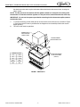
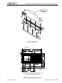
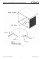
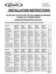
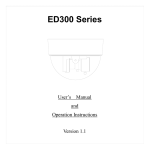
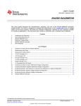
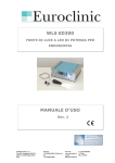
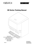
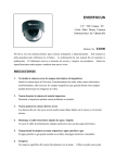
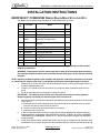
ED/DF300 22” CCM322/522 Nordic Style Lid Kit Installation Instructions
INSTALLATION INSTRUCTIONS
ED/DF300 22” CCM322/522 NORDIC BLACK/GRAY STYLE LID KITS
This Nordic style kit applies to the Cornelius 22” wide CCM322/522 ice maker.
Item
No.
Part No.
Name
Qty.
1
15210
Lid Assembly
1
2
22127
Icemaker Mounting Bracket
2
3
50904
RTV. 3Oz Tube
1
1
4
52946
Manual Ice Fill Cover, Black
52964
Manual Ice Fill Cover, Gray
5
91957
Label, “Disconnect Power Before
Cleaning”
1
6
620042919
ED300 Ice Baffle
1
7
620701601
#10 x 1/2” LG. Sheetmetal Screw
8
8
620701902
#8–32 Nylon Acorn Nut
4
9
620701901
Sealing Washer
4
10
621701903
#8 Nylon Washer
4
11
620204725INS Installation Instructions
1
13
630500109
1
Bin Stat
CAUTION: Disconnect electrical power to the dispenser before proceeding with the icemaker
adapter kit installation.
WARNING: The dispenser must be secured with 3/8-16 bolts (6) to the counter before installing
this Icemaker Adapter Kit. Refer to the installation manual and Figure 2 for the counter mounting
template.
NOTE: Adjust the automatic agitation timer located in the dispenser’s electrical control box to 5 seconds
on, 20 minutes off. Access to the timer is provided by removing the merchandiser/upper front panel.
1.
Remove the (2) screws from each side of the dispenser cabinet. and the plastic hopper covers (2)
that were shipped with the unit.
2.
Place the “K” style lid on the unit and use the (4) screws that were removed to fasten the lid in
place.
3.
Install the ice baffle on the lid assembly as shown in Figure 2.
IMPORTANT: The baffle prevents ice from over–filling the manual fill area during agitation/
dispensing with a full storage bin and forcing the manual fill cover off.
4.
5.
6.
Seal the icemaker to the top of the dispenser after determining the correct location for the ice maker
(see Figure 1).
A. Run beads of RTV around the opening in the lid and inside of the perimeter of the ice maker
outline so that the ice maker will set on the RTV.
B. Set the ice maker onto the lid and position it as required.
C. Wipe away the excess RTV.
5. Drill .147 diameter holes into the ice maker cabinet and the dispenser lid using the icemaker
mounting brackets as templates. USE CAUTION SO AS NOT TO DRILL INTO ANY ICEMAKER
COMPONENTS (CONDENSER, TUBING, ETC.). Secure the brackets using the #10 sheetmetal
screws provided.
Install the wire form bracket, supplied with the bin stat kit (item 4), through the 5/8” diameter hole in
the bottom of the ice maker. Wrap the eye of the wireform over the stud near the hole to the end of
Release Date: October 5, 2007
© 2007, IMI Cornelius Inc.
www.cornelius.com
-1-
Revision: A
Publication Number: 620204725INS
ED/DF300 22” CCM322/522 Nordic Style Lid Kit Installation Instructions
the wireform bracket and wrap the tube around the end of the bracket several times, insuring the
tube is secure.
NOTE: The bin stat must not interfere with the agitator rotation or in the path of ice falling from
the icemaker. If it interferes with the agitator or in the path of ice, bend the bracket out of the way.
IMPORTANT: Do not use the spacers provided for mounting the bin thermostat capillary tube to
the Icemaker base.
7.
8.
7. Locate the cleaning caution label (item 5) on the manual ice fill cover (item 4) as shown in Figure
1. Place the manual fill cover in position over the flange on the lid assembly and the front access
hopper opening.
The unit is now ready for operation.
ICEMAKER SEAL TO
ITEM 1 WITH ITEM 3
REFER TO STEP 4
2
POSITION ICEMAKER
FLUSH WITH REAR OF LID
7
5
3
4
1
B
ICEMAKER LOCATION
32”
6–1/4”
30”
7–1/4”
22”
7–1/4”
“A”
ICEMAKER
SIZE
USE THE FOUR EXISTING
8-32 BY 3/8-IN. SCREWS
(P/N 70171)
“B”
LOCATING
DIM.
FIGURE 1. ED/DF300 Kit
Publication Number: 620204725INS
-2-
© 2007, IMI Cornelius Inc.
ED/DF300 22” CCM322/522 Nordic Style Lid Kit Installation Instructions
8
4 PLC.
ICEMAKER SHOWN
FOR REFERENCE
ONLY
9
4 PLC.
BAFFLE
(ITEM 6)
SHOWN
IN PLACE
1
10
4 PLC.
6
FIGURE 2. ED/DF300 Kit
Ø 7/16
(6) PLCS
44 3/8
40 3/4
1 13/16
4 1/2
20 3/8
2 9/16
16 1/8
1 5/16
OPENING
12
18 5/8
21 1/4
15
29 3/4
31 1/2
REMOVABLE
SINK
6 11/16
TO FRONT OF DRIP TRAY
ON COUNTER
8 5/8
15
3 1/2
8 1/2
3 3/16
22 3/8
TO FRONT TOP OF
DRIP TRAY
TOP
RECOMMENDED COUNTER OPENING SIZE 12” X 15”
FOR UTILITIES AND BEVERAGE TUBING.
FIGURE 3. ED/DF300 Mounting Template
© 2007, IMI Cornelius Inc.
-3-
Publication Number: 620204725INS
ED/DF300 22” CCM322/522 Nordic Style Lid Kit Installation Instructions
FIGURE 4. Bin Stat
Publication Number: 620204725INS
-4-
© 2007, IMI Cornelius Inc.