1
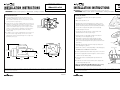
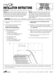
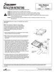
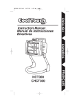
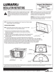
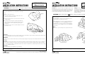
TM
TM
INSTALLATION INSTRUCTIONS
IMPORTANT: Read carefully before installing fixture. Retain for future reference.
VISION WALL
Sheet 4 of 4
12/29/03
IMI-498
WARNING: Make certain power is OFF before starting installation or attempting any maintenance.
Adjustment Of Light Throw
Your Vision Wall luminaire has an adjustable forward light
throw.
Adjustment
Screw
1. Obtain a 3/16" allen wrench.
INSTALLATION INSTRUCTIONS
IMPORTANT: Read carefully before installing fixture. Retain for future reference.
General: Upon receipt of fixture thoroughly inspect for any
freight damage, which should be brought to the attention of
the delivery carrier. Compare the catalog description listed
on the packing slip with the fixture label on the housing to
assure you have received the correct merchandise.
Your Vision Wall Luminaire has three different types of
mounting interface:
3. Turn the screw clockwise to pivot the reflector and throw
the light forward.
1. Standard Mount—mounts to any standard 4" J-box.
(Included with every fixture) (See Fig. 1).
Fig. 4
12/29/03
IMI-498
Safety: This fixture must be wired in accordance with
the national electrical code and applicable local codes
and ordinance. Proper grounding is required to insure
personal safety. Carefully observe grounding procedure
under installation section. All work should be done by a
qualified electrician.
WARNING: Make certain power is OFF before starting installation or attempting any maintenance.
2. Locate the stainless steel button head screw on the
outside of the fixture (See Fig. 4).
4. You may monitor the reflector rotation by viewing the
bottom edge of the reflector and the indicator located
inside the fixture. This is viewable through the glass
(See Fig. 5).
VISION WALL
Sheet 1 of 4
2. Embedded Mount—mounts to a plate embedded into
the wall (Optional Accessory VWM/EM) (See Fig. 2).
3. Thru Way Box—mounts to surface mounted casting,
allowing a conduit run (Optional Accessory VWM/TB)
(See Fig. 3).
5. Rotating the screw counter-clockwise brings the reflector
back down to zero.
Embedded Mount Kit
NOTE:
Please refer to your mounting kit for specific instructions.
Fig. 2
EMBEDDED MOUNT
VWM/EM
Thru Way Mounting
Degree Indicator
Fig. 5
CAUTION:
Prior to installing lamp in the fixture, verify that lamp source and wattage correspond with the fixture label. Lamp should
be screwed securely into the socket. Do not over tighten.
WARNING:
Recheck to be sure that the fixture has been wired properly. Improper wiring may result in ballast failure which voids all
warranties.
Cleaning
The reflector and door glass may be cleaned with any suitable non-abrasive glass cleaning solution, soap, or detergent
and rinse with clean water. The reflectors efficiency will be retained only if cleaned at regular intervals. Clean with mild
soap or detergent and water, or liquid wax emulsion. The refractor should also be cleaned along with the reflector, using
care not to chip glass surfaces.
Conduit run by others
4" J Box (By Others)
Standard Mount Kit
screws to J Box
Fig. 1
STANDARD MOUNT
Fig. 3
THRU-WAY BOX
VWM/TB
CAUTION:
Do not use abrasive, strong alkaline or acid cleaners.
These instructions do not claim to cover all details or variations in the equipment, procedure, or process described, nor to provide directions for meeting every possible
contingency during installation, operation or maintenance. When additional information is desired to satisfy a problem not covered sufficiently for user’s purpose, please
contact your nearest representative.
www.cooperlighting.com
Customer First Center 1121 Highway 74 South Peachtree City, GA 30269 770.486.4800 FAX 770.486.4801
AVU033142
AVU033142
TM
TM
VISION WALL
Sheet 2 of 4
INSTALLATION INSTRUCTIONS
12/29/03
IMI-498
IMPORTANT: Read carefully before installing fixture. Retain for future reference.
VISION WALL
Sheet 3 of 4
INSTALLATION INSTRUCTIONS
12/29/03
IMPORTANT: Read carefully before installing fixture. Retain for future reference.
WARNING: Make certain power is OFF before starting installation or attempting any maintenance.
IMI-498
WARNING: Make certain power is OFF before starting installation or attempting any maintenance.
Standard Mounting Kit
Installing the Fixture
1. The standard mounting kit may be mounted to any
standard, embedded, 4" junction box. It is not for use
with a surface mounted J-box. For orientation of fixture
to the junction box (See Fig. 1).
1. You may install the fixture with the light up or down,
as desired.*
2. Using the two (2) screws supplied with the junction box,
install the mounting plate as shown. The 5/16-18 studs
should be facing away from the wall and above the
center of the bracket (See Fig. 2). For rough or uneven
surfaces, sealant must be applied (by others) between
the rear mounting plate gasket and the mounting
surface (wall).
3. Visually inspect the mounting bracket to insure correct
placement and check for damaged gaskets (Refer to the
specific mounting instruction sheet used with your fixture.)
Reflector Latch
2. Make sure all power is off.
Apply Sealant
As Required.
See Note #2.
4. Loosen the four (4) 1/4-20 captive socket head cap
screws and open the door.
Fig. 2
Fig. 1
5. Locate two (2) reflector latches on either side of the
forward end of the reflector (See Fig. 1).
3. In addition to the screws supplied with the junction box,
the unit must be supported by 1/4" anchor screws
(supplied by others) installed through the four (4) holes
provided. (See Fig. 3).
6. Turn the latches to disengage and pivot the reflector
assembly out of the way (See Fig. 2).
7. Thread the incoming power leads through the large
center hole in the rear of the fixture while lining up the
bolts (or threaded studs) with the keyhole slots in the rear.
(See Fig. 3)
8. Carefully slide the fixture down the keyhole, taking care
not to damage the gaskets.
3 1/2"
(88.9mm)
9. Tighten the screws or nuts (Depending on mounting type).
DO NOT CAULK AROUND THE FIXTURE.
12 9/16”
(319.16mm)
Reflector
Door
Fig. 2
Thread Power Feed Lines
Thru Here
Mounting Studs
10. Have a qualified electrician make the power connections.
4 11/16"
(118.6mm)
11. Push the supply wires back through the center hole and
down in the rear fixture cavity.
6 5/16”
(161.2mm)
9 3/16”
(233.12mm)
12. Swing the reflector assembly back up and latch into
position.
Fig. 3
Fig. 1
13. Install the door and four (4) 1/4-20 screws. Tighten the
screws diagonally opposed.
* When used with Thru-Way Mounting Box Accessory
VWM/TB, unit can only be mounted downward.
These instructions do not claim to cover all details or variations in the equipment, procedure, or process described, nor to provide directions for meeting every possible
contingency during installation, operation or maintenance. When additional information is desired to satisfy a problem not covered sufficiently for user’s purpose, please
contact your nearest representative.
AVU033142
Fig. 3
These instructions do not claim to cover all details or variations in the equipment, procedure, or process described, nor to provide directions for meeting every possible
contingency during installation, operation or maintenance. When additional information is desired to satisfy a problem not covered sufficiently for user’s purpose, please
contact your nearest representative.
AVU033142