Transcript
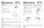
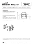
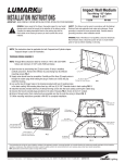
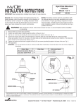
TM
INSTALLATION INSTRUCTIONS
VISION WALL
(VWS/VWM)
WIRE GUARD
2/17/04
IMI-508
IMPORTANT: Read carefully before installing fixture. Retain for future reference.
General: Upon receipt of fixture thoroughly inspect for any
freight damage, which should be brought to the attention of
the delivery carrier. Compare the catalog description listed
on the packing slip with the fixture label on the housing to
assure you have received the correct merchandise.
Safety: This fixture must be wired in accordance with
the national electrical code and applicable local codes
and ordinance. Proper grounding is required to insure
personal safety. Carefully observe grounding procedure
under installation section. All work should be done by a
qualified electrician.
WARNING: Make certain power is OFF before starting installation or attempting any maintenance.
1. Make certain all power is OFF before starting
installation.
4. THE DOOR SHOULD NOT BE REMOVED DURING
INSTALLATION.
2. Loosen and remove the existing component
(4) 1/4-20 socket head cap screws,
(4) teflon washers and (4) o-rings.
RETAIN FOR FUTURE REFERENCE.
5. Take all (4) 1/4 -20 socket head cap screws with washer, and
insert them into the wire guard then add the (4) molded
bushings to the opposite side of the 1/4-20 socket head cap
screws. (SEE FIG 1)
3. Assembly bag consist of the following:
a. Vision Wall Small (VWS)
(4) 1/4-20 lock nuts
(4) molded washer bushings
(4) 1/4-20 x 1.75” socket head cap screws
(4) 1/4-20 flat washer stainless steel.
6. Angle the door about 40º inward. Then, line up the wire guard
using the 1/4-20 screws and the 1/4-20 flat washer with the
holes in the door and pull the 1/4-20 screws through. Next,
take the 1/4-20 lock nuts and hand tighten to the door.
b. Vision Wall Medium (VWM)
(4) 1/4-20 lock nuts
(4) molded washer bushings
(4) 1/4-20 x 2" socket head cap screws
(4) 1/4-20 flat washer stainless steel
7. Close the door and tighten (4) 1/4-20 screws until the
door has been secured
8. To remove wire guard reverse steps starting with #7.
Fig. 1
These instructions do not claim to cover all details or variations in the equipment, procedure, or process described, nor to provide directions for meeting every possible
contingency during installation, operation or maintenance. When additional information is desired to satisfy a problem not covered sufficiently for user’s purpose, please
contact your nearest representative.
Customer First Center 1121 Highway 74 South Peachtree City, GA 30269 770.486.4800 FAX 770.486.4801
AVU040291