1
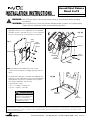
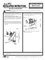
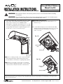
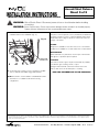
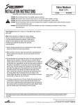
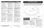
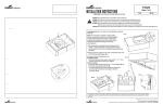
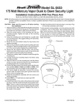
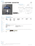
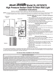
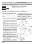
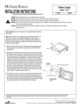
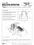
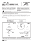
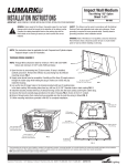
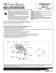
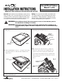
TM
Ascent/Strut Fixtures
Sheet 1 of 5
INSTALLATION INSTRUCTIONS
4/26/04
IMI-572
IMPORTANT: READ CAREFULLY BEFORE INSTALLING FIXTURE.
General: Upon receipt of fixture thoroughly inspect for any
freight damage, which should be brought to the attention of
the delivery carrier. Compare the catalog description listed
on the packing slip with the fixture label on the housing to
assure you have received the correct merchandise.
Safety: This fixture must be wired in accordance with
the national electrical code and applicable local codes
and ordinance. Proper grounding is required to insure
personal safety. Carefully observe grounding procedure.
All work should be done by an electrician.
WARNING: Risk of Electric Shock. Disconnect power at fuse or circuit breaker panel or
fuse box before installing or servicing.
WARNING: Risk of Personal Injury. Fixture may become damaged and/or unstable if not
installed properly. Tighten all fixture components to their recommended torque
values.
1. Open door by depressing LATCH BUTTONS into door and
lifting. (Fig. 1)
3. Disconnect PRIMARY QUICK-DISCONNECT by grabbing sides
and pulling away from fixture. (Fig. 3)
PRIMARY
QUICK
DISCONNECT
FUSES
STARTER
LATCH
BUTTONS
Fig. 1
2. Remove DOOR while it is at a 20° - 30° angle to the housing.
This will allow the door to slide over and forward from the
hinges. (Fig. 2)
Fig. 3
NOTE: Fusing and the cube starter are accessible from
the bottom, exposed side of the POWER TRAY. They
may be serviced without opening the POWER TRAY.
4. Hold POWER TRAY HANDLE and press POWER TRAY
LATCH away from the power tray. Hinge power tray up
and lift from fixture.
(Fig. 4)
Fig. 4
DOOR
POWER TRAY
HANDLE
POWER TRAY
LATCH
Fig. 2
These instructions do not claim to cover all details or variations in the equipment, procedure, or process described, nor to provide directions for meeting every possible
contingency during installation, operation or maintenance. When additional information is desired to satisfy a problem not covered sufficiently for user’s purpose, please
contact your nearest representative.
Customer First Center • 1121 Hwy 74 South • Peachtree City, GA 30269
IMI-572
AVU040062
TM
Ascent/Strut Fixtures
Sheet 2 of 5
INSTALLATION INSTRUCTIONS
4/26/04
IMI-572
IMPORTANT: READ CAREFULLY BEFORE INSTALLING FIXTURE.
WARNING: Risk of Electric Shock. Disconnect power at fuse or circuit breaker before installing
or servicing.
WARNING: Risk of Personal Injury. Fixture may become damaged and/or unstable if not installed properly.
Tighten all fixture components to their recommended torque values.
5. Using WALL PLATE as a template, drill (4) holes in wall. Install
appropriate wall anchors (not supplied) and secure GASKET
and WALL PLATE to wall with (4) 1/2-13 X 1-12 long BOLTS
and (4) Lockwashers (Fig. 5). Torque BOLTS to 450 in/lbs.
Fig. 6A
HOUSING
WALL
PLATE
Fig. 5
LOCK
WASHERS
GASKET
SPACER
BOLTS
HOLES
BOLTS
LOCK
WASHERS
WALL
BRACKET
FLAT
WASHERS
BOX
NOTE: The SPACER, WALL BRACKET and associated
components and hardware are shipped separately from the
fixture.
6. Assemble WALL BRACKET to SPACER and HOUSING with
(2) BOLTS, (2) FLAT WASHERS, and (2) LOCK WASHERS by
feeding BOLTS through holes in SPACER and into tapped
holes in WALL BRACKET. (Fig. 6A & 6B)
Torque BOLTS as follows:
• (2) 1/2 - 13 (AEM) = 450 in/lbs OR
• (2) 5/16 - 18 (AES) = 130 in/lbs
WARNING
Risk of Personal Injury
Fig. 6B
SUPPORT
BRACKET
Fixture may become damaged and/or
unstable if not installed properly
WALL
BRACKET
Tighten all fixture components to their
recommended torque values
These instructions do not claim to cover all details or variations in the equipment, procedure, or process described, nor to provide directions for meeting every possible
contingency during installation, operation or maintenance. When additional information is desired to satisfy a problem not covered sufficiently for user’s purpose, please
contact your nearest representative.
Customer First Center • 1121 Hwy 74 South • Peachtree City, GA 30269
IMI-572
AVU040062
TM
Ascent/Strut Fixtures
INSTALLATION INSTRUCTIONS
IMPORTANT: READ CAREFULLY BEFORE INSTALLING FIXTURE.
RETAIN FOR FUTURE REFERENCE.
Sheet 3 of 5
4/26/04
IMI-572
WARNING: Risk of Electric Shock. Disconnect power at fuse or circuit breaker before installing
or servicing.
7. Hook WALL BRACKET over WALL PLATE and place
SUPPORT BRACKET into SUPPORT HOLES in WALL PLATE
to support fixture as shown. (Fig. 7)
Make wire connections in WALL BRACKET.
Wire the fixture ground lead to the supply ground lead.
Wire the fixture voltage lead to the supply voltage lead.
Wire the fixture common lead to the supply common
lead.
8. Push SUPPORT BRACKET into WALL BRACKET and lower
fixture until WALL BRACKET fits over WALL PLATE. Tighten
1/4-20 SOCKET SCREW. (Fig. 8)
Fig. 8
NOTE: To wire to circuits not having a neutral lead (such
as 480V), connect the fixture voltage lead to one of the
supply leads and the fixture common lead to the other
supply lead.
WALL
BRACKET
Fig. 7
SOCKET
SCREW
NOTE: Ensure wires are not pinched while closing WALL
BRACKET to WALL PLATE.
WALL
BRACKET
WALL
PLATE
SUPPORT
BRACKET
SUPPORT
HOLES
These instructions do not claim to cover all details or variations in the equipment, procedure, or process described, nor to provide directions for meeting every possible
contingency during installation, operation or maintenance. When additional information is desired to satisfy a problem not covered sufficiently for user’s purpose, please
contact your nearest representative.
Customer First Center • 1121 Hwy 74 South • Peachtree City, GA 30269
IMI-572
AVU040062
TM
Ascent/Strut Fixtures
Sheet 4 of 5
INSTALLATION INSTRUCTIONS
4/26/04
IMI-572
IMPORTANT: READ CAREFULLY BEFORE INSTALLING FIXTURE.
WARNING: Risk of Electric Shock. Disconnect power at fuse or circuit breaker before installing
or servicing.
WARNING: Risk of Personal Injury. Fixture may become damaged and/or unstable if not installed properly.
Tighten all fixture components to their recommended torque values.
9. To reinstall POWER TRAY, hang POWER TRAY from POWER
TRAY HINGE, swing POWER TRAY up till POWER TRAY
LATCH snaps closed. Reconnect PRIMARY QUICK
DISCONNECT. Install lamp. Reinstall DOOR at 20°-30° angle
to housing, ensuring both hinges are engaged. Close DOOR,
ensuring DOOR LATCHES are completely engaged. (Listen
for both cams to “click” on each latch). (Fig. 9)
REFLECTOR Rotation/Removal:
10. Open DOOR by depressing LATCH BUTTONS into door.
(Reference Fig. 1)
11. To lower REFLECTOR, press the two REFLECTOR TABS
outward and swing the REFLECTOR down. (Fig. 11a & 11b).
The REFLECTOR may now be lifted off of its hinges for
rotation or removal.
Fig. 11a
Fig. 9
REFLECTOR
TABS
REFLECTOR
NOTE: Prior to installing the lamp, check to make sure lamp is of
proper type and wattage. Observe lamp manufacturer’s
recommendations and restrictions regarding lamp operation.
Fig. 11b
NOTE: Reflector are marked to insure reflector is installed in
proper orientation regarding “Street Side”. If other orientation
is desired, reflector may be rotated 90° in either direction.
REFLECTOR
TABS
REFLECTOR
These instructions do not claim to cover all details or variations in the equipment, procedure, or process described, nor to provide directions for meeting every possible
contingency during installation, operation or maintenance. When additional information is desired to satisfy a problem not covered sufficiently for user’s purpose, please
contact your nearest representative.
Customer First Center • 1121 Hwy 74 South • Peachtree City, GA 30269
IMI-572
AVU040062
TM
Ascent/Strut Fixtures
INSTALLATION INSTRUCTIONS
Sheet 5 of 5
4/26/04
IMI-572
IMPORTANT: READ CAREFULLY BEFORE INSTALLING FIXTURE.
WARNING: Risk of Electric Shock. Disconnect power at fuse or circuit breaker before installing
or servicing.
WARNING: Risk of Personal Injury. Fixture may become damaged and/or unstable if not installed properly.
Tighten all fixture components to their recommended torque values.
12. To remove the REFLECTOR, disconnect the REFLECTOR
CONNECTOR from the HOUSING. (Fig. 12)
Fig. 12
NEMA TWIST LOCK PHOTOCONTROL & RECEPTACLE:
The photocontrol receptacle is factory installed and ordered with
the fixture. The photocontrol is ordered separately and must be
field installed. The voltage of the photocontrol must match the
voltage of the fixture.
FUSING:
Single fuse is available for use with 120V, 277V or 347V fixture.
Double fuse is available for use with 208V, 240V or 480V fixtures.
MAINTENANCE:
When maintenance is performed, check torque on all fasteners
and tighten to specified torque if required.
REFLECTOR
CONNECTOR
13. To reinstall, reverse steps 12 and 11, listening for audible
clicks as REFLECTOR TABS engage REFLECTOR.
CLEANING:
The reflector and door glass may be cleaned with any suitable,
non-abrasive glass cleaning solution, soap or
detergent and rinsed with clean water. Please remove the
reflector and door from the fixture prior to cleaning.
KEEP THIS DOCUMENT FOR FUTURE REFERENCE
NOTE: This fixture is to be installed as a DOWNLIGHT ONLY.
This fixture is not suitable for UPLIGHT mounting
configurations.
These instructions do not claim to cover all details or variations in the equipment, procedure, or process described, nor to provide directions for meeting every possible
contingency during installation, operation or maintenance. When additional information is desired to satisfy a problem not covered sufficiently for user’s purpose, please
contact your nearest representative.
Customer First Center • 1121 Hwy 74 South • Peachtree City, GA 30269
IMI-572
AVU040062