1
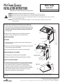
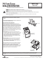
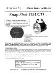
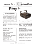
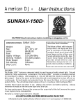
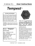
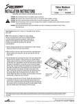
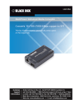
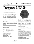
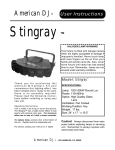
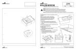
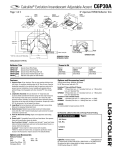
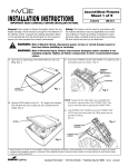
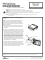
Talon Large
Sheet 1 of 3
INSTALLATION INSTRUCTIONS
11/29/07
IMPORTANT: READ CAREFULLY BEFORE INSTALLING FIXTURE.
IMI-682
WARNING: Risk of Fire/Electric Shock. If not qualified, consult an electrician.
WARNING: Risk of Electric Shock. Disconnect power at fuse or circuit breaker before installing or servicing.
WARNING: Risk of Burn. Disconnect power and allow fixture to cool before changing bulb or handling fixture.
WARNING: Risk of Personal Injury. Fixture may become damaged and/or unstable if not installed properly. Tighten all fixture components
to their recommended torque values.
WARNING: Risk of Fire/Electrical Shock. Upside down installation can result in overheating or accumulation of water in fixture.
Install right side up.
Tools Required Socket, 5/16" Socket, 3/4" Deep Well Socket, Electrical
wiring tools.
NOTE: These luminaires are designed for outdoor lighting services, and
should not be used in area of limited ventilation or in high ambient
temperature enclosures. Construction is suitable for down lighting only.
Best results will be obtained if installed and maintained according to the
following recommendations.
Latches
1. With the fixture on its back, open and remove door by pressing thumb
latches outward at the same time, open the door and lift it from the
hinges. FIG. 1
2. Run the two (2) threaded rods through the center of the semi-enclosed
hole details in the arm extrusion. To help orient the arm correctly with
the housing, please note that one end of the extruded arm has an angled
cut and the other has a perpendicular cut with two (2) drain notches
located on the bottom. If assembling to a round pole, use the round pole
adapter with the drain channels located at the extruded arm end with
the drain slots. Mate the angled side of the extruded arm to the housing
so that the bottom surface of the extrusion is parallel to the bottom of
the fixture, and the drain notches are facing down and located away
from the housing. FIG. 2 Slide the threaded rods into the interior of the
housing. Attach flat washer, lock washer, and nut into place in the order
shown in FIG. 2. Torque hex nuts to 450 lb/in.
3. If necessary, remove the cap on the pole. Position the housing and arm
to assemble it to the pole. Lower the nut plate into the interior of the
pole as shown. Slide the threaded rods through the pole and thread into
the nut plate until the rod protrudes though the nut plate slightly. Tighten
both nuts located inside of the housing to 30 lb/ft of torque.
FIG. 1
Nut Plate
Fits Inside
Of Pole
Round Pole Adapter (Optional)
Arm
FIG. 2
Mounting Rod (2)
Hardware: Washer,
Lock Washer, And
Hex Nut
These instructions do not claim to cover all details or variations in the equipment, procedure, or process described, nor to provide directions for meeting every possible contingency
during installation, operation or maintenance. When additional information is desired to satisfy a problem not covered sufficiently for user’s purpose, please contact your nearest
representative.
NOTE: Specifications and dimensions subject to change without notice.
Visit our web site at www.cooperlighting.com
Customer First Center 1121 Highway 74 South Peachtree City, GA 30269 770.486.4800 FAX 770.486.4801
ADH071365
Talon Large
Sheet 2 of 3
INSTALLATION INSTRUCTIONS
11/29/07
IMPORTANT: READ CAREFULLY BEFORE INSTALLING FIXTURE.
IMI-682
WARNING: Risk of Fire/Electric Shock. If not qualified, consult an electrician.
WARNING: Risk of Electric Shock. Disconnect power at fuse or circuit breaker before installing or servicing.
WARNING: Risk of Burn. Disconnect power and allow fixture to cool before changing bulb or handling fixture.
WARNING: Risk of Personal Injury. Fixture may become damaged and/or unstable if not installed properly. Tighten all fixture components
to their recommended torque values.
WARNING: Risk of Fire/Electrical Shock. Upside down installation can result in overheating or accumulation of water in fixture.
Install right side up.
4. With the pole and fixture(s) raised into position, place the power tray
onto the hinges of the housing electrical compartment and let it hang
free. Locate the power connector plug and rotate the power tray until the
connection can be made with the mating connector in the housing. Raise
the power tray until the two (2) thumbscrews engage and tighten until
fully snug. FIG. 3
FIG. 3
5. Replace door on the hinges at the rear of the housing, rotate into
position, and assure that both latches are fastened securely.
FIXTURE MAINTENANCE
Power Tray
RELAMPING
Thumbscrews (2)
1. Disengage both latches and open the door. Do not let the door swing
freely on the hinges.
FIG. 4
2. Replace the lamp with the appropriate type and wattage and reassemble
the refractor to the upper housing. FIG. 4
3. Close the door and assure that the latches are securely fastened.
NEMA PHOTOCONTROL REPLACEMENT
Latches
Lamp
1. The photocontrol is mounted on top the housing. FIG. 5
Removable Powertray
Lift And Hang On Hinges
2. Remove the photocontrol by twisting counterclockwise and replace.
Removable Door
Lift And Hang
Door On Hinges
PLUG-IN STARTER REPLACEMENT
1. This procedure applies to fixtures with a plug-in type starter. Disengage
both latches and open the door. Do not let the door swing freely on the
hinges. Loosen the power tray thumbscrews, unplug the power
connector as you lower the powertray, and continue lowering until the
powertray hangs free on the hinges. The starter is located in the position
shown. Remove and replace. Reverse the directions to secure the
powertray and the door after starter replacement.
NEMA Twistlock
Photocontrol
FIG. 5
These instructions do not claim to cover all details or variations in the equipment, procedure, or process described, nor to provide directions for meeting every possible contingency
during installation, operation or maintenance. When additional information is desired to satisfy a problem not covered sufficiently for user’s purpose, please contact your nearest
representative.
NOTE: Specifications and dimensions subject to change without notice.
Visit our web site at www.cooperlighting.com
Customer First Center 1121 Highway 74 South Peachtree City, GA 30269 770.486.4800 FAX 770.486.4801
ADH071365
Talon Large
Sheet 3 of 3
INSTALLATION INSTRUCTIONS
11/29/07
IMPORTANT: READ CAREFULLY BEFORE INSTALLING FIXTURE.
IMI-682
WARNING: Risk of Fire/Electric Shock. If not qualified, consult an electrician.
WARNING: Risk of Electric Shock. Disconnect power at fuse or circuit breaker before installing or servicing.
WARNING: Risk of Burn. Disconnect power and allow fixture to cool before changing bulb or handling fixture.
WARNING: Risk of Personal Injury. Fixture may become damaged and/or unstable if not installed properly. Tighten all fixture components
to their recommended torque values.
WARNING: Risk of Fire/Electrical Shock. Upside down installation can result in overheating or accumulation of water in fixture.
Install right side up.
2. Remove the plug-in starter from the receptacle and replace.
FIG. 6
3. Assure that the thumbscrews on the powertray and both latches
on the door are fastened securely.
OPTIC DISTRIBUTION AND ORIENTATION
The Talon Large fixture is offered with some optics that have
directional distributions. For aiming purposes, the Talon Large was
designed with the flexibility to allow each of its optics to be rotated
to any of four (4) positions, located at 90° increments. There are
two (2) mounting configurations that are used to mount all of the
Talon Large optics. The horizontally-lamped optics (as well as the
Type 4 vertical optic) use the horizontal optics adapter. All vertically
lamped optics use the vertical mount adapter.
1. Vertical Optics: Open the door and remove the lamp. Use a
screwdriver to slightly loosen (do not remove) the four (4) screws
as shown in FIG. 7. The optic has four (4) keyhole details that
allow it to release by turning the reflector clockwise a few
degrees allowing the optic to be removed. Reposition the optic
and tighten the screws securely.
2. Horizontal Optics: (this also covers the Type 4 vertical optic).
Open the door and remove the lamp. Use a screwdriver to
remove the four (4) screws as shown in FIG. 8. Reposition the
optic and reinsert the screws securely.
Plug-In Starter
FIG. 6
Thumbscrews
Remove Optic, Rotate
To Desired Position
And Fasten Into Place
FIG. 7
FIG. 8
These instructions do not claim to cover all details or variations in
the equipment, procedure, or process described, nor to provide
directions for meeting every possible contingency during
installation, operation or maintenance. When additional information
is desired to satisfy a problem not covered sufficiently for user's
purpose, please contact your nearest representative.
Remove Optic, Rotate
To Desired Position
And Fasten Into Place
These instructions do not claim to cover all details or variations in the equipment, procedure, or process described, nor to provide directions for meeting every possible contingency
during installation, operation or maintenance. When additional information is desired to satisfy a problem not covered sufficiently for user’s purpose, please contact your nearest
representative.
NOTE: Specifications and dimensions subject to change without notice.
Visit our web site at www.cooperlighting.com
Customer First Center 1121 Highway 74 South Peachtree City, GA 30269 770.486.4800 FAX 770.486.4801
ADH071365