1
Portable Chillers
VL Series, 0.25 to 1.5 ton models
Installation
Maintenance
Operation
Troubleshooting
Instant Access
Parts and Service
(800) 458-1960
(814) 437-6861
www.conairnet.com
The Conair Group, Inc.
One Conair Drive
Pittsburgh, PA 15202
Phone: (412) 312-6000
Fax: (412)-312-6227
UGH020/0301
Please record your
equipment’s model and
serial number(s) and
the date you received it
in the spaces provided.
It’s a good idea to record the model and serial number(s) of
your equipment and the date you received it in the User
Guide. Our service department uses this information, along
with the manual number, to provide help for the specific
equipment you installed.
Please keep this User Guide and all manuals, engineering
prints and parts lists together for documentation of your
equipment.
Date:
Manual Number:
UGH020/0301
Serial number(s):
Model number(s):
DISCLAIMER: The Conair Group, Inc., shall not be liable for errors
contained in this User Guide or for incidental, consequential damages in connection with the furnishing, performance or use of this
information. Conair makes no warranty of any kind with regard to
this information, including, but not limited to the implied warranties
of merchantability and fitness for a particular purpose.
Copyright 2001
THE CONAIR GROUP, INC.
All rights reserved
TABLE OF CONTENTS
1.0
GENERAL
1.1
Unit location
1.2
Efficiency
1.3
Safety
1.4
Clean air act
1.5
Miscellaneous
5
6
6
6
6
7
2.0
INSTALLATION
2.1
General
2.2
To and From process connections
2.3
Unit drain
2.4
Air-cooled condenser
2.5
Electrical connection
9
10
10
11
11
12
3.0
OPERATIONS SEQUENCE
3.1
General
3.2
Start up / operations procedure
3.3
Instrument operation
3.4
Shut down / disconnect sequence
13
14
14
15
18
4.0
TROUBLESHOOTING
4.1
Unit will not start
4.2
Pump will not start
4.3
Compressor will not start
4.4
Unit shuts down on high pressure switch
4.5
Unit shuts down on low pressure switch
19
20
20
20
20
20
5.0
MAINTENANCE
5.1
Warranty service procedure
5.2
Periodic preventative maintenance
5.3
Special maintenance
5.4
Pump repair
23
24
24
25
25
6.0
COMPONENTS
6.1
Water system
6.2
Refrigeration system
27
28
28
7.0
RELATED DRAWINGS
7.1
Electrical (typical)
7.2
Circuit schematic
29
30
31
8.0
APPENDIX
8.1
Specifications
8.2
Operations below 48°F
8.3
Water quality control
8.4
Inhibited propylene glycol
8.5
Chiller capacity and derate chart
8.6
Pressure - temperature chart for R-22
8.7
Engineering formulas
8.8
Spare parts list
33
34
35
37
37
39
40
41
42
UGH020/0301
VL Series Portable Chillers, 0.25 to 1.5 Tons
Page: 3
THIS PAGE INTENTIONALLY BLANK
Page: 4
VL Series Portable Chillers, 0.25 to 1.5 Tons
UGH020/0301
1.0
GENERAL
1.1
1.2
1.3
1.4
1.5
UGH020/0301
UNIT LOCATION
EFFICIENCY
SAFETY
CLEAN AIR ACT
MISCELLANEOUS
VL Series Portable Chillers, 0.25 to 1.5 Tons
Page: 5
1.1
1.2
UNIT LOCATION
A.
The unit is designed for indoor use only. For most efficient
operation, locate the chiller in a clean, dry and well ventilated
environment.
B.
The unit has an air-cooled refrigerant condenser. For air-cooled
condensers, a motor driven fan generates air flow through the
condenser to remove heat from the refrigerant system. The aircooled condenser on the unit will discharge a maximum of 15,000
BTUs per hour per ton of cooling.
C.
The unit must have a minimum entering air temperature of 60°F
and a maximum entering air temperature of 95°F for efficient
operation.
D.
The unit must have a minimum of two feet clearance at the air
intake and six feet at the exhaust air discharge.
E.
If the operator has any questions concerning the location and
operation of the unit, contact the Conair service department at
800-458-1960.
EFFICIENCY
A.
1.3
1.4
SAFETY
A.
It is important to become thoroughly familiar with this manual and
the operating characteristics of the unit.
B.
It is the owner’s responsibility to assure proper operator training,
installation, operation, and maintenance of the unit.
C.
Observe all warning and safety placards applied to the unit. Failure
to observe all warnings can result in serious injury or death to the
operator and sever mechanical damage to the unit.
CLEAN AIR ACT
A.
Page: 6
Long term efficiency of operation is largely determined by proper
maintenance of the mechanical parts of the unit and the water
quality. Conair recommends filtering where required to prevent
solids from plugging critical parts (pumps, heaters, seals for
example). Conair highly recommends the services of a competent
water treatment specialist be obtained and his recommendations
followed. Conair accepts no responsibility for inefficient operation,
or damage caused by foreign materials or failure to use adequate
water treatment.
The unit contains HCFC-22 (chlorodifloromethane). This is a class 2
substance.
VL Series Portable Chillers, 0.25 to 1.5 Tons
UGH020/0301
1.5
B.
Please be aware that effective July 1, 1992, it is unlawful for any
person in the course of maintaining, servicing, repairing, or
disposing of refrigeration equipment to knowingly vent or
otherwise dispose of any class 2 substance used as a refrigerant in
the manner which permits such substance to enter the
environment.
C.
De minimis releases associated with good faith attempts to
recapture, reclaim, or recycle such substance shall not be subject to
the prohibition set forth in the preceding paragraph.
MISCELLANEOUS
A.
The purpose of the unit is to circulate temperature stabilized fluid
through your process, resulting in process temperature control.
B.
The ability of the unit to maintain process temperature control is
significantly affected by the method of installation.
C.
If the operator has any questions concerning the location and
operation of the unit, please contact the Conair service at
800-458-1960 or 814-437-6861
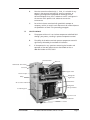
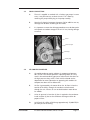
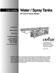
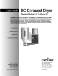
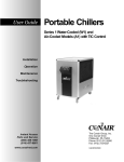
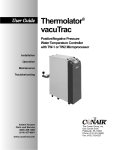
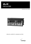
Electrical Panel
Reservoir
Illuminated ‘On’ Switch
Controller
Bypass Valve
Thermocouple
Refrigerant
Sight Glass
Pump
Filter-Drier
Air Cooled Condenser
Refrigerant
Safety Switches
Condensing Fan
Power Cord
Liquid Receiver
Caster
UGH020/0301
VL Series Portable Chillers, 0.25 to 1.5 Tons
Page: 7
THIS PAGE INTENTIONALLY BLANK
Page: 8
VL Series Portable Chillers, 0.25 to 1.5 Tons
UGH020/0301
2.0
INSTALLATION
2.1
2.2
2.3
2.4
2.5
UGH020/0301
GENERAL
TO AND FROM PROCESS CONNECTIONS
UNIT DRAIN
AIR COOLED CONDENSER
ELECTRICAL CONNECTION
VL Series Portable Chillers, 0.25 to 1.5 Tons
Page: 9
2.1
GENERAL
A.
All process piping materials (such as hose, rigid piping, valves or
filters) used in process water piping circuitry must be rated for
100°F minimum temperature and 100 PSI minimum pressure.
B.
All such materials must have the equivalent or larger diameter of
the particular process connection that length of process water
piping is connected to.
From process connection:
connect to “water out” on process manifold
To process connection:
connect to “water in” on process manifold
2.2
Page: 10
TO AND FROM PROCESS CONNECTIONS
A.
Connect the chiller’s “to process” connection to the “water in”
manifold on the mold or process.
B.
Connect the chiller’s “from process” connection the “water out”
manifold at the mold or process.
C.
Process water piping circuitry should be designed to avoid an
excessive use of elbows and/or lengths of pipe or hose. If hose is
the material of choice, avoid tight twists or curls and excessive
lengths.
D.
Valves and filters may be installed in the process water piping
circuitry to facilitate service and maintenance provided that such
devices maintain the full inside diameter of the process connection.
If installed, all such devices must be open and clean during unit
operation.
VL Series Portable Chillers, 0.25 to 1.5 Tons
UGH020/0301
2.3
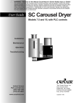
DRAIN CONNECTION:
A.
The unit is supplied as standard with a ProCon type pump. In some
cases, it may be necessary to drain the unit. This is done by
removing the pump volute plug in the pump assembly.
B.
Note that if chemical treatment of process fluid or additives are use,
drainage shall be done according to local codes.
C.
It is important to note that drainage procedures must be done prior
to shipment or outdoor storage or the unit. If not, freezing damage
can occur.
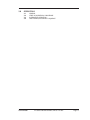
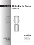
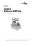
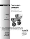
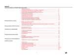
Motor
Thermocouple
Pump
Drain plug
2.4
UGH020/0301
AIR COOLED CONDENSER
A.
Air-cooled condenser require ambient air temperatures between
60°F and 95°F for efficient operation. Operating above 95°F may
result in elevated condensing pressures and eventual shut-down on
the high pressure safety switch. Check with the Conair service
department for more information on operating with ambient air
temperatures above 95°F or below 60°F.
B.
Air flow is generated by the motor driven fan. Air flow is from the
outside of the chiller, through the condenser and exhausted
through the unit. Exhaust air can not be ducted on motor driven
fan models.
C.
A free air space of at least four (4) feet is required at the condenser
intake and four (4) feet at the condenser discharge to allow for
proper air flow.
D.
At full load, this chiller will discharge approximately 15,000 BTU/hr
per hour per ton of cooling.
VL Series Portable Chillers, 0.25 to 1.5 Tons
Page: 11
2.5
ELECTRICAL CONNECTION
A.
C.
NEMA 1 MODELS
1.
Electrical power supply requirements for Nema 1 units
(figure 2.5A) are identified on the equipment data plate.
Verify that available voltage supply is the same as the unit’s
voltage requirements. WARNING: Do not connect the
unit to a voltage supply source not equal to the unit’s
voltage requirements as specified on the unit’s data
plate. Use of incorrect voltage will void the unit’s
warranty and cause a significant hazard that may result
in serious personal injury and unit damage.
2.
A factory supplied, four conductor cable is installed for
connection to a customer supplied fused power disconnect
device. The fused disconnect device shall be sized and
installed according to the unit’s power supply requirements
and local electrical codes.
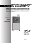
CONTROL CIRCUIT WIRING
1.
D.
The unit’s supplied control circuit is indicated in the
electrical diagrams. The control circuit is supplied by the
factory installed transformer.
GENERAL
1.
Make certain all ground connections to the unit are
properly affixed.
2.
Make certain power conductor, disconnect device, and
fusing are properly sized according to the unit’s power
supply requirements.
3.
Make certain all electrical connections are tightly affixed.
Any loose wiring connections must be tighten before
engaging the power supply.
4.
Make certain no moisture or standing water is present
inside the electrical cabinet.
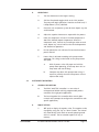
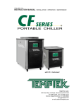
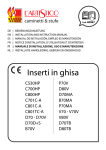
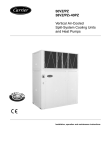
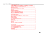
Microprocessor
controller
Page: 12
Transformer
Illuminated on/off
switch
VL Series Portable Chillers, 0.25 to 1.5 Tons
Motor starter
UGH020/0301
3.0
OPERATIONS
3.1
3.2
3.3
3.4
UGH020/0301
GENERAL
START UP/OPERATIONS PROCEDURE
INSTRUMENT OPERATION
SHUT DOWN/DISCONNECT SEQUENCE
VL Series Portable Chillers, 0.25 to 1.5 Tons
Page: 13
3.1
3.2
GENERAL
A.
Failure to follow the factory required operation procedures may
adversely affect the unit’s ability to control process temperature and
may create a hazardous operating condition which may result in
unit damage and serious operator injury or death.
B.
The Operations segment of this manual is outlined below:
Machine start-up/operations procedure - follow this
segment to start the unit after the initial installation or to
restart the unit after reinstallation to the same or different
process. This section includes information on system fill,
electric motor phasing (pump rotation) and process flow
adjustments.
3.3
Instrument - follow this segment to start up and operate
the instrument controller. This section includes information
on automatic and manual venting, setpoint selection and
adjustment, and feature explanations.
3.4
Shut down procedure - follow this segment to shut down
the unit. This segment includes information on system cool
down, shut down, electrical power supply precautions, and
disconnection from system.
START UP/OPERATIONS PROCEDURE
A.
Page: 14
3.2
SYSTEM FILL
1.
The unit has an internal reservoir which must be filled and
maintained for proper operation.
2.
Conair recommends the addition of 20% inhibited
propylene glycol to the process fluid. This should help
prevent the process fluid from freezing and internal
components from rusting. A biocide must be added to the
water to prevent organism growth in the chilled water
system. See water treatment section in section 8 of this
manual for more information.
3.
Remove the top panel
to access the reservoir.
Add fluid directly to the
reservoir tank. Please
note, when the pump is
first started, and after
the process lines are
filled and entrained air
is purged, additional
fluid may be required to
restore the reservoir to
the correct level.
Reservoir
VL Series Portable Chillers, 0.25 to 1.5 Tons
UGH020/0301
B.
3.3
OPERATIONS
1.
Turn the thermostat to the highest setting.
2.
Shift the illuminated toggle switch to the ‘ON’ position.
The pump will begin operations. Note the reservoir level, if
it drops below 3/4 full, add fluid.
3.
Check the unit and process system for leaks. Repair any that
are discovered.
4.
Adjust the setpoint thermostat as required for the process.
5.
Note, the compressor will start if the fluid temperature is
above the selected setpoint temperature. When the
compressor starts, listen for any knocking or other unusual
noise. Report any unusual noise to the Service department
and discontinue operations.
6.
Do not operate the unit without all sheet metal enclosure
panels secured.
7.
Process flow is adjusted according to the pump motor
amperage. This rating can be found on the pump motor
data plate.
With all process valves fully open and with the
pump motor operating, check amp draw with an
amp meter and note findings.
b.
Compare amp draw with pump motor rating. If
excessive, partially close the from process valve to
adjust motor amps.
INSTRUMENT OPERATION
A.
B.
GENERAL DESCRIPTION
A.
The EWPC 902/T/R/P controller is a new series of
microprocessor-based and fully programmable process
controllers for single point applications.
B.
The front keypad of this controller offers several alphanumeric menu prompts to configure the controller for each
specific application).
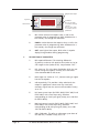
FRONT KEYPAD
1.
UGH020/0301
a.
SET: push to display the setpoint value. The setpoint can be
changed by using the “up” or “down” button. The control
will automatically switch back to normal operating mode
within 3 seconds. The last entered setpoint will stay in
memory.
VL Series Portable Chillers, 0.25 to 1.5 Tons
Page: 15
Output Status Light
Up Arrow
Down Arrow
UP
out
DOWN
SET
ewpc902t
C.
Page: 16
Set Button
Press for less than
3 seconds to change
setpoint.
Press for more than
4 seconds to access
parameters.
2.
UP: used to increase the setpoint value, as well as the
parameter when in programming. When held down for a
few seconds, the change rate accelerates.
3.
DOWN: used to decrease the setpoint value, as well as the
parameter when in programming. When held down for a
few seconds, the change rate accelerates.
4.
OUT: status light of the output, blinks when in setpoint
display/change mode or during programming.
DESCRIPTION OF PARAMETERS
1.
D1: setpoint differential. The switching differential
(hysteresis) can be set with positive value (make on rise) or
with negative value (make on fall). See parameter “HC1”.
2.
LS1: lower set. This is the lower limit below which the user
cannot change the setpoint; normally set at the lowest
value recommended for the sensor.
3
HS1: higher set. Similar to “LS1”, however setting an upper
limit for the setpoint.
4.
od: output delay. This provides a delay selection for the
outputs in applications where noise may cause brief
erroneous signals from the sensor to the controller. Factory
set at “0”.
5.
Lci: lower current input (for EWPC 902/R, EWPC 902/P and
EWPC 902/T with current input only). Read-out
corresponding to 4 mA input signal (factory set at 20 %R.H
for EWPC 902/R).
6.
Hci: high current input (for EWPC 902/R, EWPC 902/P and
EWPC 902/T with current input only). Read-out
corresponding to 20 mA input signal (factory set at 100
%R.H for EWPC 902/R).
7.
CAL: CALibration. This offers an adjustment up or down of
the read-out, if needed. Factory set at “0”.
VL Series Portable Chillers, 0.25 to 1.5 Tons
UGH020/0301
D.
UGH020/0301
8.
PSE: Probe SElection. Input type (for RTD or Thermocouples
only). RTD models: Ni = Ni100; Pt = Pt100. T/C models: FE
= TcJ; Cr = TcK; rh = TcS.
9.
HC1: Heating/Cooling. Relay switch function. H = heating
(humidification; reverse action); C = cooling
(dehumidification; direct action).
10.
rP1: relay Protection 1. Determines the status of the relay in
case of sensor defect. Factory set at “ro”. ro = relay open;
rc = relay closed.
11.
LF1: Led Function 1. Determines whether the status light in
ON or OFF in relation to output 1. di = direct = light ON
when output 1 is energized; in = reverse = light OFF when
output 1 is energized.
12.
dP: decimal Point. Choose whether the resolution is
required with or without decimal point. oF = without
decimal point; on = with decimal point.
13.
Notes: (a) the decimal point of models with current or
voltage input is shifted: the actual value of parameters “Lci”
and “Hci” must be multiplied by 10. (b) On all versions, if a
unit is changed from without decimal point to with decimal
point, all parameter values expressed in degrees will
automatically be divided by 10, including the setpoint! (c)
The decimal point selection is not available on models for
thermocouple input.
14.
hdd: half digit display. The right-most digit can be set to
read-out in 0 or 5 only, or in all 10 digits. hdd = n : e.g.
070, 071, 072 etc (if without decimal point) or 70.0, 70.1,
70.2 etc (if with decimal point.); hdd = y : e.g. 070, 075,
080, etc. (if without decimal point) or 70.0, 70.5, 80.0 etc,
(if with decimal point). Useful when measuring values
varying rapidly (e.g. %R.H.)
15.
tAb: tAble of parameters. This shows the configuration of
the parameters as set in the factory; can not be modified
(for factory identification and diagnostic purposes only).
PARAMETERS DEFAULTS
1.
Programming is easily accessed by holding the “SET”
button down for more than 4 seconds.
2.
The first parameter is displayed while the status light Led
“out” remains blinking during the programming period.
VL Series Portable Chillers, 0.25 to 1.5 Tons
Page: 17
DEFAULT SETTING - STANDARD MODLES
E.
3.4
DECRIPTION
RANGE
UNIT
d1
differential
min / max
C/ F
4
LS1
Lower Set
min / max
C/ F
40
HS1
Higher Set
min / max
C/ F
70
od
output delay
min / max
seconds
60
Lci
Low current input
min / max
various
0
Hci
High current input
min / max
various
0
CAL
CALibration
min / max
C/ F
0
PSE
Probe SElection
Ni / Pt / Fe / Cr / rh
/
Fe
HC1
Heating / Cooling
H/C
flag
C
rP1
relay Protection
ro / rc
flag
RO
LF1
Led Function
di / in
flag
OF
dp
decimal Point
on / oF
flag
N
hdd
half digit display
n/y
flag
tAb
tAble of parameter
/
flag
3.
Other parameters are accessed with the “UP” and “DOWN”
button. With the “SET” button, the actual setting of each
parameter is displayed. To change a parameter setting,
push the “SET” plus the “UP” (or “DOWN”).
4.
The system will automatically return to its normal operating
mode a few seconds after the programming procedure is
completed or interrupted.
ERROR ANNUNCIATION
1.
Any sensor input defect will be displayed as follows: “ - - - ”
in case of shorted sensor - “ EEE ”; in case of sensor break or
sensor absence. The “ EEE ” error message also appears in
the event of overrange of underrange of the system
temperature.
2.
It is recommended to double check the sensor wiring
before diagnosing a probe as defective.
SHUT DOWN/DISCONNECT SEQUENCE
A.
PRECAUTIONS/WARNINGS
1.
B.
The operator must precisely follow all shut down
procedures outlined in this manual. If the operator fails to
do so, an unsafe condition can develop resulting in damage
to the unit or injury and/or death to operating personnel.
UNIT SHUT DOWN (without system disconnect)
1.
Page: 18
FACTORY
PARAMETER
To shut down the unit: toggle ‘off’ the rocker switch and
disconnect the electrical supply.
VL Series Portable Chillers, 0.25 to 1.5 Tons
UGH020/0301
4.0
TROUBLESHOOTING
4.1
4.2
4.3
4.4
4.5
UGH020/0301
UNIT WILL NOT START
PUMP WILL NOT START
COMPRESSOR WILL NOT START
UNIT SHUTS DOWN ON HIGH PRESSURE SWITCH
UNITS SHUTS DOWN ON LOW PRESSURE SWITCH
VL Series Portable Chillers, 0.25 to 1.5 Tons
Page: 19
4.1
4.2
4.3
4.4
4.5
Page: 20
UNIT WILL NOT START
A.
Blow fuse at power supply - isolate open fuse and replace. Double
check fuse sizes against nameplate amperage.
B.
Low voltage - measure incoming voltage with meter, voltage must
be within 10% of nameplate voltage or warranty will be voided.
PUMP WILL NOT START
A.
Impeller bound or frozen shaft bearing in motor.
B.
Open motor winding.
C.
Internal overload tripped.
D.
Loose wire connection or defective start capacitor.
E.
On/off circuit breaker tripped.
COMPRESSOR WILL NOT START
A.
Safety switch open - unsafe condition exists (consult safety switch
section in this manual).
B.
Windings overheated - over temperature switch on compressor
tripped.
C.
Circuit breaker tripped - reset and check amperage. Verify voltage is
correct, check for loose wire connection at motor. Defective circuit
breaker.
D.
Bad or defective start capacitor.
UNIT SHUTS DOWN ON HIGH PRESSURE SWITCH
A.
Low air flow across condenser. Check for dirty condenser fins.
B.
Fan not operating. Check for loose fan blade or open/grounded
motor winding.
C.
High ambient air temperature (above 95°F).
D.
Insufficient clear space around unit.
UNIT SHUTS DOWN ON LOW PRESSURE SWITCH
A.
Attempting to operate below 40°F.
B.
Low refrigerant charge.
VL Series Portable Chillers, 0.25 to 1.5 Tons
UGH020/0301
UGH020/0301
C.
Restriction to refrigerant flow in refrigeration circuit.
D.
Poor heat transfer in evaporator tank because (1) percentage of
glycol to water is too high and (2) scaled tubes in evaporator tank
(chemically descale).
E.
Low flow through evaporator tank due to (1) process flow restricted
or (2) glycol foaming.
VL Series Portable Chillers, 0.25 to 1.5 Tons
Page: 21
THIS PAGE INTENTIONALLY BLANK
Page: 22
VL Series Portable Chillers, 0.25 to 1.5 Tons
UGH020/0301
5.0
MAINTENANCE
5.1
5.2
5.3
5.4
UGH020/0301
WARRANTY SERVICE PROCEDURE
PERIODIC PREVENTATIVE MAINTENANCE
SPECIAL MAINTENANCE
PUMP REPAIR
VL Series Portable Chillers, 0.25 to 1.5 Tons
Page: 23
5.1
5.2
WARRANTY SERVICE PROCEDURE
A.
In the event of a problem with a chiller that can not be resolved by
normal troubleshooting procedures, the customer is invited to
consult the Conair service department for assistance. The correct
model number and serial number of the chiller must be available.
The service department will attempt to isolate the problem and
advise repair procedures. Often times, with the customer’s input
and with the machine diagnostics, problems can be determined
with “over-the-phone” consultation.
B.
If the problem is beyond the scope of “over-the-phone”
consultation, and if the warranty status of the machine is valid,
Conair will contact the nearest authorized service contractor and
provide authorization to conduct an “on-site” inspection of the unit
in order to determine the course of repair. If the chiller is not
covered by the warranty, Conair will advise on the repair and
recommend available service contractors.
C.
Conair manufactures a complete line of heat transfer equipment. It
is of the utmost importance that Conair have the correct model
number and serial number of the machine in question. This will
allow Conair to obtain the correct manufacturing records which
will help the service department to properly troubleshoot the
problem and obtain the proper replacement parts when they are
required. This information is stamped on the metal data tag that is
attached to the machine.
D.
The Conair service department must be notified prior to any repair
or service of a warranty nature. Warranty claims will not be honored
without prior authorization.
PERIODIC PREVENTATIVE MAINTENANCE
Page: 24
A.
Lubricate all motors. Note that some motors are supplied with
sealed bearings.
B.
Tighten all wire terminals.
C.
Clean and check motor starter and contactor contacts.
D.
Check safety switch settings.
E.
Clean condenser fins of dust and dirt.
F.
Back flush evaporator.
G.
Check glycol/water solution ratio for operating temperature.
H.
Check system for leaks.
VL Series Portable Chillers, 0.25 to 1.5 Tons
UGH020/0301
5.3
I.
Refrigerant sight glass: check for bubbles when compressor is
operating at 100%. Check the moisture indicator for a color other
than green.
J.
Clean unit.
SPECIAL MAINTENANCE
A.
5.4
Any service of the refrigeration system must be accomplished by a
certified refrigeration technician.
1.
Vacuum check compressor.
2.
Addition of compressor oil.
3.
Addition of refrigerant.
4.
Repair of a refrigerant leak.
5.
Adjustment of super heat.
6.
Changing of filter-drier or drier core.
7.
Repair of a refrigeration solenoid.
8.
Valve plate replacement on compressor.
PUMP REPAIR
A.
The positive displacement pump in the unit is not field serviceable.
To arrange for repair contact:
PROCON PUMPS
910 RIDGELY ROAD
MURFEESBORO, TN 37310
615-890-5710
UGH020/0301
VL Series Portable Chillers, 0.25 to 1.5 Tons
Page: 25
THIS PAGE INTENTIONALLY BLANK
Page: 26
VL Series Portable Chillers, 0.25 to 1.5 Tons
UGH020/0301
6.0
COMPONENTS
6.1
6.2
UGH020/0301
WATER SYSTEM
REFRIGERATION SYSTEM
VL Series Portable Chillers, 0.25 to 1.5 Tons
Page: 27
6.1
WATER SYSTEM
A.
6.2
Page: 28
MOTOR/PUMP ASSEMBLY: the motor/pump assembly
circulates chilled fluid to the process loop. The pump assembly is
built of brass to maintain water quality.
REFRIGERATION SYSTEM
A.
COMPRESSOR: hermetic compressors take low pressure/low
temperature refrigerant gas and compress the gas into high
pressure/high temperature gas).
B.
AIR COOLED CONDENSER: the air cooled condenser removes
BTUs from the compressor refrigerant gas. The action causes the
gas to “condense” into a liquid state still under high pressure. Air
flow across the condenser is achieved via a motor driven fan.
C.
FILTER-DRIER: the filter-drier removes contaminants and
moisture from the liquid refrigerant.
D.
LIQUID RECEIVER: serves as a collection tank for high pressure
liquid refrigerant to ensure total charge at all times.
E.
REFRIGERANT SIGHT GLASS: the refrigerant sight glass
indicates refrigerant charge and moisture content. Refrigerant
charge is determined by a clear liquid flow. Bubbles indicate low
refrigerant. Moisture content is indicated by the color of the
element. Element color is normally green. If the color of the
element is chartreuse or yellow, the system has been
contaminated with moisture. In such case, the filter-drier must
be replaced. The replacement of the filter-drier must be
completed by a qualified refrigerant service technician.
F.
EXPANSION VALVE: the expansion valve throttles flow of
refrigerant liquid into the evaporator and creates a pressure drop
in the refrigerant system that allows the liquid refrigerant to “boil
off” inside the evaporator.
G.
EVAPORATOR: the evaporator is a tube in tube heat exchanger
where the refrigerant liquid is allowed to evaporate (boil off) to
absorb heat (BTU) from the process fluid. As the heat is
absorbed, the process fluid is chilled.
H.
HIGH/LOW PRESSURESTATS: the high/low pressurestats protect
the refrigeration system from unsafe operating levels. The high
pressure switch is factory set to open at 325 psi and protects
the refrigeration components and personnel from potential
damage of injury from excessive high pressure. The high pressure
safety must not be altered in the field for any reason. The low
pressure switch is factory set to open at 58 psi and to close at
63 psi. The low pressure switch protects the chillers from
possible damage due to low operating pressure. The low
pressure switch is field adjustable for setpoints below 48°F.
VL Series Portable Chillers, 0.25 to 1.5 Tons
UGH020/0301
7.0
RELATED DRAWINGS
7.1
7.2
UGH020/0301
ELECTRICAL DRAWING (TYPICAL)
CIRCUIT SCHEMATIC
VL Series Portable Chillers, 0.25 to 1.5 Tons
Page: 29
7.1
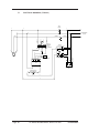
ELECTRICAL DRAWING (TYPICAL)
UNIT
ON/OFF
5
1
5
2
6
6
GREEN
BLU/YEL
BLU
7
5
6
230/1/60
PRIMARY
RELAY
24 VAC
SECONDARY
BLU
8
11
8
M1
GREEN
BLK/
BLK/YEL
BLK/RED
BLK/WHT
GREEN
POWER ENTRY
230/1/60
5
1
6
0
4
2
2
4
4
1
9
10
7
6
8
9
7
10
8
9
TYPE "J"
THERMOCOUPLE
3
11
11
5
Page: 30
3
DUAL HIGH-LOW
PRESSURESTAT
4
10
ELIWELL
902T
1
3
C
5
13
GREEN
2
PUMP
R
CONDENSING
UNIT
13
11
5
11
5
VL Series Portable Chillers, 0.25 to 1.5 Tons
UGH020/0301
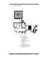
7.2
CIRCUIT SCHEMATIC
2
11
10
12
1
3
7
4
5
ITEM
1
2
3
4
5
6
7
8
9
10
11
12
UGH020/0301
6
9
8
DESCRIPTION
Compressor
Air cooled condenser
Liquid receiver
Filter-drier
Refrigerant sight glass
Expansion valve
Evaporator
Pump
To process connection
From process connection
Reservoir tank
Refrigerant safety switch
VL Series Portable Chillers, 0.25 to 1.5 Tons
Page: 31
THIS PAGE INTENTIONALLY BLANK
Page: 32
VL Series Portable Chillers, 0.25 to 1.5 Tons
UGH020/0301
8.0
APPENDIX
8.1
8.2
8.3
8.4
8.5
8.6
8.7
8.8
UGH020/0301
SPECIFICATIONS
OPERATION BELOW 45°F
WATER QUALITY CONTROL
INHIBITED PROPYLENE GLYCOL
CHILLER CAPACITY AND DERATE CHART
PRESSURE - TEMPERATURE CHART FOR R-22 REFRIGERANT
ENGINEERING FORMULAS
SPARE PARTS LIST
VL Series Portable Chillers, 0.25 to 1.5 Tons
Page: 33
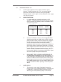
8.1
SPECIFICATIONS
VL Air-cooled Portable Chillers: 0.25 to 1.5 tons
MODEL
VLA-.25
Performance characteristics
Capacity* tons
0.25
Compressor Hp {kW}✝
0.25 {0.19}
Pump Hp {kW}
0.25 {0.19}
Chilled water flow‡ gpm {lpm}
0.6 {2.3}
Chilled water pressure‡ psi {bar} 60 {4.1}
Reservoir capacity gal {liters}
4 {15}
Dimensions in {mm}
Height
33 {838}
Width
18 {457}
Depth
24 {610}
Pipe size NPT in.
Process (to and from)
0.5
Condenser
—
Weight lb {kg}
Shipping§
150 {68}
Voltages full load amps**
115V/1 phase/60Hz
11
220V/1 phase/60Hz
—
Refrigerant
VLA-.33
VLA-.5
VLA-.75
VLA-1
VLA-1.5
0.32
0.33 {0.25}
0.25 {0.19}
0.8 {3.0}
60 {4.1}
4 {15}
0.41
0.5 {0.37}
0.25 {0.19}
0.9 {3.4}
60 {4.1}
4 {15}
0.70
0.75 {0.56}
0.25 {0.19}
1.7 {6.4}
60 {4.1}
4 {15}
0.98
1 {0.75}
0.5 {0.37}
2.4 {9.1}
60 {4.1}
4 {15}
1.35
1.5 {1.1}
0.5 {0.37}
3.6 {13.6}
60 {4.1}
4 {15}
33 {838}
18 {457}
24 {610}
33 {838}
18 {457}
24 {610}
33 {838}
18 {457}
24 {610}
33 {838}
18 {457}
24 {610}
37 {940}
19 {483}
25 {635}
0.5
—
0.5
—
0.5
—
0.5
—
0.75
—
150 {68}
170 {77}
205 {93}
210 {95}
220 {100}
12
—
14
8
HCFC-22
22
11
24
12
—
15
SPECIFICATION NOTES
* Ton capacity at 12,000 BTU/ton @ 50°F leaving water temperature @ 115°F condensing temperature. Capacities
may be ± 5% as reserved by the compressor manufacturer. Capacity multipliers are: 50°F - 1.00; 40°F - 0.80;
30°F - 0.60; 20°F - 0.40.
✝ Hermetic reciprocating compressor.
‡ Consult pump curve for exact characteristics relating to pump performances.
§ Unit weight crated for shipment
** No allowance for inrush. Service disconnect by owner. Full load amps must be used to size disconnects and
supply conductors. Consult factory for 50hz operation.
Specifications can change at any time. Contact your Conair representative for the most current information.
Page: 34
VL Series Portable Chillers, 0.25 to 1.5 Tons
UGH020/0301
8.2
OPERATION BELOW 48°F
A.
A chiller typically operates with a setpoint of 50°F or higher.
However, if setpoints between 20° - 48°F are required, special
precautions must be taken to prevent freezing and possible
damage. Attention must be given to freeze protection, water supply
and safety adjustments.
B.
FREEZE PROTECTION
1.
It is understood that untreated water freezes at 32°F.
Therefore, an inhibited propylene glycol and water solution
must be used in lieu of ordinary water. Prescribed amounts
are listed in figure 8.2A.
OPERATING
ANTI-FREEZE MIXTURE
TEMPERATURE
GLYCOL
WATER
40°F
25°F
30°F
20%
25%
30%
80%
75%
70%
Figure 8.2A
C.
2.
On initial installation of the unit, the water/glycol solution
should be premixed, then added to the reservoir. After the
pump has been started, water lines filled and air purged, it
may be necessary to add more water/glycol solution to
maintain the recommended reservoir level. Note: a
hygrometer should be used on a regular basis to determine
the mixture strength according to freeze point. The freeze
point temperature should be 25° below the lowest required
setpoint. Water will evaporate from the mixture, and if you
continue to add a premixed solution eventually you will
have too much glycol. It is necessary to add water or glycol
to maintain proper freeze point temperature.
3.
PLEASE NOTE THAT A CHILLER IS NOT DESIGNED TO
ACCOMMODATE AUTOMOTIVE TYPE ANTI-FREEZE. This
is due to the fact that automotive type anti-freeze contains
silicates that adhere to heat transfer surfaces of the system
preventing maximum heat transfer. Also, improper portions
of inhibited propylene glycol to water inhibits effective heat
transfer. Consult the chiller’s operating manual for specific
details.
WATER SUPPLY
1.
UGH020/0301
The automatic water supply (if equipped) restores the
reservoir water level as needed. However, if untreated water
is added to an water/glycol solution, dilution will occur
decreasing the freeze protecting ability of the solution.
VL Series Portable Chillers, 0.25 to 1.5 Tons
Page: 35
Therefore, the water supply source must be disconnected
and the connection capped. The operator must monitor the
water/glycol level and manually make-up to maintain
proper reservoir level.
D.
SAFETY ADJUSTMENTS
1.
To ensure safe and efficient operations at lower setpoints,
adjustments of the freezestat and low pressurestat factory
settings are required. Figure 8.2B lists the appropriate
settings.
Figure 8.2B
E.
2.
The freezestat serves as the mainline defense
against freezing in that it shuts down the chiller if the
coolant temperature ever decreases to its setting. For
mechanical freezestats, adjustments are made by removing
the cover and rotating the selector dial with a screwdriver.
Electronic freezestats are adjusted through the setup
parameters via the instrument control panel.
3.
The low pressurestat serves to protect the compressor from
unsafe suction pressures. Suction pressures decrease with
lower operating setpoints. To prevent short cycling of the
compressor, the low pressurestat must be adjusted to
accommodate the lower setpoint. Adjustments to the low
pressurestat are made by rotating the adjusting screws on
top of the control and observing the movement of the
pointers in the control window until the prescribed setting
is determined.
PRECAUTIONS
1.
Page: 36
At any setpoint, the possibility of freezing exists and it is the
operator’s responsibility to take necessary action to prevent
freezing at all times.
VL Series Portable Chillers, 0.25 to 1.5 Tons
UGH020/0301
8.3
8.4
WATER QUALITY CONTROL
A.
Lack of, as well as, improper water treatment can damage the
chilling unit. The services of a competent water treatment specialist
should be obtained and their recommendations followed. It is the
equipment owner’s responsibility to prevent damage from foreign
material or inadequate water treatment.
B.
The two main things to consider for water treatment in chillers are
corrosion and organism growth. Proper chemical treatment can
control PH levels and algae growth. An alternative to chemical
treatment is the addition of 20% inhibited propylene glycol to the
water. This will help prevent organism growth and coat the heat
transfer surfaces with corrosion inhibitor.
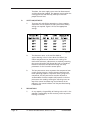
INHIBITED PROPYLENE GLYCOL
A.
B.
The use of a water-glycol
mixture is needed when
the operator desires a
process temperature
below 48°F. Freeze
protection is required so
ice crystals do not form
and cause severe damage
to both the water and
refrigeration system.
CHOOSING THE PROPER
GLYCOL:
FREEZING POINTS FOR
WATER/PROPYLENE GLYCOL SOLUTIONS
PERCENTAGE OF
GLYCOL* WATER
0
10
20
30
40
50
60
FREEZE POINT
˚F ˚C
100
90
80
70
60
50
40
32
25
10
0
-10
-30
-60
0
-3.9
-12.2
-17.8
-23.3
-34.4
-51.4
*PROPLYLENE GLYCOL
NOTE: GLYCOL FREEZE POINT MUST BE 25˚F BELOW
LOWEST SETPOINT
1.
For getting the most efficiency from your system, a
propylene glycol such as “DowFrost” is a must. DowFrost
contains special corrosion inhibitors for low system
maintenance and better transfer capabilities than normal
glycols. It also has a much longer fluid life up, to 20 years
in some cases.
2.
SOURCES OF INHIBITED PROPYLENE GLYCOLS: for a
complete literature package, material, safety data sheets
and purchasing information, contact the following:
DOW CHEMICAL 1-800-447-4369
(Canada 1-800-363-6250)
Dowfrost inhibited propylene glycol
MONSANTO CHEMICAL 1-800-459-2665
Monsanto FS inhibited propylene glycol
UGH020/0301
VL Series Portable Chillers, 0.25 to 1.5 Tons
Page: 37
C.
USE OF PLAIN GLYCOL:
1.
D.
AUTOMOTIVE BASED ANTIFREEZE:
1.
E.
Even through they do lower the freeze point, plain glycols
are even more corrosive than water. The corrosion rate of
plain ethylene glycol on iron, for example, is more than 2.5
times faster than plain water. On steel, it is 4.5 times faster.
SHOULD NEVER BE USED! Automotive antifreeze contains
silicate based inhibitors, which are compatible with
automotive components. In an industrial application, the
silicates will leach out and form a gel-like substance on the
heat transfer surfaces and reduce cooling efficiency of the
system. These silicates have shown to significantly reduce
the lifetime of pump seals.
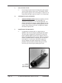
MAINTENANCE RESPONSIBILITY:
1.
A hygrometer should be used on a regular basis to
determine the mixture strength according to freeze point.
The freeze point temperature should be 25°F below the
lowest required setpoint (see charts on page 35 and 37).
Water will evaporate from the mixture, and if you continue
to add a premixed solution, eventually you will have too
much glycol. It is necessary to add water or glycol to
maintain proper freeze point temperature. The device
pictured is by far the most accurate and easy to use for
maintaining and checking for proper glycol levels.
Contact:
Misco Products:
1-800-358-1100
Model #7084VP
Page: 38
VL Series Portable Chillers, 0.25 to 1.5 Tons
UGH020/0301
8.5
CHILLER CAPACITY AND DERATE CHART
Standard chiller rating is at 50°F. For all other temperature settings,
output tonnage is altered as follows:
OUTPUT FULL
TEMPERATURE AVAILABLE %
°F CAPACITY
60
105%
50
100%
45
90%
40
80%
35
70%
30
60%
25
50%
20
40%
15
30%
*
10
22%
*
5
15%
*
0
9%
*
-5
5%
*
NOTES:
If operation of the chiller at less than 48°F is
required, an inhibited propylene glycol
solution is required.
Consult factory for chiller operation below
20°F.
Ambient conditions affect air cooled chiller
operation and capacity. Standard rating is at
95°F entering air temperature. For ambient
air conditions greater than 95°F, chiller
derating will occur. For ambient temperatures
of 95-105°F, select the next larger capacity
chiller. For ambient temperatures over 105°F,
consult factory.
* These ranges require special options.
UGH020/0301
VL Series Portable Chillers, 0.25 to 1.5 Tons
Page: 39
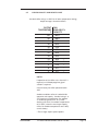
8.6
PRESSURE-TEMPERATURE CHART FOR R-22 REFRIGERANT
SATURATED TEMPERATURE
FREON PRESSURE
40°F
68
45°F
76
50°F
84
55°F
93
60°F
100
65°F
112
70°F
122
75°F
132
80°F
144
85°F
156
90°F
168
95°F
182
100°F
196
THESE PRESSURE/TEMPERATURE RELATIONSHIPS ARE IN AN
AT-REST, SATURATED CONDITION. FOR EXAMPLE, IF THE UNIT HAS BEEN IN A WAREHOUSE AT 40° AND IS
BROUGHT INTO A ROOM WHERE IT IS 80°, IT MAY TAKE A COUPLE OF HOURS FOR THE UNIT TO WARM UP AND
THE PRESSURE TO RISE TO THE SURROUNDING AMBIENT CONDITIONS.
Page: 40
VL Series Portable Chillers, 0.25 to 1.5 Tons
UGH020/0301
8.7
UGH020/0301
USEFUL ENGINEERING FORMULAS
VL Series Portable Chillers, 0.25 to 1.5 Tons
Page: 41
8.8
PARTS LIST
PART
800000
810000
895010
1527475
2169475
2971475
4345900
4714350
6206498
6214050
6648300
7550000
7591075
7732200
8213775
8828995
DESCRIPTION
Caster - 3” swivel
Caster - 3” rigid
Coil - Chas 3100
Condensing unit #F3AHA101CFV-201 203-1-60 R-22
Filter drier - C-0525
Expansion valve - #EVGE-1-CP100
CONTROLLER - #EWPC 902T Type J
Pump motor - 1/2 HP 1725 RPM 230-1-60 #3K090
Thermocouple - Type J ungrounded #SP-498J A4 B48
Procon pump - #CB2507XH AMP #1113
Relay - #GL7-2A-TUBJ-CB 230 volt
Pressure switch - P70MA-1
Rocker switch - #2600A21E
Reservoir tank - #06299
Transformer - #44F3095
Bypass valve - #5300A 1/2”
Note: this is a typical parts list. Please obtain exact model # and serial # before contacting
our parts department to assure an exact replacement part.
Page: 42
VL Series Portable Chillers, 0.25 to 1.5 Tons
UGH020/0301
Conair has made the largest investment in customer support in
the plastics industry. Our service experts are available to help
with any problem you might have installing and operating
your equipment. Your Conair sales representative also can help
analyze the nature of your problem, assuring that it did not
result from misapplication or improper use.
WE’RE HERE
TO HELP
To contact Customer Service personnel, call:
HOW TO CONTACT
CUSTOMER
SERVICE
From outside the United States, call: 814-437-6861
You can commission Conair service personnel to provide onsite service by contacting the Customer Service Department.
Standard rates include an on-site hourly rate, with a one-day
minimum plus expenses.
If you do have a problem, please complete the
following checklist before calling Conair:
❒ Make sure you have all model, serial and parts list
numbers for your particular equipment. Service
personnel will need this information to assist you.
BEFORE YOU
CALL ...
❒ Make sure power is supplied to the equipment.
❒ Make sure that all connectors and wires within
and between control systems and related
components have been installed correctly.
❒ Check the troubleshooting guide of this manual
for a solution.
❒ Thoroughly examine the instruction manual(s)
for associated equipment, especially controls.
Each manual may have its own troubleshooting
guide to help you.
❒ Check that the equipment has been operated as
described in this manual.
Additional manuals and
prints for your Conair
equipment may be
ordered through the
Customer Service or
Parts Departments for a
nominal fee.
❒ Check accompanying schematic drawings for
information on special considerations.
IMS0002/0296
SERVICE INFORMATION
APPENDIX A-1
EQUIPMENT
GUARANTEE
Conair guarantees the machinery and equipment on this order,
for a period as defined in the quotation from date of shipment,
against defects in material and workmanship under the normal
use and service for which it was recommended (except for
parts that are typically replaced after normal usage, such as
filters, liner plates, etc.). Conair’s guarantee is limited to
replacing, at our option, the part or parts determined by us to
be defective after examination. The customer assumes the cost
of transportation of the part or parts to and from the factory.
PERFORMANCE
WARRANTY
Conair warrants that this equipment will perform at or above
the ratings stated in specific quotations covering the equipment or as detailed in engineering specifications, provided the
equipment is applied, installed, operated and maintained in the
recommended manner as outlined in our quotation or specifications.
Should performance not meet warranted levels, Conair at its
discretion will exercise one of the following options:
● Inspect the equipment and perform alterations or adjustments to satisfy performance claims. (Charges for such
inspections and corrections will be waived unless failure
to meet warranty is due to misapplication, improper
installation, poor maintenance practices or improper operation.)
● Replace the original equipment with other Conair equipment that will meet original performance claims at no
extra cost to the customer.
● Refund the invoiced cost to the customer. Credit is subject to prior notice by the customer at which time a
Return Goods Authorization Number (RGA) will be
issued by Conair’s Service Department. Returned equipment must be well crated and in proper operating condition, including all parts. Returns must be prepaid.
Purchaser must notify Conair in writing of any claim and provide a customer receipt and other evidence that a claim is
being made.
WARRANTY
LIMITATIONS
APPENDIX A-2
Except for the Equipment Guarantee and Performance
Warranty stated above, Conair disclaims all other warranties
with respect to the equipment, express or implied, arising
by operation of law, course of dealing, usage of trade or otherwise, including but not limited to the implied warranties of
merchantability and fitness for a particular purpose.
WARRANTY INFORMATION
IMS0003/0796