1
CVG-606xl
6x6 Video/Audio Matrix Switcher
CVG-808xl
8x8 Video/Audio Matrix Switcher
USER MANUAL
CONTENTS
1
INTRODUCTION
3
1.1
A Word on Video/Audio Switchers
3
1.2
Factors Affecting Quality of Results
3
2
SPECIFICATIONS
4
3
HOW DO I GET STARTED?
4
4
UNPACKING AND CONTENTS
5
4.1
5
Optional Accessories
5
GETTING TO KNOW YOUR MATRIX SWITCHER
5
5.1
Your CVG-606xl Matrix Switcher
5
5.2
Features of the CVG-606xl Matrix Switcher
5
6
INSTALLATION
8
Rack Mounting
8
6.1
7
CONNECTING TO VIDEO DEVICES
8
8
CONNECTING TO AUDIO DEVICES
8
9
USING THE MACHINES
8
9.1
Powering on the Machine
8
9.2
Using the Front Panel Controls
8
Selecting an Output
9.2.2 Selecting an Input
9.2.3 Connecting a Video/Audio Input/Output
9.2.4 Disconnecting a Video/Audio Input
9.2.5 Connecting a Video/Audio Input to All Outputs
9.2.6 Selecting Video/Audio Control (Breakaway)
9.2.7 Using the Audio Follow Video Mode
9.2.8 Storing a Configuration
9.2.9 Recalling a Configuration
9.2.10
Deleting a Setup
9.2.11
Using the Take Function
9.2.12
Resetting the Machine
8
9
9
9
9
9
9
9
9
9
9
9
9.2.1
9.3
Using the Back Panel Controls
9.3.1
9.3.2
Selecting the Sync Source
Setting the Configuration Switches
10
10
9
9.4
RS-232 and RS-485 Operation
10
10 TYPICAL APPLICATIONS
12
10.1
Basic Video-Audio Setup
12
10.2
Component Switching using Multiple Matrix Switchers
12
10.2.1
10.2.2
RGB/YUV Switching with RS-232 (e.g. PC Control)
RGB/YUV Switching with RS-485 Control (or no External Control)
11 TAKING CARE OF YOUR MATRIX SWITCHER
1
13
13
13
12 TROUBLESHOOTING
14
12.1
Power and Indicators
14
12.2
Video Signal
14
12.3
Audio Signal
15
12.4
Control
15
12.5
Switching Malfunctions
16
13 COMMUNICATION PROTOCOL
16
FIGURES
FIGURE 1: CVG-606XL FRONT/REAR PANEL FEATURES
FIGURE 2: DIP SWITCHES GENERAL VIEW
FIGURE 3: RS-232 CONTROL CONNECTOR WIRING
FIGURE 4: RS-232 AND RS-485 OPERATION
FIGURE 5: TERMINATING THE LINE
FIGURE 6: BASIC VIDEO-AUDIO SETUP
6
10
11
11
11
12
TABLES
TABLE 1: CVG-606XL FRONT PANEL FEATURES
TABLE 2: CVG-606XL REAR PANEL FEATURES
6
7
2
1
INTRODUCTION
Congratulations on purchasing your Matrix Switcher. This user manual describes the following products:
CVG-606xl
CVG-808xl
1.1
A Word on Video/Audio Switchers
A video/audio switcher usually switches between several sources (inputs) and one or more acceptors (outputs).
A switcher that allows several inputs to be connected to several outputs simultaneously is called a Matrix
Switcher. Switchers may be of the electronic or mechanical type. Most matrices are of the active electronic type,
with many crosspoints. Vertical Interval Switching, frequently used in video, ensures that the transition from
one video source to another (such as switching between two genlocked cameras) is smooth and without
interference. The switching and changeover is done during the blanked vertical interval period, when the
transition is hidden from the eyes. Vertical Interval Switching is needed when recording or transmitting a video
program involving several video sources, as in live broadcast, to ensure clean, undisturbed picture transitions.
The switched sources should be genlocked. Matrices and switchers may sometimes be RS-232 or RS-485/422
controlled. Each of these options is a way of remotely controlling a video/audio device (switcher etc.) using a
PC with a serial port, or another device that uses a similar communication protocol. The simplest connection
between the RS-232 controller and the controlled device uses two wires (TRANSMIT, RECEIVE) and a
common ground wire. Finally, the wide video bandwidth permits the Matrix Switchers to be used in the most
demanding applications.
1.2
Factors Affecting Quality of Results
There are many factors affecting the quality of results when signals are transmitted from a source to an acceptor:
Connection cables - Low quality cables are susceptible to interference, they degrade signal quality due
to poor matching and cause elevated noise levels. They should therefore be of the best quality.
Sockets and connectors of the sources and acceptors - So often ignored, they should be of highest
quality, since "Zero Ohm" connection resistance is the target. Sockets and connectors also must match
the required impedance (75ohm in video). Cheap, low quality connectors tend to rust, thus causing
breaks in the signal path.
Amplifying circuitry - Must have quality performance when the desired end result is high linearity, low
distortion and low noise operation.
Distance between sources and acceptors - Plays a major role in the final result. For long distances
(over 15 meters) between sources and acceptors, special measures should be taken in order to avoid cable
losses. These include using higher quality cables or adding line amplifiers.
Interference from neighboring electrical appliances - These can have an adverse effect on signal
quality. Balanced audio lines are less prone to interference, but unbalanced audio should be installed far
from any mains power cables, electric motors, transmitters, etc. even when the cables are shielded.
3
2
SPECIFICATIONS
CVG-606XL
CVG-808XL
Configuration 6x6
6 composite video,
Input Type
1 sync/video genlock with
sync select switch,
6 stereo audio
Video: BNC connectors
Input
Audio: RCA connectors
Connections
Composite video:
Input Level
1Vpp/75ohm,
Sync/video genlock:
1Vpp/75ohm
Audio: +4dBm/62kohm
Output Type 6 composite video
6 audio stereo
Video: BNC connectors,
Output
Audio: RCA connectors
Connector
Output Level Composite video:
1Vpp/75ohm
Audio: +4dBm/50ohm
(27Vpp max.)
74dB
Video S/N
Ratio
88dB unweighted, (1Vpp)
Audio S/N
Ratio
Exceeding 200MHz
Video
Bandwidth
Exceeding 100kHz
Audio
Bandwidth
0.05%
Differential
Gain
0.03Deg.
Differential
Phase
<0.05%
K-Factor
Non Linearity <0.1%
<-50dB @ 5MHz
Video
Crosstalk
0.016% (1V, 1KHz)
THD
2nd Harmonic 0.004%
Switch System Vertical interval
Control Type Manual, RS-232 or
RS-485
11VA
Power
Consumption
3.4 kg (7.5lbs.) Approx.
Weight
19" x 7" x 2U
Dimensions
(H x W x D)
Power Source 230VAC, 50/60 Hz,
(115VAC, U.S.A.)
3
8x8
8 composite video,
1 sync/video genlock with
sync select switch,
8 stereo audio
Video: BNC connectors
Audio: RCA connectors
Composite video:
1Vpp/75ohm,
Sync/video genlock:
1Vpp/75ohm
Audio: +4dBm/33kohm
8 composite video
8 audio stereo
Video: BNC connectors,
Audio: RCA connectors
Composite video:
1Vpp/75ohm
Audio: +4dBm/50ohm
(24Vpp max.)
74dB
88dB unweighted, (1Vpp)
Exceeding 200MHz
Exceeding 100kHz
0.05%
0.03Deg.
<0.05%
<0.1%
<-50dB @ 5MHz
0.016% (1V, 1KHz)
0.004%
Vertical interval
Manual, RS-232 or RS-485
11VA
3.5 kg (7.8lbs.) Approx.
19" x 7" x 2U
230VAC, 50/60 Hz,
(115VAC, U.S.A.)
HOW DO I GET STARTED?
The fastest way to get started is to take your time and do everything right the first time. Taking 15 minutes to
read the manual may save you a few hours later. You don’t even have to read the whole manual - if a certain
section doesn’t apply to you, you don’t have to spend your time reading it.
4
4
UNPACKING AND CONTENTS
The items contained in your CVG accessory package are listed below. Please save the original box and
packaging materials for possible future transportation and shipment of the machine.
Matrix Switcher
CD with Control software
AC Power Cable
User Manual
Null Modem Adapter Connector
4 Rubber Feet
4.1
Optional Accessories
The following accessories, which are available from CVG, can enhance implementation of your machine. For
information regarding cables and additional accessories, contact your CVG dealer.
BNC "Y" Connector - Used for looping purposes and splits the incoming signal to enable connection of
an additional machine.
CVG-KR10D - (Composite-YC Comb Filter/Transcoder) can be serially connected to a Matrix Switcher
for video format conversion (between two popular video formats - composite video and YC (Super-Video).
The decoding from composite to Y/C is done digitally using an adaptive comb filter and DSP techniques to
minimize dot-crawl and cross-color. A built-in vertical enhancer circuit reduces noise and dot-crawl on the Y
signal. In addition, the CVG-KR10D provides an independent Y/C to Composite route, for simultaneous bidirectional operation. The CVG-KR10D is very small in size, and is fed from an external 12VDC supply,
thus ideal for fieldwork.
5
GETTING TO KNOW YOUR MATRIX SWITCHER
Most front/rear panel features of the Matrix Switchers described in this manual are very similar. Therefore, only
the CVG-606xl is described and it represents the rest of the Matrix Switchers.
5.1
Your CVG-606xl Matrix Switcher
The CVG-606xl is a broadcast quality, 6x6 Vertical Interval - Audio Stereo Matrix Switcher for composite
video and stereo audio signals. They are true matrices, allowing the user to route any input to any or all outputs
simultaneously. Since they switch during the vertical interval, transitions are glitch-free when sources share
common reference sync. They can switch stereo audio signals in "audio-follow-video" mode or separately
(breakaway). Also, the TAKE button allows the user to place multiple switches in a queue, and then activate
them with one touch of this button or a single serial command. They have manual, RS-232 and RS-485
controls. Six preset memory locations are provided for quick access to common configurations, and the nonvolatile memory "remembers" the last setting prior to being powered-down. The machines have an external
Sync/Genlock input as well, and may be programmed to switch according to the timing of either this input or of
source number 1. Windows 95/NT (TM) control software is provided free with the machine.
The machines are dependable, rugged, and fit in two vertical spaces of a standard 19” rack. Video bandwidth of
200MHz ensures that the CVG-606xl and CVG-808xl remain transparent even in the most critical applications
5.2
Features of the CVG-606xl and CVG-808xl Matrix Switchers
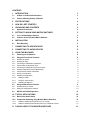
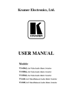
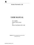
Front/Rear panel features of the CVG-606xl are shown in Figure 1. The features are described in Table 1 and
Table 2.
NOTE
For operation instructions refer to section 9.
5
Figure 1: CVG-606xl Front/Rear Panel Features
Table 1: CVG-606xl Front Panel Features
No.
1.
2.
3.
Feature
Function
Power Switch
Illuminated switch: supplies power to the unit.
OUTPUT SELECTOR Select the desired output that the input signal is switched to.
buttons
Select the desired input to be switched to the output.
INPUT SELECTOR
buttons
NOTE
Pressing input buttons "1", "2" and "3"
together resets the machine and performs a
7-segment display test.
4.
5.
6.
OUTPUT STATUS
labels
INPUT STATUS
display
RCL illuminated button
Identifies a crosspoint between each output and the input below it.
Displays the selected input switched to the output (marked above each input).
Should be pressed, followed by an input or output pushbutton to select a
predetermined setup (1-6 available setups for the CVG-606xl and 1-8 setups for
the CVG-808xl. For example, press RCL followed by INPUT 4 button to recall
Setup # 4 from the non-volatile memory.
6
No.
Feature
Function
7.
STO illuminated button
Should be pressed, followed by an input or output pushbutton to store the current
status in the non-volatile memory. For example. Press STO followed by INPUT
4 button to store Setup # 4 in the non-volatile memory.
NOTE
To delete a setup from the memory, press the
STO and RCL buttons simultaneously, followed
by the input button (Setup number) to be
deleted.
8.
AFV illuminated button
9.
AUDIO
10.
VIDEO
11.
TAKE
When pressed, illuminates and selects the "Audio Follow Video" function. If the
audio configuration differs from the video configuration, the INPUT STATUS
display flashes the audio outputs that are to be reconfigured for AFV operation. In
such case, the TAKE button must be pressed to confirm the modification.
When pressed, illuminates and selects the audio mode (Breakaway) to enable
modification of the audio crosspoints.
When pressed, illuminates and selects the video mode (Breakaway) to enable
modification of the video crosspoints.
The machines can operate either in "Take" mode or in "Normal" (no user
confirmation for each action is needed) mode. Pressing the TAKE button toggles
the mode, and the button illuminates when in "Take Mode". In "Take Mode", any
action would cause the TAKE button to blink before implementation, and the user
is required to press TAKE again in order to implement the operation.
NOTE
To cancel any operation initiated by pressing a
button, press the same button again.
12.
OFF
13.
ALL
When pressed after pushing an output button, disconnects that video/audio output
from the video/audio input. To disconnect all the outputs, press the ALL button
followed by the OFF button.
When pressed followed by an input button, connects that audio/video input to all
audio/video outputs.
Table 2: CVG-606xl Rear Panel Features
No.
1.
2.
3.
4.
5.
6.
7.
8.
Feature
1-6 AUDIO INPUTS
RCA connectors
1-6 AUDIO OUTPUTS
RCA connectors
RS-485 terminal block
EXT. SYNC BNC
connector
SYNC Select switch
VIDEO INPUTS BNC
connectors
VIDEO OUTPUTS BNC
connectors
DB-9 female RS-232
connector
Function
Audio inputs used to connect the stereo audio input sources.
Audio outputs used to connect the stereo audio output acceptors.
Used for bi-directional communication with another Matrix Switcher or PC
through RS-485 interface (see section 9.4 for more details concerning the RS485 operation).
Used for connection of an external video sync input. The external sync input
can be selected by the SYNC Select switch.
Selects either an external sync from the external source, or internal sync, which
is normally inputted via the VIDEO INPUT #1 connector (see section 9.3.1 for
more information concerning the sync selection).
Video inputs used to connect the video sources.
Video outputs used to connect the video acceptors.
Used for control of the Matrix Switcher (see section 9.4 for more details
concerning the RS-232 operation) from a PC, or remote control device, through
an RS-232 interface and a null-modem adapter (provided with the machine).
NOTE
7
No.
Feature
Function
Operation of the machine from a remote PC
may be done using the control software
(provided with the machine).
9.
Setup DIP switches
10.
Power Connector
6
INSTALLATION
6.1
Rack Mounting
Allow proper configuration of the control signals received and transmitted
through the RS-232 (or RS-485) control port, master/slave modifications, line
termination and device ID numbers.
A 3-prong AC connector allows power to be supplied to the unit. Directly
underneath this connector, a fuse holder houses the appropriate fuse.
Each of the Matrix Switchers described in this manual may be rackmounted in a standard 19” (1U) EIA rack
assembly and includes rack “ears” at the ends of the front panel. These devices do not require spacing above or
below the unit for ventilation. To rack mount any of the Matrix Switchers, simply place the unit’s rack ears
against the rack rails of the rack, and insert standard screws through each of the four corner holes in the rack
ears.
7
CONNECTING TO VIDEO DEVICES
Video sources and output devices (such as monitors, or recorders) may be connected to the Matrix Switchers
through the BNC type connectors located on the back of the unit. Bear in mind that the output signal format will
match that of the input signal format.
All signal connections that use more than one cable interconnecting between devices should be of equal length.
(Example: cables between a camera and the machine should be equal in length).
8
CONNECTING TO AUDIO DEVICES
Audio sources and output devices (such as amplifiers or recorders) may be connected to the machines through
the RCA type connectors (CVG-808XL, CVG-606XL).
9
USING THE MACHINES
9.1
Powering on the Machine
NOTES
1. The machine should only be powered on, after all connections
are completed, and all source devices have been powered on.
Do not attempt to connect or disconnect any video, audio or
control signals to the machine while it is powered on!
2. The socket-outlet should be near the equipment and should be
easily accessible. To fully disconnect equipment, remove
power cord from socket.
1.
2.
Press the toggle switch on the far left-hand side of the front panel to the ON position. The toggle switch
glows.
Operate the acceptors.
9.2 Using the Front Panel Controls
The front panels of CVG Matrix Switcher are designed to be simple to operate, and accomplish the basic
function of selecting an input source and output device.
9.2.1
Selecting an Output
Output selection on the Matrix Switchers is made by pressing any of the buttons marked “1” through “8” (CVG808XL), or "1" to "6" (CVG-606XL) on the front panel. These buttons correspond to output connections as
marked on the back panel.
8
9.2.2
Selecting an Input
Input selection on the Matrix Switchers is made by pressing any of the buttons marked “1” through “8” (CVG808XL), or "1" to "6" (CVG-606XL) on the front panel. These buttons correspond to input connections as
marked on the back panel.
9.2.3
Connecting a Video/Audio Input/Output
To connect a video/audio Input to a specific output, press the desired output button (upper line), followed by the
desired input button (lower row).
9.2.4
Disconnecting a Video/Audio Input
To disconnect a video/audio Input from a specific output, press the desired output button followed by the OFF
button. To disconnect all the outputs, press the ALL button, followed by the OFF button.
9.2.5
Connecting a Video/Audio Input to All Outputs
To connect a video/audio Input to all outputs, press the ALL button followed by the INPUT button
corresponding to the input, which is to be routed to all the outputs.
9.2.6
Selecting Video/Audio Control (Breakaway)
For audio control only, press the AUDIO button. For video control only, press the VIDEO button. Note that the
STATUS window displays audio or video settings in accordance with the selection.
9.2.7
Using the Audio Follow Video Mode
To select "Audio Follow Video" mode, press the AFV button. Note that if the audio configuration differs from
the video configuration, the differing audio outputs blink in the STATUS window of the audio display. The
AUDIO and TAKE buttons blink as well, which means that the audio configuration will be modified for AFV
operation. Press the TAKE button to confirm the modification.
9.2.8
Storing a Configuration
To store a configuration, press the STO button, followed by input or an output button to mark the setup number.
For example, press STO followed by INPUT # 3 button to store the current configuration in Setup # 3 in the
internal non-volatile memory of the switcher. To abort an operation of the STO button once it was pressed,
press it again.
9.2.9
Recalling a Configuration
To recall a configuration, press the RCL button, followed by an input or an output button, marking the setup
number. For example, press RCL followed by INPUT# 3 button to recall Setup # 3 from the internal nonvolatile memory of the switcher. To abort an operation of the RCL button once it was pressed, press it again.
9.2.10
Deleting a Setup
To delete a setup, press both the STO and the RCL buttons followed by the input button corresponding to the
setup number, which is to be deleted.
9.2.11
Using the Take Function
To activate the "Take" Function, press the TAKE button (the TAKE button illuminates). After each pressing of
the above-mentioned buttons, the TAKE button blinks together with the relevant numbers in the STATUS
display. Confirmation of the action is implemented by pressing the TAKE button again (the TAKE button then
stops blinking). If the STATUS display keeps on blinking for one minute (no button is pressed), the function
will be aborted. To abort implementing an operation in “Take” mode, press that button which originally caused
the display to blink.
9.2.12
Resetting the Machine
To reset the machine, press INPUTS buttons "1", "2" and "3" simultaneously. The machine resets itself and a 7segment self-test is automatically performed.
9.3 Using the Back Panel Controls
The switcher ID numbers, the RS-232 / RS-485 settings, and the sync source selection are all configured on the
back panel of the machine.
9
9.3.1
Selecting the Sync Source
Input sync selection is made using the "Sync Select” button located on the back panel. For an external sync
operation, press the “Sync Select” button. For an internal sync operation, release the “Sync Select” button. This
modifies the input circuitry to select the required input sync source.
9.3.2
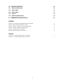
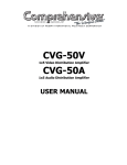
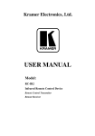
Setting the Configuration Switches
Setting the configuration switches is accomplished through a bank of DIP switches located on the back panel of
each Matrix Switcher. Table 3 describes the settings and configurations for each of the DIP switches. To set the
configuration switches, confirm that power to the Matrix Switcher is OFF, and with a small flathead
screwdriver, move the DIP switches to the "ON" or "OFF" position as shown in Table 3 and Figure 3.
Master/Slave DIP switches configure the Matrix Switcher for operation in a multiple switcher configuration. If a
Matrix Switcher is operating and being controlled independently, it should be assumed that it is operating in the
“Master” configuration.
Up to 8 Matrix Switchers may be cascaded for control via a single port by configuring one Matrix Switcher as a
"master", or ID number "1", while all the others are assigned as slave Matrix Switchers or an ID other than "1".
When RS-232 connection is implemented, DIP switch # 8 allows you to enable RS-232 communication
between the Matrix Switcher and the PC. This is desirable, so that the controlling device “knows” that the
controlled device has carried out its instructions. When RS-485 connection is used for communication between
the Matrix Switcher and the PC, DIP switch # 8 should be up ("OFF"). In some applications, it may be
desirable for some machines not to reply to instructions received on the RS-232 and RS-485 ports. In this
scenario, you would disable the “Reply”, or acknowledgement commands. DIP switch # 5 enables or disables
"reply" from the Matrix Switcher to the PC.
In the case of interconnection between more than two RS-485 receivers-transmitters (including PC), the
termination resistor must be disconnected on all the devices, except the first and last machines on the
communication line. DIP switch # 4 connects or disconnects the termination resistor.
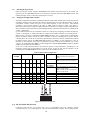
Table 3: DIP Switches Configuration
MACHINE
NUMBER
SELF ADDRESS
DIP SWITCH
DIP switch #4
2
1
0
3
2
1
DIP switch #5
1. (Master)
0
0
0
ON
ON
ON
2.
0
0
1
ON
ON
OFF
DIP switch #6,
DIP switch #7
DIP switch #8
3.
4.
5.
6.
7.
8.
0
1
0
ON
OFF
ON
0
1
1
ON
OFF
OFF
1
0
0
OFF
ON
ON
1
0
1
OFF
ON
OFF
1
1
0
OFF
OFF
ON
1
1
1
OFF
OFF
OFF
"ON"= Connects the termination resistor.
"OFF"= Disconnects the termination
resistor.
"ON"= Enables reply from switcher to PC.
"OFF"= Disables reply from switcher to
PC.
Not used
"ON"= Enables RS-232 communication
between switcher and PC.
"OFF"= Enables RS-485 communication
between switcher and PC.
Figure 2: DIP switches General View
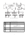
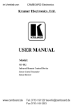
9.4 RS-232 and RS-485 Operation
Connections made between your switcher and a PC are accomplished using your computer’s RS-232
communication port, or by connecting the PC to the RS-485 terminal block connector. Bear in mind that serial
10
communication between Matrix Switchers is always via RS-485 (see example in Figure 5). The RS-232 port is
either a DB-9 (9-pin port) or DB-25 (25-pin port). The cable connecting your switcher to the PC should be
wired as shown in Figure 4. A 9-25 pin adapter or 9-9 pin null-modem adapter is included for your convenience.
The null-modem adaptor is wired as shown in Figure 4. If using the adaptor (recommended), plug it into the
PC’s serial port, and connect via a flat-cable from the other end of the adaptor to your switcher. Please keep in
mind that it is not recommended to extend an RS-232 signal beyond a length of 30 feet, without the use of an
RS-232 to RS-422 converter at both the PC and the switcher.
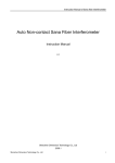
If five machines and a PC are cascaded together for example, using RS-485 interconnection, disconnect the
termination resistors on all machines except the fifth (see Figure 6). For similar setup, without a PC connected
on the RS-485 line, disconnect all resistors except for the first and fifth machines.
Figure 3: RS-232 Control Connector Wiring
Figure 4: RS-232 and RS-485 Operation
Figure 5: Terminating the Line
11
10
TYPICAL APPLICATIONS
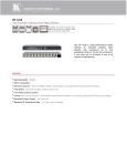
10.1 Basic Video-Audio Setup
One of the most common video formats is composite video. Figure 7 describes a typical composite video setup
using the CVG-808XL in this case. Three video-audio sources, three video-audio acceptors, and a genlock
source are connected to the machine, while control of the Matrix Switcher is implemented via the PC using RS232 communication.
Perform the following steps (as necessary):
1.
2.
3.
4.
Connect all video-audio sources to the video-audio inputs of the Matrix Switcher.
Connect all video-audio acceptors to the video-audio outputs of the Matrix Switcher.
Operate the Matrix Switcher, PC sources and acceptors.
Select the required video input to be switched, using front panel input selector pushbuttons (or the software
program controls).
Figure 6: Basic Video-Audio Setup
10.2 Component Switching using Multiple Matrix Switchers
A commonly used video format is component video, and switching the three signals (components)
simultaneously is sometimes a complicated task. Using several Matrix Switchers, however, this can be done
very easily and efficiently. This is done by dedicating each switcher to a single component.
For example, for an 8 input, 8 output RGBS matrix switcher, 4 CVG-808xl’s would be used – one for the Red
component, one for Green, one for Blue, and one for Sync. Each component of the RGBS signal is then
connected to the same input (or output) number on the switcher. For example, the first RGBS source is
connected to Input #1 on the 4 switchers, the second is connected to Input #2 on the switchers, etc. The
switchers are configured to mirror each other, so the input to output connections are identical on all 4 machines!
In order to switch during the vertical interval when working in this way, the switchers should be configured for
operation using the “Ext. Sync”. A sync source should then be connected to all the machines (for RGB this
could be the Green channel, and for YUV this could be the Y channel).
12
The examples below detail the building of RGB matrices. The same principles may be used for YC (2
switchers), YUV (3 switchers), RGBS (4 switchers), and RGBHV (5 switchers).
10.2.1
RGB/YUV Switching with RS-232 (e.g. PC Control)
For RS-232 control of the component matrix switcher, an additional piece of equipment would be required.
Since RS-232 can only be used for control between 2 pieces of equipment (e.g. a PC and a switcher), we need a
method of “distributing” the RS-232 to all 3 machines. The CVG-14 “RS-232 Port Extender” is designed for
this purpose.
Perform the following steps (as necessary):
1. Connect the RGB sources to the VIDEO INPUTS connectors of the Matrix Switchers, connecting the “R”
components to Matrix Switcher #1, “G” to #2, and “B” to #3. Make sure that each component of a video
source is connected to the same input number on the three switchers.
2. Similarly, connect the RGB acceptors to the VIDEO OUTPUTS connectors of Matrix Switchers #1 to #3.
3. If the video sources are synchronized, and vertical interval switching is desired, connect sync sources to all
3 machines, and select to work with “Ext. Sync” (selector switch pressed in).
4. Assign all 3 machines as machine number #1 (see Table 3: “DIP Switches Configuration" for more
information).
5. Set DIP switch #5 (Reply) of the first machine to "ON". Set to "OFF" for the other machines.
6. Set DIP switch #8 of all the machines to "ON" (RS-232 communication between switchers and external
controller).
7. Connect the serial port of the PC to a port on the CVG-14, and connect each switcher to a CVG-14 port.
Configure the DIP-switches of the CVG-14 for the 4 ports which were connected.
8. Operate the Matrix Switchers, PC, CVG-14, RGB sources and RGB acceptors
9. The inputs can now be switched to the outputs. This is done via the front panel switches of the first
switcher, and/or via the PC.
10.2.2
RGB/YUV Switching with RS-485 Control (or no External Control)
Communication between the switchers is implemented via RS-485, which could also be extended to an external
controller.
Perform the following steps (as necessary):
1. Repeat steps 1-3 of section 10.2.1.
2. Connect the RS-485 terminal block connectors of all the Matrix Switchers in parallel using RS-485 cable,
and connect to also an external controller if required.
3. Assign all the machines with the same machine number - but NOT machine #1 - using the DIP switches
located at the back of the machine, (as described in Table 3: “DIP Switches Configuration").
4. NOTE: The machines are all assigned as slaves having the same machine number. A master machine is
not assigned.
5. Set DIP switch #4 (RS-485 termination) of the third machine to "ON" and of the second machine to
"OFF". If an RS-485 external controller is connected, then DIP switch #4 of the first machine should be set
to "OFF"; if no external controller is used, set this switch to "ON".
6. Set DIP switch #5 (Reply) of the first machine to "ON". Set to "OFF" for the other machines.
7. Operate the Matrix Switchers, controller (if used), RGB sources and RGB acceptors.
8. The inputs can now be switched to the outputs. This is done via the front panel switches of the first
switcher, and/or via the external controller.
11
TAKING CARE OF YOUR MATRIX SWITCHER
Do not locate your Matrix Switcher in an environment where it is susceptible to dust or moisture. Both of these
may damage the electronics, and cause erratic operation or failure. Do not locate your Matrix Switcher where
temperature and humidity may be excessive. Doing so may also damage the electronics, and cause erratic
operation or failure of your Matrix Switcher. Do not clean your Matrix Switcher with abrasives or strong
cleaners. Doing so may remove or damage the finish, or may allow moisture to build up. Take care not to allow
dust or particles to build up inside unused or open connectors.
13
12
TROUBLESHOOTING
1.
2.
NOTES
Please note that if the output signal is disturbed or
interrupted by very strong external electromagnetic
interference, it should return and stabilize when such
interference ends. If not, turn the power switch off and on
again to reset the machine.
If the recommended actions still do not result in satisfactory
operation, please consult your CVG Dealer.
12.1 Power and Indicators
Problem
Remedy
No power
1.
2.
3.
Confirm that the rocker switch is in the “ON” position, and that the lamp is
illuminated.
Confirm that power connections are secured at the machine and at the
receptacle. Make sure the receptacle is active, outputting the proper mains
voltage.
If there is still no power, check the fuse. Remove power cord from the AC
outlet and from the machine and then, using a flat screwdriver, remove the
fuse holder located directly below the power connector. Confirm that the fuse
is good by looking at the wire connected to the ends of the fuse. If the wire is
broken, replace the fuse.
12.2 Video Signal
Problem
Remedy
No video at the output
device, regardless of input
selected.
1.
2.
3.
Video level is too high or
too dim.
1.
2.
Confirm that your sources and output device are powered on and connected
properly. Video signals connected to the input of your machine should be of an
identical signal format at the output of your source. Video signals at the output
of your machine should be of an identical signal format as at the input of your
display or recorder.
Confirm that any other switchers in the signal path have the proper input
and/or output selected.
Use the Video Tester to test the video path leading to/from your Matrix
Switcher (see section 4.1 " Video Tester")
Verify that the video line is well matched through 75ohm impedance,
otherwise it results in a video level that is too high or too dim when looping is
performed and the termination switches are not in proper position.
Confirm that the connecting cables are of high quality, properly built and
terminated with 75ohm BNC connectors. Check level controls located on your
source input device or output display or recorder.
14
Problem
Remedy
Noise bars are "rolling" up
or down in the output
image
or:
Low Frequency Hum in
the audio output
Hum bars (ground loop) are caused by a difference in the ground potential
of any two or more devices connected to your signal path. This difference
is compensated by passing that voltage difference through any available
interconnection, including your video cables.
WARNING!
Do not disconnect the ground from any piece of
video equipment in your signal path!
Check the following to remove hum bars:
1. Confirm that all interconnected equipment is connected to the same phase of
power, if possible.
2. Remove equipment connected to that phase that may introduce noise, such as
motors, generators, etc.
3. Disconnect all interconnect cables and reconnect them one at a time until the
ground loop reappears. Disconnect the affected cable and replace, or insert an
isolation transformer in the signal path.
12.3 Audio Signal
Problem
Remedy
No audio at the output
device, regardless of input
selected
1.
2.
Audio level is too low
1.
2.
Confirm that your sources and output device are powered on and connected
properly. Audio signals connected to the input of your machine should be
properly wired to the output of your source. Audio signals connected to the
output of your machine should be properly wired to the input of your machine
or recorder.
Confirm that any other amplifiers in the signal path have the proper input
and/or output selected. Pay special attention to input amplifiers that may be
built into your acceptor.
Confirm that the connecting cables are of high quality and properly built. Take
special care in noting the wiring configuration of balanced to unbalanced
cables.
Check level controls located on your source input device or output display or
recorder.
12.4 Control
Problem
Remedy
No control of Matrix
Switcher from PC
software
1.
2.
3.
4.
5.
6.
Confirm the wiring of the connecting cable. This pin configuration may be found in
Figure 4. Cable length should not exceed 25 feet.
Confirm that all DIP switches on the Matrix Switcher have been set properly. Keep
in mind that if you are only controlling one Matrix Switcher on a specific port, that
Matrix Switcher must be assigned the ID of “1”.
Confirm that the baud rate of your computer COM port is set to the same as that of
your Matrix Switcher (9600-Baud). Confirm that the proper COM port is selected in
the control software.
Confirm that bi-directional communication is enabled on all Matrix Switchers.
Please refer to Section 9.3.2 "Setting the Configuration Switches" for proper
configuration for your Matrix Switcher.
With custom software, do not send multiple commands at the same time. The Matrix
Switcher must complete one command and send the reply, before receiving another.
Confirm that the computer you are using supports true RS-232C protocol.
Computers such as the Apple Macintosh do not!
15
12.5 Switching Malfunctions
Problem
Remedy
The switcher succeeds
in switching a number
of sources then fails to
switch one.
Malfunction in the particular source or cable assembly.
NOTE
The most common failure mode in transferring the signal of
an audio source is a break in the connecting wire.
Disconnect the source from a channel that is switching successfully and connect the
suspect source to it. If the channel continues to switch successfully, then there is
something wrong with the Matrix Switcher or the suspect source was not connected
properly. If it does not continue to switch successfully, then there is something wrong
with the source or cable assembly. Check them.
The Matrix Switcher
turns ON but will not
switch at all
13
One of the two flat cables leading from the main board to the control board may be
disconnected and the switch command is not being transferred to the Matrix
Switcher. Check them.
COMMUNICATION PROTOCOL
Communication with the Matrix Switchers described in this manual uses four bytes of information as defined
below. Data is transferred at 9600 baud with no parity, 8 data bits and 1 stop bit.
1st byte
0
7
MSB
DESTINATION
D
6
INSTRUCTION
N3
N2
3
2
N5
5
N4
4
0
6
0
5
0
4
I3
3
0
6
0
5
0
4
O3
3
0
6
0
5
0
4
0
3
N1
1
N0
0
LSB
2nd byte
INPUT
1
7
3rd byte
OUTPUT
1
7
4th byte
1
7
MACHINE NUMBER
M2
M1
2
1
1st BYTE: Bit 7 – Defined as "0",
D – “DESTINATION BIT”
This bit is always "low", when sending from the PC to the Matrix Switchers, and "high" for information sent to
the PC.
N5…N0 – “INSTRUCTION”.
The function that is to be performed by the Matrix Switcher (s) is defined by these 6 bits. Similarly, if a function
is performed via the machine’s keyboard, then these bits are set with the INSTRUCTION NO. which was
performed. The instruction codes are defined according to the table below (INSTRUCTION NO. is the value to
be set for N5…N0).
2nd BYTE:
Bit 7 – Defined as "1".
Bits 4 – 6 - Defined as "0".
I3… I0 – “INPUT”.
When switching via RS-232 for RS- 485 (for instruction codes 1 and 2), these bits set the input that is to be
switched. Similarly, if switching is done via the machine’s keyboard, then these bits are set with the input
16
number which was switched. For disconnect, set as 0. For other operations, these bits are defined according to
the table.
3rd BYTE:
Bit 7 - Defined as "1".
Bits 4-6 Defined as "0".
O3 – O0 – “OUTPUT”.
When switching via RS-232 or RS-485 (for instruction codes 1 and 2), the output to switch is set by these bits.
Similarly, if switching is done via the machine’s keyboard, then these bits are set with the output number which
was switched. For other operations, these bits are defined according to the table.
4th BYTE:
Bit 7 – Defined as "1".
Bits 3-6 Defined as "0".
M2… M0 – “Machine Number”.
Machine Number = (DIP – Switch Code) + 1.
INSTRUCTION
#
0
1
DESCRIPTION
RESET MACHINE
SWITCH VIDEO
DEFINITION FOR SPECIFIC INSTRUCTION
INPUT
0
Set equal to video input to be
switched
Set equal to audio input to be
switched
Set as SETUP #(1-8) or (1-6 for
the CVG-606XL)
OUTPUT
0
Set equal to video output to be
switched (0=to all the outputs)
2
SWITCH AUDIO
Set equal to audio output to be
switched (0=to all the outputs)
- To store parameters
3
STORE STATUS
- to delete setup
4
RECALL STATUS
Set as SETUP #(1-8) or (1-6 for Don’t care
the CVG-606XL)
5
REQUEST STATUS OF A
Set as SETUP #(1-8) or (1-6 for Equal to output number whose
VIDEO OUTPUT
the CVG-606XL)
status is read
6
REQUEST STATUS OF AN Set as SETUP #(1-8) or (1-6 for Equal to output number whose
status is read
AUDIO OUTPUT
the CVG-606XL)
7
VIS SETTING
Don’t care
- for immediate switching
- for VIS switching
8
BREAKAWAY SETTING
Don’t care
- for audio-follow-video
- for breakaway
9
NOT USED
10
REQUEST VIS SETTING
Set as SETUP #(1-8) or (1-6 for Don’t care
the CVG-606XL)
11
REQUEST BREAKAWAY Set as SETUP #(1-8) or (1-6 for Don’t care
SETTING
the CVG-606XL)
12 to 14 NOT USED
15
REQUEST WHETHER
Set as SETUP #(1-8) or (1-6 for Don’t care
SETUP IS DEFINED
the CVG-606XL)
16
ERROR/BUSY
Don’t care
Don’t care
17
RESERVED
18
RESET MACHINE
0
0
19
STORE STATUS
Set as SETUP #(1-8) or (1-6 for 0-to store parameters
the CVG-606XL)
1-to delete setup
20
RECALL STATUS
Set as SETUP #(1-8) or (1-6 for Don’t care
the CVG-606XL)
21 to 56 NOT USED
57
SET AUTO-SAVE
for auto save
Don’t care
0 – no save
58 to 60 RESERVED
61
IDENTIFY MACHINE
1or 2 – machine name
Don’t care
3 or 4 – version
17
NOTE
1
2
2
2,7
2,7
3,7
3,7
2
2
3,7
3,7
4
5
6
1
2,7,9
2,7,10
8,2
11
NOTES ON THE ABOVE TABLE:
NOTE 1 - When the master switcher is reset, (e.g. when it is turned on), the reset code is sent to the PC. If this code is sent
to the switchers, it will reset according to the present power down settings.
NOTE 2 - These are bi-directional definitions. That is, if the switcher receives the code, it performs the instruction, and if
the instruction is performed (due to a keystroke on the front panel), then these codes are sent. For example:
0000 0001
1000 0101
1000 1000
0011
was sent from the PC, then the switcher (machine # 3) will switch input 5 to output 8. If the user switched input # 1 to output
# 7 via the front panel keypad, then the switcher will send:
0100 0001
1000 0001
1000 0111
1000 0011
⇒ to the PC.
When the PC sends one of the commands in this group to the switcher, then, if the instruction is valid, the switcher replies by
sending to the PC the same four bytes that it sent (except for the first byte, where the DESTINATION bit is set "high").
NOTE 3 - The reply to a "REQUEST" instruction is as follows: the same instruction and INPUT codes as were sent are
returned, and the OUTPUT is assigned the value of the requested parameter. The replies to instructions 10 and 11 are as per
the definitions in instructions 7 and 8 respectively. For example, if the present status of machine number # 5 is breakaway
setting, then the reply to
0000 1011
1000 0001
1000 0000
1000 0101
Would be ⇒
0100 1100
1000 0001
1000 0001
1000 0101
NOTE 4-The reply to the "REQUEST WHETHER SETUP IS DEFINED" is as in TYPE 3 above, except that here the
OUTPUT is assigned with the value 0 if the setup is not defined; or 1 if it is defined.
NOTE 5-An error code is returned to the PC if an invalid code was sent to the switcher (e.g. trying to save to a setup greater
than 8, or trying to switch an input or output greater than the highest one defined). This code is also returned to the PC if an
RS-232 instruction is sent while the machine is being programmed via the front panel. Reception of this code by the switcher
is not valid.
NOTE 6–This code is reserved for internal use.
NOTE 7-SETUP #0 is the present setting. SETUP #1 to SETUP# 8 are the settings saved in the switcher's memory, (i.e.
those used for Store and Recall).
NOTE 8-Under normal conditions, the machine's present status is saved each time a change is made. The "power-down"
save (auto-save) may be disabled using this code. Note that whenever the machine is turned on, auto-save function is set.
NOTE 9–This is identical to instruction 3 (machine uses instruction 3, when sending to PC).
NOTE 10–This is identical to instruction 4 (machine uses instruction 4, when sending to PC).
NOTE 11-This is a request to identify the switcher/s in the system. If the INPUT is set as 1 or 2, the machine will send its
name. The reply is the decimal value of the INPUT and OUTPUT. For example, the reply to the request to send machine
name (for machine number 001) would be:
0111 1101
1000 1000 (i.e. 128 + 8)
1000 1000 (i.e. 128 + 8)
1000 0001
If the request for identification is sent with the INPUT set as 3 or 4, the appropriate machine will send its software version
number. Again, the reply would be the decimal value of the INPUT and OUTPUT - the INPUT representing the number in
front of the decimal point, and the OUTPUT representing the number after it.
For example, for version 3.5, the reply would be:
0111 1101
1000 0011 (i.e. 128 + 3)
1000 0101 (i.e. 128 + 5)
1000 0001
18
TABLE OF HEX CODES FOR THE MASTER CVG-808xl
The table below shows the “HEX” codes for switching the master CVG-808xl.
The table is also valid for the CVG-606xl if the last two rows and columns are ignored.
OUT 1 OUT 2 OUT 3 OUT 4 OUT 5 OUT 6 OUT 7 OUT 8
IN 1
IN 2
IN 3
IN 4
IN 5
IN 6
IN 7
IN 8
01
81
81
81
01
82
81
81
01
83
81
81
01
84
81
81
01
85
81
81
01
86
81
81
01
87
81
81
01
88
81
81
01
81
82
81
01
82
82
81
01
83
82
81
01
84
82
81
01
85
82
81
01
86
82
81
01
87
82
81
01
88
82
81
01
81
83
81
01
82
83
81
01
83
83
81
01
84
83
81
01
85
83
81
01
86
83
81
01
87
83
81
01
88
83
81
01
81
84
81
01
82
84
81
01
83
84
81
01
84
84
81
01
85
84
81
01
86
84
81
01
87
84
81
01
88
84
81
01
81
85
81
01
82
85
81
01
83
85
81
01
84
85
81
01
85
85
81
01
86
85
81
01
87
85
81
01
88
85
81
For Technical Support, contact us at:
Comprehensive Video Group
55 Ruta Court
South Hackensack, NJ 07606
800-526-0242
e-mail:[email protected]
www.comprehensivevideo.com
19
01
81
86
81
01
82
86
81
01
83
86
81
01
84
86
81
01
85
86
81
01
86
86
81
01
87
86
81
01
88
86
81
01
81
87
81
01
82
87
81
01
83
87
81
01
84
87
81
01
85
87
81
01
86
87
81
01
87
87
81
01
88
87
81
01
81
88
81
01
82
88
81
01
83
88
81
01
84
88
81
01
85
88
81
01
86
88
81
01
87
88
81
01
88
88
81