1
284-9904-00
2004/1 (AB-C)
English
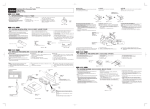
Remove the stopper following the procedures below when this source unit is installed
without the universal mounting bracket.
!"!#$%&'()*+#,-./*012345678
!"#$%&'(
■ !
= = !==
!K
=
=
=
=
== !=
= !===== !K
=
1
! / 1. This set is exclusively for use in cars with a
negative ground, 12 V power supply.
1. !"#$%&'12V
2. Read these instructions carefully.
2. !"#$%&'
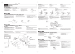
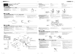
3. Be sure to disconnect the battery “v” terminal
before starting. This is to prevent short circuits
during installation. (Figure 1)
3. !"#$%&'()v
!"#$%&'(1F
1. = =12VI=åÉÖ~íáîÉ=ÖêçìåÇ=
== = !"K
!"#$%
2. =
!"#===
2
!"#K
3. != = !=“v”= =
!K= = = = !=
= K=E=1F
!"#
Car battery
డӡԄ
차 배터리
■ Fixed Mount (Using the bracket originally equipped in vehicle)
This unit is designed for fixed installation in the dashboard.
If the vehicle is equipped with a factory-installed radio, install the source unit with the
parts and screws marked (★). (Figure 8)
If the vehicle is not equipped with a factory-installed radio, obtain an installation kit to
install the source unit in the following procedure.
1. Secure the mounting brackets to the chassis as shown in Figure 8. When the
source unit is installed without the universal mounting bracket, holes exist;
modification, such as drilling new holes, of the mounting brackets may be required
for other models.
Figure 1 / 1 / 1
!
Push in the protruding part as shown in the figure.
1. BEFORE STARTING / English
■ ■ PRECAUTION
Installation/Wire Connection Guide
!
/
/
==
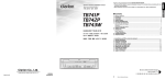
2. CAUTIONS ON INSTALLATION / 1. Prepare all articles necessary for installing the source unit before
starting.
2. Install the unit within 30° of the horizontal plane. (Figure 2)
3. If you have to do any work on the car body, such as drilling holes,
consult your car dealer beforehand.
!"#$% / = !
■ !
!E
'ISO/DN
E !"#$%&'
F
!"#$%&'()*+
!"#$%&'(")*+,-./0123EGF !"#$%&'%()
8
!"#$%&'(#)*+,-./0(#12345678(#,9#:;
1. U !"#$%&'()*+,(-./0/"#$%12345"67
!"#$%&'()*+,-./012%3456789':(
2. 6 !"#$
3. !"#$%&'()*+,-.
%&'/01'2
2. E=6F=
2. Wire as shown in Installation (Section 6).
1. !"#$%&'()*(+,-./0123
1. !==
2. !"#$%&'()*+,-30° E2F
2. 3. !"#$%&'()*+,-.,/01#234567
4. !"#$%&'()*
3. = ====
= !"#K
+,$%-./012*E3F
=
= !=30°=
=
3. !=
===
=
K
= !=I= !==
== !"#K
3. Secure the unit in the dashboard, and then reassemble the dashboard and the
center panel.
== !"#K
= !"#K=E=2F
=
=I=
4. = = != !"#K==
= === !K=E=3F
4. Use the enclosed screws for installation. Using other screws can
cause damage. (Figure 3)
=E
!
F
■ ==
=E
=E
!== !
!== = !
!==
F
== !== = = = !"K=== =
= = !I===EF== = = = !"#K
E8F
= = != !== !I== = = ==
= = !"#K
1. =U===== != = !"#K== =
== = =I= === X=== !
I== ==== != = == !K
==
= !=
★
★
★
Chassis / ֿஔ / 차대
Chassis / ֿஔ / 차대
Damage / ෬ߑ / 손상
★
Max. 30˚ / ቒս 30˚ / 최대 30˚
★
★
Max. 8 mm / ቒս 8 mm / 최대 8 mm
Figure 2 / 2 / 2
English
Figure 3 / 3 / 3
∗ : The parts and SCREW with this mark are used to install radio or included in the
installation kit.
★ : The screws with this mark are originally attached to the vehicle.
Note 1: In some cases, the center panel may require some modification (trimming, filling,
etc.).
Note 2: If a hook on the installation bracket interferes with the unit, bend and flatten it
with a nipper or a similar tool.
3. INSTALLING THE SOURCE UNIT / !" / ==
■ Universal Mount
■ !"#
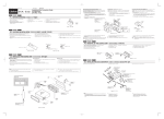
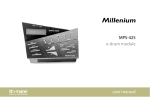
1. Place the universal mounting bracket into the instrument panel, use a
screwdriver to bend each stopper of the universal mounting bracket
inward, then secure the stopper as shown in Figure 4.
1. 2. Wire as shown in Section 6.
3. Insert the source unit into the universal mounting bracket until it locks.
4. Take care of the top and bottom of the outer escutcheon and mount it
so that all the hooks are locked.
!"#$%&'()*+ ,-.
!"#$%&'4 !"#$%
2. 6
English
■ =
!"#$/0123
!"#$
1. = = != ==I= !"==
!= !== != !==4==
= != !"#K
2. =6=
3. !"#$%&!'()*+,-./
4. !"#$%&'(&)*+,-.$/012345
3. ===
== !==
4. = !==
K
=
K
== != !
∗ : = = = = = = = !I== = !
!K
★ : = = = = != != !== !K
=1 : = == == = = !K=EI==F
=2 : = === = =I= == = !=
= !K
4. REMOVAL OF THE SOURCE UNIT / 1. When removing the source unit, disassemble it in the reverse of the order in
Section “3. INSTALLING THE SOURCE UNIT”.
2. Remove the Detachable Control Panel (DCP).
∗ For instructions on removing the DCP, refer to the owner’s manual.
= !K
= !=
∗ : !"#$%&'()*+,-./012*+3456
★ : !"#$%&'()"*
1
!"#$%&'()* !E !"#F
2
!"#$%&'()*!+ !"#$%&'()*+,-.
!"# / ==
1. !"#$%&'()33. !"#$%&'()*+,
1. 2. !"#$%EDCPF
∗ !"#$%EDCPF
2. = =EDCPF= !"K
∗ DCP= == == != !"#K
!"#$%&'()*
= =I==“3. =”== != !"#K
3. !"#$%&'()* 9
3. = != !=
3. Press the outer escutcheon upward and remove it. (Figure 9)
4. !"#$%&= 10
4. =
4. Insert and lock the hook plates. (Figure 10)
5. !"#$%&'()*
5. = !"=
!"==
= !"K=E 9F
!K=E 10F
= !"K
=
5. Pull the hook plates to remove the source unit.
Notes:
1) Some car models require special mounting kits for proper
installation. Consult your Clarion dealer for details.
2) Fasten the front stopper securely to prevent the source unit from
coming loose.
1) !"#$%&'()*+,-.&/012345Clarion
!"
2) !"#$%&'()*"+
• Console opening dimensions
• ६ᇌขा५ԋձ
• 콘솔 입구 크기
Hole
ा५
홀
W
1) = =I= = = = == =
== !K= ==`ä~êáçå= = !"#K
2) =
!K
!==
!=
=
!"==
English
Instrument panel
ၕѝϷ
계기반
5. CAUTIONS ON WIRING / 7-3/16"
(182 mm)
!"#$% / !
!== !
Hole
ा५
홀
2. Be particularly careful where you route the wires. Keep them well away from the
engine, exhaust pipe, etc. Heat may damage the wires.
Stoppers
ᇌఝ
스토퍼
53 mm
2-1/8"
■ 1. Be sure to turn the power off when wiring.
Hexagonal bolt
࢟ઋඤ
육각형 볼트
Strap
༵๏
스트랩
* This part is not provided in some models.
* Օਲ਼ࡸᄤႼཻࠖྟેႼ܉è
* 이 부품은 일부 모델에는 제공되지 않습니다.
Top
ҍ
위
Screwdriver
ઋර֞
드라이버
Installation direction
τሔ١ས
설치 방향
Universal mounting bracket
Ⴏሔᆭࡖ
일반 탑재용 받침대
Source Unit
ႂჾሔᇉ
본체
Spring
֗ߥ
스프링
Stoppers
ᇌఝ
스토퍼
Bottom
ֿҍ
아래
Outer escutcheon side view
ບআҮ൱
외부 프레임을 옆에서 본 그림
Outer escutcheon
ບআ
외부 프레임
Figure 4 / 4 / == 4
Note:
Before attaching the universal mounting bracket, slightly bend
the spring toward the inside with your fingers and attach it to the
side of car.
ሆĈ
τሔႯሔᆭࡖᆴఴƗ౯Ⴏ൴ᆾࢃ֗ߥഔསୄҮຜƗࢃఊτሔ
ᄤడӡ၉Үè
주:
일반 탑재용 받침대를 부착시키기 전에, 스프링을 손가락으로
약간 안쪽으로 구부린 다음 차 쪽으로 부착시키십시오.
3. If the fuse should blow, check that the wiring is correct.
If it is, replace the fuse with a new one with the same amperage rating as the
original one. (Figure 11)
Note:
There are various types of fuse holder. Do not let the battery side touch other metal
parts.
4. Connect the CeNET extension cable fully and securely until it locks. When the
CeNET extension cable is pulled, hold the slide cap part and pull it towards you.
∗ When the CeNET extension cable is extended or branches, use extension cable
CCA-520 (2.5m) or CCA-521 (0.6m), or Y-adapter CCA-519 (each of them is sold
separately).
∗ Use the CeNET extension cable made by Clarion.
5. When the main power supply fuse in the car is 15 A or less, purchase an
automotive cable that can withstand 15 A and supply this unit with power directly
from the battery to ensure that the unit will operate normally.
Note that a fuse must be installed at a distance no longer than 30 cm from the cable
battery terminal to prevent accidents.
6. Insert the gray connector securely into the digital signal output connector until it
locks. (Figure 12)
When disconnecting a optical digital cable, squeeze the tabs at the right and left
sides of the connector, and pull gently. (Figure 13)
Note:
The optical digital cable should not be bent with a gentle arc radius of 1.5 cm or
less. If it is bent sharper than this, the performance of the cable will be greatly
reduced and the cable may be damaged.
■ 1. 2. ■ 1. !"#$%&'
!"#$%&'()$*+,-./0123'456789)$'
PK== !"#$%&'()*+,-./
!"#$%&'()*+,-./0123456+,-789E=NNF
!"#$%&'()*+,-./012%3456789:;<=*
4. !"`Ékbq !"#$%&'()`Ékbq !"#$%&'()*
!"#$%&
* CeNET !"#$%&'()*+ !CCA-5202.5 CCA-521
0.6 !v !CCA-519 !"#$
* Clarion CeNET !"
5. !"#$%&'()#*+,-./NR !"#$%&'()*+,NR
!"#$%&'()*)+ !",-./012%&'345678
!"#$%&'()!*+,-./0PM !"#$I !"#$%
6. !"#$%&'()*+,-."#$/0123415678=NO
!"#$%&'()*+,-./01234(567789:;<=NP
!"#$%&'()*+,-./NKRÅã
!"##$%&'()*+ ,-.
!"#$%&'()*+,-
===
=
== !K
2. !== == = !"K= !=I= = !
= = ==I=== == == !K
PK = =I= = == = !"#K
= = I= = == = !==
!K=E=11F
W
= ==
= = !K
= !K= !==
=
===
4. CeNET== != = == != !"= K
CeNET== = = I= !== == !=
K
∗ CeNET== !=== === !=CCA-520 (2.5m)
=CCA-521 (0.6m) =Y- =CCA-519= = !=E=FK
∗ `ä~êáçå=`Ékbq== != !"#K
5. !==== =NR^= =I=== =NR^
==== !"==== = === =
= != !K
= == = = = = !"=PM=Åã= =
= !"= == !"#K
6. = != === !=== !"= K=E
=NOF
= = != == = = = == !
== !K=E=NPF
W
= = != = =NKRÅã= = = !"= !K
=== != =I= != == != == !K
English
6. WIRE CONNECTIONS / / ■ Attaching the Ferrite Core
■ !"#$
■ !
!== =
= != == !"= !"#K
1. Ferrite core (gray) for RCA pin cable (AUX input, 2-ZONE output)
(Figure 14).
NK RCA
14
NK RCA==
E=14FK
Attach the provided ferrite cores in the specified positions.
Note:
Be sure to check the thickness of the RCA pin cable when attaching the ferrite core.
If the cable is too thick, it may not fit in the groove in the ferrite core.
2. Ferrite core (gray) for RCA pin cable (front, rear and subwoofer
output) (Figure 15).
!"#$%&'($)*+,-./!01*=
!"#$%&'()RCA
!"#$%&'()*
!"#$%&
'"()*
OK RCA !"#$%#&'()*+,-./01234
!==15
3. Ferrite core (white) for Ce-NET cable (Figure 15).
∗ The gray ferrite core for 1 and 2 are the same item.
English
!"#$%&'!()*+,-
PK Ce-NET !"#$%&'()==15
∗ NO !"#$%&'()*+
EAUX I=2-=F=
!=EF
W
!= = !"=o`^== != = =
!K= == = != ====
=== !K
OK RCA== EI=I=
F=E=15FK
!=F=
!=E
PK `ÉJkbq= !"= !=EF=E=15FK
∗ 1=2== != = = !"K
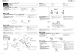
7. SYSTEM EXAMPLE / / =
■ Example of the system using an external amplifier (Audio Visual)
■ !"#$%&'()*+,-./01
■ ==
==
== !
!== =E
=E
==F
8
9
4
2
%
1
4
5
0
!
Note:
Use a CeNET extension cable that is less than 20 m in length. (including the Y-adapter CCA-519.)
:
!"20 mCeNET !"#$v CCA-519
:
=20 m= =CeNET== != !"#K=Ev =CCA-519=F
@
3
Amp
Amp
#
$
∗ This source unit can control a total of 2 changers except 2 DVD changers exist in the system.
∗ !"#2DVD !" #$%&2 !"
∗ = = != !=2=DVD= ==2= != == !K
6
7
English
1
2
3
4
5
6
7
8
9
0
!
@
#
$
%
Source unit
CeNET extension cable
CD changer
RCA extension cable (sold separately)
4-Channel power amplifier
Front speakers
Rear speakers
Monitor
TV tuner module
5.1ch surround decoder
5.1ch surround decoder control unit
Optical connector cable
Center speaker (with amplifier)
Subwoofer (with amplifier)
External unit
English
1
2
3
4
5
6
7
8
9
0
!
@
#
$
%
!
CeNET !
CD
RCA !"#$%
4 !"#$
!"
!"
TV !"
5.1 !"#$
5.1 !"#$%&'(
!"#$%
!"#$%&"'
!"#$%&'#(
!
1
2
3
4
5
6
7
8
9
0
!
@
#
$
%
CeNET =
CD RCA = =E=F
4-==
=
=
TV =
5.1= !=
5.1= != = =
= =
= =EF
!=EF
=
8. GENERAL CAUTIONS / 1. Do not open the case. There are no user serviceable parts inside. If
you drop anything into the unit during installation, consult your dealer
or an authorized CLARION service center.
2. Use a soft, dry cloth to clean the case. Never use hard cloth, thinner,
benzen, alcohol, etc. For tough dirt, apply a little cold or warm water
to a soft cloth and wipe off the dirt gentry.
IMPORTANT:
Improper installation may cause damage to your unit or car. If you do
not have the appropriate experience, consult a qualified installer.
Cutting chassis wire leads voids the warranty.
!"# / !
!== !
NK !"#$%&'()*+,-./0&1$23456789
!"#$%&'()*+,CLARION !"#$%&
OK !"#$%&'()*+,#-./0-123456(7
!"#$%&'()*+,-.,//012
!"#$%&'()*+,-./0123456789:
!"#$%&'()*+,-./01%
NK !== !K= !"= !=== =
!K= != = !"=I= = !"=
=CLARION== = = !"#K
OK != !== !=== !"#K=
=I=I==== != !K= !"
!I== !"= ==== ==
= !K
W
W
!= = !== != ===
K=== == == = ==
= !"#K= = = = == !"=
== !K
Clarion Co., Ltd.