Transcript
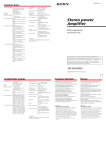
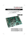
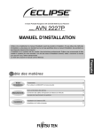
284-0258-00
EA-1232A
Thank you for purchasing this Clarion product.
This power box is used to supply electrical power to
an LCD color monitor or CCD camera.
• Supports automobiles with DC 24V/12V systems.
• Allows connection of 6.5" type LCD color monitor
CJ-981E.
• Supports both color and black-and-white CCD
cameras.
• Supports color CCD camera CC-2000 series (with
zoom function) (Supplied remote control unit can
be used to expand image for easier viewing.)
• The accessory wired remote control can be used
to adjust both zoom and iris.
This equipment has been tested and found to comply with
the limits for a Class B digital device, pursuant to Part 15 of
the FCC Rules. These limits are designed to provide
reasonable protection against harmful interference in a
residential installation. This equipment generates, uses, and
can radiate radio frequency energy and, if not installed and
used in accordance with the instructions, may cause harmful
interference to radio communication. However, there is no
guarantee that interference will not occur in a particular
installation. If this equipment does cause harmful
interference to radio or television reception, which can be
determined by turning the equipment off and on, the user is
encouraged to consult the dealer or an experienced radio/TV
technician for help.
Nous vous remercions de votre achat de ce produit
Clarion.
Ce boîtier d’alimentation est destiné à fournir le
courant électrique à un moniteur couleur à cristaux
liquides ou une caméra CCD.
• Convient à des véhicules à alimentation CC de
24V/12V.
• Permet le branchement d’un moniteur couleur à
cristaux liquides CJ-981E de 6,5 pouces.
• Accepte les caméras CCD couleur ou noir et
blanc.
• Prend en compte les caméras CCD couleur de
série CC-2000 (à fonction zoom). (La
télécommande fournie permet d’élargir l’image
pour en faciliter la vision.)
• La télécommande câblée disponible comme
accessoire permet d’ajuster le zoom et le
diaphragme.
■ BEFORE STARTING / AVANT DE DÉMARRER / VOR INBETRIEBNAHME / PRIMA DI INIZIARE
• BEFORE WIRING, DISCONNECT THE CABLE
FROM THE NEGATIVE BATTERY TERMINAL.
Before doing any electrical wiring, disconnect the
cable from the negative “-” terminal of the
battery. Failure to do so may result in electric
shock or injury due to electrical shorts.
AVERTISSEMENT
• AVANT D’EFFECTUER LES CONNEXIONS,
DÉBRANCHEZ LE CÂBLE DE LA BORNE
NÉGATIVE DE LA BATTERIE.
Avant d’effectuer toute connexion électrique,
débranchez le câble de la borne négative “-” de
la batterie. Le non respect de cet avertissement
peut entraîner un choc électrique ou des
blessures dues à un court-circuit électrique.
WARNUNG
• VOR VERDRAHTUNG DAS KABEL VON DER
NEGATIVEN BATTERIEKLEMME ABTRENNEN.
Vor Ausführung jeglicher elektrischen
Verdrahtungen, das Kabel von der negativen “-”
Klemme der Batterie abtrennen. Wird dies nicht
getan, kann es aufgrund von elektrischen
Kurzschlüssen zu elektrischen Schlägen oder
Verletzungen kommen.
AVVERTENZE
• PRIMA DI PROCEDERE CON I
COLLEGAMENTI, SCOLLEGARE IL CAVO DAL
TERMINALE NEGATIVO DELLA BATTERIA.
Prima di procedere con i collegamenti, scollegare
sempre il cavo dal terminale negativo “-” della
batteria. Non facendolo si possono causare
folgorazioni o infortuni dovuti a corto circuiti.
■ CAUTIONS ON INSTALLATION / PRÉCAUTIONS D’INSTALLATIONS / VORSICHTSMASSNAHMEN FÜR EINBAU / PRECAUZIONI SULL’INSTALLAZIONE
WARNING
• DO NOT USE NUTS OR BOLTS IN THE BRAKE
SYSTEM WHEN MAKING INSTALLATION OR
GROUND CONNECTIONS.
Never use safety-related parts such as bolts or
nuts in the steering or brake systems or tanks to
make wiring installations or ground connections.
Using such parts could disable control of the
vehicle and cause fire etc.
• DO NOT DAMEDE PIPE OR WIRING WHEN
DRILLING HOLES.
When drilling holes in the chassis for installation,
take precautions so as not to contact, damage or
obstruct pipes, tanks or electrical wiring. Failure to
take such precautions may result in fire.
• DO NOT INSTALL IN LOCATIONS WHICH
MIGHT HINDER VEHICLE OPERATION.
Do not install in locations which might create
hazards for the vehicle occupants or hinder
vehicle operation (such as the steering wheel or
gear shift) by obstructing forward vision or
hampering movement etc.
• DO NOT INSTALL THE UNIT NEAR THE
PASSENGER SEAT AIR BAG.
If the unit is not installed correctly the air bag may
not function correctly.
CAUTION
• USE SPECIFIED ACCESSORY PARTS AND
INSTALL THEM SECURELY.
Be sure to use only the specified accessory parts.
Use of other than designated parts may damage
this unit internally or may not securely install the
unit in place as parts that come loose can create
hazards.
Wir danken Ihnen, dass Sie sich für dieses ClarionProdukt entschieden haben.
Dieses Stromversorgungsteil dient zur
Spannungsversorgung eines LCD-Farbmonitors
oder einer CCD-Kamera.
• Für Fahrzeuge mit 24-V- oder 12-V-Batterie geeignet.
• Gestattet den Anschluss des 6,5-Zoll-LCDFarbmonitors CJ-981E.
• Unterstützt sowohl Farb- als auch SchwarzweißCCD-Kameras.
AVERTISSEMENT
• N’UTILISEZ PAS D’ÉCROUS NI DE BOULONS
DANS LE CIRCUIT DE FREINAGE LORS DE
L’INSTALLATION OU DE LA CONNEXION DE
MASSE.
N’utilisez jamais de pièce de sécurité comme des
boulons ou des écrous dans le circuit de direction
ou de freinage ou dans les réservoirs lors de
l’installation des fils ou des connexions de mise à
la masse. Ces pièces pourraient désactiver la
commande du véhicule et provoquer un feu, etc.
• N’ENDOMMAGEZ PAS LES TUYAUX NI LE
CÂBLAGE EN PERÇANT LES ORIFICES.
Quand vous percez les orifices dans le châssis
pour l’installation, veillez à ne pas toucher,
endommager ni obstruer les tuyaux, les réservoirs
ni le câblage électrique. Le non respect de cette
précaution risque de provoquer un feu.
• N’INSTALLEZ PAS DANS UN ENDROIT QUI
RISQUE DE GÊNER LA CONDUITE DU
VÉHICULE.
N’installez pas dans un endroit qui risque de
présenter un danger pour les occupants du
véhicule ou de gêner la conduite du véhicule (par
exemple volant ou embrayage) en obstruant la
vue avant ou en gênant les mouvements, etc.
• N’INSTALLEZ PAS L’APPAREIL PRÈS DE
L’AIRBAG DU SIÈGE DU PASSAGER.
Si l’appareil n’est pas correctement installé,
l’airbag risque de ne pas fonctionner
adéquatement.
ATTENTION
• UTILISEZ LES ACCESSOIRES SPÉCIFIÉS ET
INSTALLEZ-LES SOLIDEMENT.
Veillez à utiliser uniquement les accessoires
spécifiés. L’utilisation d’autres accessoires non
spécifiés risque d’endommager l’intérieur de
l’appareil ou de ne pas maintenir l’appareil
solidement en place car des pièces qui deviennent
lâches risquent de présenter un danger.
WARNUNG
• FÜR DEN EINBAU ODER DIE
ERDUNGSANSCHLÜSSE NIEMALS MUTTERN
ODER SCHRAUBEN DES BREMSSYSTEMS
VERWENDEN.
Für die Kabelverbindungen oder
Erdungsanschlüsse niemals Sicherheitsteile
verwenden, wie z.B. Schrauben oder Muttern der
Steuerung, des Bremssystems oder des
Kraftstofftanks. Durch Verwendung solcher Teile
könnte die Kontrolle über das Fahrzeug verloren
gehen oder ein Feuer entstehen, usw.
• KEINE ROHRLEITUNGEN ODER
VERDRAHTUNGEN BEIM BOHREN VON
LÖCHERN BESCHÄDIGEN.
Beim Bohren von Löchern im Chassis für den
Einbau, darauf achten, daß keine Rohrleitungen,
Kraftstofftanks oder elektrischen Verdrahtungen
berührt, beschädigt oder blockiert werden.Wird dies
nicht beachtet, könnte es zu einem Feuer kommen.
• NICHT AN STELLEN EINBAUEN, DIE DEN
FAHRZEUGBETRIEB BEHINDERN.
Nicht an Stellen einbauen, die Gefahren für die
Fahrzeuginsassen verursachen oder den
Fahrzeugbetrieb behindern (z.B. das Lenkrad
oder Gangschaltung), indem die Sicht oder
Bewegungsfreiheit usw. eingeschränkt wird.
• DIESES GERÄT NICHT IN DER NÄHE DES
AIRBAG DES BEIFAHRERSITZES EINBAUEN.
Bei unsachgemäßem Einbau des Gerätes
funktioniert der Airbag u.U. nicht einwandfrei.
VORSICHT
• NUR DIE ANGEGEBENEN ZUBEHÖRTEILE
VERWENDEN UND DIESE FEST MONTIEREN.
Nur die angegebenen Zubehörteile
verwenden.Werden andere Bauteile als die
angegebenen verwendet, könnte diese Einheit im
Innern beschädigt oder nicht sicher eingebaut
werden, da sich lösende Teile gefährlich sind.
AVVERTENZE
• NEL CORSO DELL’INSTALLAZIONE O DELLA
MESSA A TERRA, NON AGGIUNGERE
BULLONI O DADI NEL SISTEMA DEI FRENI.
Per i collegamenti o la messa a terra, non usare
pezzi legati alla sicurezza, ad esempio bulloni o
dadi nel sistema dello sterzo o dei freni, oppure
nel serbatoio. Facendone uso si può pregiudicare
il controllo del veicolo, causare incendi, ecc.
• NELL’APRIRE FORI CON UN TRAPANO, NON
DANNEGGIARE TUBAZIONI O CAVI.
Nell’aprire fori col trapano nel telaio nel corso
dell’installazione, fare attenzione a non toccare,
danneggiare o ostruire tubazioni, serbatoi o cavi
elettrici. Non rispettando queste precauzioni è
possibile causare incendi.
• NON INSTALLARE IL SISTEMA IN POSIZIONI
CHE POSSANO IMPEDIRE IL
FUNZIONAMENTO NORMALE DEL VEICOLO.
Non installare il sistema in posizioni che possano
mettere in pericolo i passeggeri o impedire la
manovra del veicolo (ad esempio intralciando il
movimento del volante o del cambio), impedendo
la visione o il movimento del conducente.
• NON INSTALLARE QUESTO SISTEMA VICINO
ALL’AIRBAG DEL PASSEGGERO.
Se non venisse installato correttamente, l’airbag
potrebbe non aprirsi.
•
•
•
•
•
•
•
Installation manual .............................................. 1
Wired remote control unit .................................... 1
Mounting brackets ............................................... 2
Rubber spacer ..................................................... 1
Power cord .......................................................... 1
5 x 16 self-tapping screws ................................... 4
M4 x 8 hex bolts with washers ............................. 4
• KEEP ELECTRICAL CABLES TOGETHER TO
AVOID OPERATING HAZARDS.
Arrange wiring and cables in compliance with the
installation manual to prevent obstruction when
driving. Cables or wiring that obstructs or hangs
up on places such as the steering wheel, gear
lever, brake pedals can be extremely hazardous.
• DO NOT CUT AWAY THE WIRE SHEATH AND
USE POWER TO OTHER EQUIPMENT.
Never cut away the cable shielding to use power
to another piece of equipment. Doing so will
exceed the current carrying capacity of the wire
and result in fire or electric shock.
CAUTION
• MAKE THE CORRECT CONNECTIONS.
Failure to make the correct connections can
cause fire or accident to occur.
• ARRANGE THE WIRING SO IT IS NOT
CRIMPED OR PINCHED.
Route the cables and wiring so as not be crimped
by moving parts like seat rail or make contact with
sharp or pointed spots which might damage the
wiring.
+284-0258-00_EFDI
1
Vi ringraziamo per aver acquistato questo prodotto
Clarion.
Questo gruppo di alimentazione viene usato per
alimentare un monitor LCD a colori o una
fotocamera a CCD.
• Supporta vetture con impianto elettrico a corrente
continua, 24 V/12 V.
• Permette il collegamento dei monitor LCD a colori
da 6.5" CJ-981E.
• Supporta fotocamere a CCD sia a colori che in
bianco e nero.
• Supporta le fotocamera a CCD a colori della serie
CC-2000 (con funzione di zoom) (Il telecomando
in dotazione può venire usato per ingrandire
un’immagine e renderla più bene visibile.)
• Il telecomando in dotazione è in grado di
controllare sia lo zoom che il diaframma.
AVERTISSEMENT
• MAINTENEZ LES CÂBLES ÉLECTRIQUES
ENSEMBLE POUR ÉVITER TOUT RISQUE DE
DANGER.
Disposez le câblage et les câbles comme décrit
dans le manuel d’installation pour éviter toute
obstruction pendant la conduite. Les câbles ou les
fils qui obstruent ou qui surplombent des endroits
comme le volant, le levier de changement de
vitesse ou la pédale de frein peuvent être
extrêmement dangereux.
• NE COUPEZ PAS LA GAINE DU FIL POUR
ALIMENTER UN AUTRE APPAREIL.
Ne coupez jamais le blindage du câble pour
alimenter un autre appareil. Vous dépasseriez la
capacité de transport du courant du fil, ce qui
provoquera un feu ou un choc électrique.
ATTENTION
• EFFECTUEZ LES CONNEXIONS
CORRECTEMENT.
Des connexions incorrectes risquent de provoquer
un feu ou un accident.
• DISPOSEZ LES CÂBLES DE FAÇON QU’ILS
NE SOIENT NI COINCÉS NI PINCÉS.
Acheminez les câbles et les fils de façon qu’ils ne
soient pas coincés par des pièces mobiles, par
exemple les rails de siège, et qu’ils n’entrent pas
en contact avec des éléments pointus ou
coupants qui pourraient les endommager.
•
•
•
•
•
•
•
Manuel d’installation ............................................ 1
Télécommande câblée ........................................ 1
Applique de montage .......................................... 2
Entretoise caoutchoutée ...................................... 1
Cordon d’alimentation .......................................... 1
Vis autotaraudeuse 5 x 16 ................................... 4
Boulons hexagonaux M4 x 8 avec rondelle ......... 4
■ Power Box Installation
■ Installation du boîtier
d’alimentation
■ Einbau des
Stromversorgungsteils
■ Installazione del gruppo di
alimentazione
• ELEKTRISCHE KABEL SOLLTEN SICHER
AUSGELEGT WERDEN,UM GEFÄHRDUNG
DES FAHRZEUGBETRIEBS ZU VERMEIDEN.
Die Verdrahtung sowie Auslegung der Kabel
entsprechend der Einbauanleitung ausführen, um
eine Gefährdung des Fahrzeugbetriebs zu
vermeiden. Kabel oder Drähte, die Hindernisse
bilden oder an Stellen wie dem Lenkrad,
Schalthebel oder den Bremspedalen befestigt
sind, können zu gefährlichen Situationen führen.
• NIEMALS DEN KABELMANTEL ENTFERNEN
UND ANDERE GERÄTE MIT STROM
VERSORGEN.
Niemals die Kabelabschirmung entfernen, um
andere Geräte mit Strom zu versorgen. Sonst wird
die Strombelastbarkeit des Kabels überschritten,
was zu einem Feuer oder elektrischen Schlägen
führen kann.
• The installation location for the wired remote
should be one that does not interfere with the
driver’s normal operation of the vehicle; use the
supplied rubber spacer with two-sided adhesive to
fix the remote control in place.
Avoid installing the remote control in locations
exposed to direct sunlight or high temperatures.
• Arrange the remote’s cord in such a way that it
does not interfere with driving, and use cord
clamps or other means to fix in place.
Self-tapping screws
Vis autotaraudeuses
Gewindeschneidschrauben
Viti autofilettanti
(5 x 16)
Mounting bracket
Applique de montage
Befestigungsbügel
Staffa di montaggio
• Pour l’installation de la télécommande câblée,
choisissez un emplacement où elle ne gênera pas
les mouvements normaux du conducteur du
véhicule; utilisez l’entretoise caoutchoutée fournie
à deux faces adhésives pour fixer la
télécommande à l’endroit voulu.
Évitez d’installer la télécommande à un endroit
exposé aux rayons directs du soleil ou à une forte
température.
• Cheminez le cordon de la télécommande de
manière qu’il ne gêne pas la conduite et utilisez
des serre-fils ou des attaches pour immobiliser le
cordon.
6)
(18
(44
Hex bolts with washer
Boulons hexagonaux avec rondelle
Sechskantschrauben mit Unterlegscheiben
Bulloni esagonali con rondella
)
VORSICHT
CAMERA
VIDEO IN
• ANSCHLÜSSE KORREKT AUSFÜHREN.
Werden Anschlüsse nicht korrekt ausgeführt, kann
dies zu einem Feuer oder Unfall führen.
• DARAUF ACHTEN DAS KABEL NICHT
GEQUETSCHT ODER ZUSAMMENGEPRESST
WERDEN.
Die Kabel und Drähte so auslegen, daß sie nicht
durch Bewegung des Sitzes gequetscht werden
sowie scharfe oder spitze Stellen berühren, die
das Kabel beschädigen könnten.
Wired remote control unit
Télécommande câblée
Kabelfernbedienung
Telecomando con filo
DISPLAY
AVVERTENZE
Green / Vert
Grün / Verde
1
Brown / Marron
Braun / Marrone
2
Orange / Orange
Orange / Arancione
3
Black/White / Noir/Blanc
Schwarz/Weiß / Nero/Bianco
Yellow/White / Jaune/Blanc
Gelb/Weiß / Giallo/Bianco
ATTENZIONE
• CONTROLLARE CHE TUTTI I COLLEGAMENTI
SIANO CORRETTI.
Se i collegamenti non sono corretti si possono
avere incendi o incidenti.
• STENDERE TUTTI I FILI IN MODO CHE NON
VENGANO COMPRESSI O PIZZICATI.
Stendere i cavi ed i fasci fili in modo che non
vengano compressi da parti in movimento, ad
esempio le rotaie dei sedili, e che non entrino in
contatto con oggetti taglienti o appuntiti che li
possano danneggiare.
Manuale di installazione ...................................... 1
Telecomando con filo ........................................... 1
Staffa di montaggio .............................................. 2
Distanziatore in gomma ....................................... 1
Cavo di alimentazione ......................................... 1
Viti autofilettanti da 5 x 16 ................................... 4
Bulloni esagonali M4 x 8 con rondella ................. 4
• Die Fernbedienung muss an einer Stelle befestigt
werden, an der sie die normalen Aktionen des
Fahrers beim Lenken des Fahrzeugs nicht
behindert; verwenden Sie das mitgelieferte
Gummidistanzstück mit beidseitig haftendem
Klebestreifen, um die Fernbedienung an der
gewünschten Stelle zu befestigen.
Vermeiden Sie eine Befestigung der Fernbedienung
an einer Stelle, die direkter Sonneneinstrahlung
oder hohen Temperaturen ausgesetzt ist.
• Verlegen Sie das Kabel der Fernbedienung so,
dass es beim Lenken des Fahrzeugs nicht im
Wege ist, und sichern Sie es mit Kabelschellen
o.Ä.
• La posizione di installazione del telecomando con
filo deve essere tale da non interferire con la
guida del veicolo; per fissare il telecomando in
posizione, usare il distanziatore in gomma in
dotazione con nastro adesivo a doppio lato.
Evitare l’installazione del telecomando in posizioni
esposte a luce solare diretta o alte temperature.
• Stendere il cavo del telecomando in modo che
non interferisca con la guida ed usare fascette
fermafili o altri strumenti simili per fermarlo in
posizione.
Peel off the protective
film and fix to vehicle.
Enlevez la pellicule
protectrice et fixez
sur le véhicule.
Die Schutzfolie abziehen
und am Fahrzeug befestigen.
Togliere la pellicola protettiva
e fissare al veicolo.
Peel off protective film and
fix to remote control unit.
Enlevez la pellicule protectrice
et fixez sur la télécommande.
Die Schutzfolie abziehen und
an der Fernbedienung befestigen.
Togliere la pellicola protettiva
e fissare al telecomando.
4. Wring / Câblage / Verdrahtung / Cablaggi
• USARE SOLO GLI ACCESSORI SPECIFICATI
ED INSTALLARLI FERMAMENTE.
Usare solo accessori del tipo specificato.
L’uso di pezzi diversi può causare danni interni a
quest’unità o impedirne l’installazione sicura,
rendendo possibili guasti ed incidenti.
• NON TAGLIARE L’ISOLANTE DEI FILI E NON
USARLI PER ALIMENTARE ACCESSORI.
Non tagliare mai l’isolante dei cavi per alimentare
un accessorio. Facendolo si può superare la
capacità di erogazione del filo e causare incendi o
folgorazioni.
•
•
•
•
•
•
•
(M4 x 8)
ATTENZIONE
• PER EVITARE POSSIBILI INCIDENTI, LEGARE
IN UN FASCIO I VARI CAVI ELETTRICI.
Stendere i fasci fili ed i cavi come specificato nel
manuale in modo che non intralcino la guida. I
cavi ed i fasci fili che ostacolano il movimento del
volante, della leva del cambio e del pedale dei
freni possono essere estremamente pericolosi.
Montageanleitung ................................................ 1
Kabelfernbedienung ............................................ 1
Befestigungsbügel ............................................... 2
Gummidistanzstück ............................................. 1
Spannungsversorgungskabel .............................. 1
Gewindeschneidschrauben 5 x 16 ...................... 4
Sechskantschrauben M4 x 8 mit
Unterlegscheiben ................................................. 4
■ Installing the Wired Remote / Installation de la télécommande câblée
■ Befestigung der Kabelfernbedienung / Installazione del telecomando con filo
VIDEO OUT
WARNUNG
•
•
•
•
•
•
•
3. Installation / Installation / Installation / Installazione
■ CAUTIONS ON WIRING / PRÉCAUTIONS DE CÂBLAGE / VORSICHTSMASSNAHMEN FÜR VERDRAHTUNG / PRECAUZIONI SUI CABLAGGI
WARNING
• Unterstützt Farb-CCD-Kameras der Serie
CC-2000 (mit Zoomfunktion). (Die
mitgelieferte Fernbedienung kann zur
Erweiterung des Bilds für bequemere
Betrachtung verwendet werden.)
• Die mitgelieferte Fernbedienung kann zur
Einstellung sowohl der Zoomfunktion als
auch der Blendenfunktion verwendet
werden.
Installation manual
Manuel d’installation
Montageanleitung
Manuale di installazione
2. Parts Included / Pièces jointes / Mitgeliefertes Zubehör / Componenti in dotazione
1. Safety Precautions / Précautions de Sécurité / Sicherheitshinweise / Precauzioni di sicurezza
WARNING
For DC 12 / 24V vehicles
Pour véhicules à CC 12 / 24 V
Für Fahrzeuge mit 12-V- oder 24-V-Batterie
Per veicoli a c.c., 12 / 24 V
Power Supply Box / Boîtier d’alimentation
Stromversorgungsteil / Gruppo di alimentazione
Red/White / Rouge/Blanc
Rot/Weiß / Rosso/Bianco
4
5
6
7
Black / Noir
Schwarz / Nero
8
1A fuse / Fusible 1A / Sicherung 1 A / Fusibile da 1 A
Red / Rouge / Rot / Rosso
9
Blue / Bleu / Blau / Blu
0
CAMERA: Connect to CCD camera
VIDEO IN: Video input connector (RCA pin jack)
VIDEO OUT: Video output connector (RCA pin jack)
DISPLAY: Connect to LCD monitor CJ-981E
1 Parking brake signal wire; connect to ground wire of
parking brake lamp.
2 Illumination (DIMMER) power wire; connect to
vehicle’s light switch (DC +11 to +32V).
3 Reverse gear signal wire; connect to vehicle’s
reverse gear switch (DC +11 to +32V).
Not Used.
4
* To prevent accidents,
5
cover exposed wire ends
6 12V B/U OUTPUT
with insulating tape.
7 12V ACC OUTPUT
8 Ground (GND)
9 Backup signal power (DC +24V/+12V)
0 ACC power (DC +24/+12V)
CAMERA: An CCD-Kamera
VIDEO IN: Videoeingang (Cinchbuchse)
VIDEO OUT: Videoausgang (Cinchbuchse)
DISPLAY: An LCD-Monitor CJ-981E
1 Feststellbremsen-Signalleitung; verbinden Sie diesen Draht
mit dem Massedraht der Feststellbremsen-Kontrollleuchte.
2 Dimmerschalterdraht (DIMMER); verbinden Sie diesen Draht
mit dem Beleuchtungsschalter des Fahrzeugs (DC 11–32 V).
3 Rückwärtsgang-Signaldraht; verbinden Sie diesen Draht mit
dem Rückwärtsgangsschalter des Fahrzeugs (DC 11–32 V).
4
Nicht verwendet.
5
* Umwickeln Sie mit die blanken
6 12V B/U OUTPUT
Drahtenden mit Isolierband, um
7 12V ACC OUTPUT
Unfälle zu verhindern.
8 Masse (GND)
9 Reservesignal-Spannungsversorgung (DC 24/12 V)
0 ACC-Spannungsversorgung (DC 24/12 V)
CAMERA : Branchez sur la caméra CCD
VIDEO IN : Connecteur d’entrée vidéo (Prise à broches
RCA)
VIDEO OUT : Connecteur de sortie vidéo (Prise à
broches RCA)
DISPLAY : Branchez sur le moniteur à cristaux liquides
CJ-981E
1 Fil de signal de frein à main : raccordez au fil de
masse du voyant du frein de stationnement.
2 Fil d’alimentation d’éclairage (DIMMER) : raccordez
au commutateur général d’éclairage (CC +11V à
+32V) du véhicule.
3 Fil de signal de marche arrière : raccordez au
commutateur de marche arrière (CC +11V à +32V)
du véhicule.
4
Non utilisé.
5
* Pour éviter tout accident,
6 SORTIE 12V B/U
recouvrez les bouts
7 SORTIE 12V ACC
exposés des fils au
moyen d’un morceau de
ruban isolant.
8 Masse (GND)
9 Alimentation signal de secours (CC +24V/+12V)
0 Alimentation ACC (CC +24V/+12V)
CAMERA: Collegamento di una fotocamera a CCD
VIDEO IN: Connettore di ingresso video (con spinotti a spillo
RCA)
VIDEO OUT: Connettore di uscita video (con spinotti a spillo
RCA)
DISPLAY: Da collegare al monitor LCD CJ-981E
1 Filo del segnale del freno di parcheggio; da collegare al filo
di messa a terra della luce del freno di parcheggio.
2 Filo di alimentazione luci (DIMMER); da collegare
all’interruttore delle luci del veicolo (c.c. da +11 V a +32 V).
3 Filo della retromarcia; da collegare all’interruttore della
retromarcia del veicolo (c.c. da +11 V a +32 V).
4
Non usato
5
* Per evitare incidenti, coprire le
6 USCITA B/U A 12 V
estremità denudate dei fili con
7 USCITA ACC A 12 V
nastro isolante.
8 Messa a terra (GND)
9 Alimentazione di emergenza (c.c. da +24 V/+12 V)
0 Alimentazione ACC (c.c. da +24 V/+12 V)
Clarion Co., Ltd.
Printed in Japan 2005/5 (C/A.K)
5A fuse / Fusible 5A
Sicherung 5 A /
Fusibile da 5 A
05.4.27, 17:59
EA-1232A
284-0258-00