1
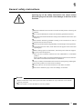
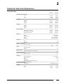
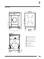
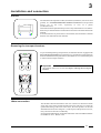
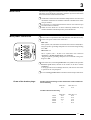
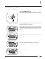
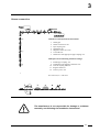
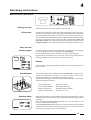
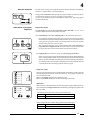
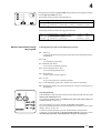
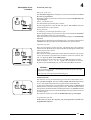
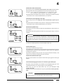
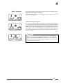
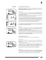
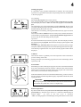
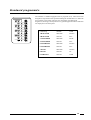
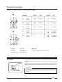
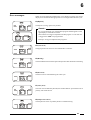
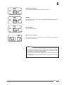
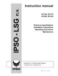
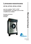
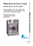
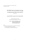
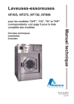
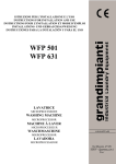
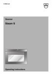
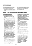
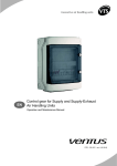
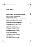
Part No. D0051
Contents
1 General safety instructions .............................................................. 3
2 Technical data and dimensions ....................................................... 4
Technical data ................................................................................ 4
Dimensions ..................................................................................... 5
3 Installation and connection ............................................................. 6
Ground ............................................................................................ 6
Removing the transport brackets .................................................... 6
Water connection ............................................................................ 6
Water drain ..................................................................................... 7
Main power connection .................................................................... 7
Liquid soap connection ................................................................... 8
Steam connection ........................................................................... 9
4 Operating instructions ..................................................................... 10
Machine with start button ................................................................ 10
5 Standard programs .......................................................................... 18
6 Technical remarks ............................................................................ 19
Internal connection of the electrical heating .................................... 19
Tilt switch ....................................................................................... 19
Error messages .............................................................................. 20
7 Maintenance of the machine ........................................................... 22
Code: 249/00173/00
19-12-00
Contents
1
General safety instructions
Ignoring any of the safety instructions can cause serious
personal injury and can also cause damage to the linen or the
machine
S Read the installation and instruction manual carefully before connecting the
machine.
S It is recommended that the machine be installed by qualified technicians.
S The machine should be installed according to the installation instructions. (See
chapter 3)
S The machine should be grounded according to the instructions in order to
eliminate the risk of electrocution.
S Do not expose the machine to high humidity or extreme high or low temperatures.
S Cut off all main water inlets, steam and electrical supplies at the end of each
operating day.
S Before starting repairs or maintenance, shut off all power and water supplies.
S To prevent fire and explosion:
Keep the area around the machine free from inflammable or combustible
products.
Do not put fabrics that are treated with inflammable products into the machine.
These fabrics should be hand-washed or air-dried first.
S Always carefully read and follow the instructions on the packing of detergents.
Store these products out of the reach of children.
S Always take into account the instructions on the labels of clothes.
S Never allow children to play in the surroundings of a machine.
Remark:
S These instructions surely cannot prevent all risks of accidents. It is up to the user to act with the
utmost precaution.
S Do not hesitate to contact the dealer in case of a problem.
3
2
Technical data and dimensions
Technical data
HF 176
HF 234
16,0 kg
17,6 kg
19,5 kg
21,3 kg
23,4 kg
26,0 kg
750 mm
399 mm
176 Lit.
750 mm
530 mm
234 Lit.
1505 mm
900 mm
885 mm
1505 mm
900 mm
985 mm
395 mm
630 mm
820 mm
395 mm
630 mm
820 mm
Capacity (dry weight)
1/11
1/10
1/9
Cylinder
Diameter
Depth
Volume
Cabinet
Height
Width
Depth
Front loading
Diameter door opening
Door height - lower edge
Door height - center
Speed
Wash
Distribution
Spin
High spin
10...50 tr/min.
100 tr/min.
250...500 tr/min.
500...1000 tr/min.
G-force
Spin
High spin
74
373
Motors (3-phase)
4p. 1470 rot./min
2 kW
3 kW
Drain
Depend-O-Drain
Option
3"
2"
Water-inlet
Hard, soft, hot water & cool-down
3/4"
Steam connection
Steam connection
3/8"
Heating
Electric 220/380 V
Electric 380 V
Steam
Boiler fed
Boiler fed (with auxiliary heating)
12/15/18 kW
24 kW
X
X
X
Packing dimensions
(H x W x D)
1650x1020x1150 mm
Weight
Net
Gross
455 kg
524 kg
570 kg
630 kg
4
2
Dimensions
SA. Hard water connection 3/4"
SB. Warm water connection 3/4"
SC. Soft water connection 3/4"
SD. Electrical connection
SE. Electrical connection clamps
SF. Output steam valve
SG. Water drain
SH. Steam connection
S I. Ventilation soap dispenser
5
3
Installation and connection
Ground
The machine must be placed on a flat, solid surface (metal base, concrete or solid
ground). It is recommended that the machine be anchored on the provided
places (A) in the base, especially in case of a plinth
(see Dimensions 2).
The machine must be placed entirely level. For easy maintenance it is recommended to keep a minimal distance of 600 mm between the wall and the back of the
machine.
If several machines are placed next to each another, there should be a minimal
distance of 30 mm between each machine.
Removing the transport brackets
To prevent damage during transportation, the machine has been equipped with
four red transport brackets (D) to eliminate every possible movement of the tub.
After the machine has been placed level, take off the service- and the back panel
to remove these transport brackets.
Important
The machine must never be activated before removing these transport
brackets.
Water connection
The machine is delivered with hoses with 3/4" connections. These hoses fit the
water inlet valves of the machine and the main water inlet taps. To ensure the
optimal functioning of the water inlet valves, the water pressure on the inlet
should be between 0,5 and 10 kg/cm² (7 and 145 psi). If the pressure is too low,
the cycle time will increase considerably.
In case of boiler fed machines, a minimum of hot water of 90°C should be available:
For the HF176: 125 l. HF234: 150l.
6
3
Water drain
The machine is equipped with a drain valve with 3" outer diameter (80 mm).
This drain valve should be connected to the drain by means of the drain
elbow which is delivered with the machine.
S The diameter of the main drain should be adapted to the water flow and
S
S
Main power connection
the number of machines. It should be sufficient to handle at least 160L/
min. per machine.
It is necessary to connect the main drain at least on one side to an open
air-brake to allow ventilation.
When the main drain has not been sufficiently deodorized, every
machine should be installed seperately with a deodorizer.
S Remove the cover plate at the back of the machine. (See dimensions (E)).
S Connect the power cable to the connectors.
220V 3AC
220V 3 phase (3AC) should be connected to the connectors “L1,L2,L3”.
The green/yellow grounding clamp has to be connected to the grounding
wire “PE”.
380 V 3AC + N
380 V 3 phase (3AC + N) has to be connected to the connectors
“L1,L2,L3”, the blue neutral to the “N” connector.
The green/yellow grounding clamp has to be connected to the grounding wire “PE”.
S After connection, check the spin direction. The cylinder must spin in the
direction of the arrow, showed on the sticker on the door window
(clockwise).
A wrong spin direction can damage the motor, and can also cause water
to spurt from the soap dispenser.
S In case of wrong spin direction: switch the terminal clamps of the motor
Power of the breaker plugs:
machine with steam heating or boiler fed machines without additional
electrical heating
220V 3AC
16 A
380V 3AC + N
16 A
machine with electrical heating
12 kW
15 kW
18 kW
21 kW
24 kW
220V 3AC
40 A
50 A
50 A
-------
380V 3AC + N
20 A
25 A
32 A
40 A
40 A
7
3
Liquid soap connection (option)
Connection of the liquid soap
hoses
A rubber connection has been placed over the air break opening at the back
of the machine. There are 5 holes in this rubber connection, through each
of which a liquid soap hose can be driven (S1...S5). Press the hoses until they
appear well inside the soap dispenser.
The central gap in the rubber connection remains and serves as air breaker.
Electrical connection of
the liquid soap pumps
On machines equipped with a liquid soap connection, connect the wires
directly on the print board next to the ground wire connection (option).
Connect as indicated on the wiring diagram.
The two connectors on the right give a tension of 220V ~ (max. 4A) which
can be applied to drive 220V ~ soap pumps. If more than 4A is required, an
external tension will have to be used. 6 connections have been provided,
of which one (S6) can be used to drive a waterproofing pump (e.g. for rain
coats, etc.).
The 220V can be transformed to other values to drive other type soap
pumps.
Example: pumps 24V ~.
Also, pumps with different operating tension can be combined.
Example: 5 pumps 220V ~ and 1 pump 24V ~.
With an external tension 24V DC
8
3
Steam connection
With direct steam injection into the machine
1.
2.
3.
4.
5.
6.
7.
Steam pipe
Steam cut-off valve 3/8"
Pipe coupling 3/8"
Steam filter 3/8"
Magnetic steam valve 3/8"
Curve MF 3/8"
Steam hose with appropriate pipe coupling 3/8"
Added parts for steam heating with heat exchanger
3.
9.
10.
11.
12.
Double pipe coupling 1/2"
Condensation accumulator with filter 1/2"
Conical coupling MM 1/2"
Single window 1/2"
One-way valve 1/2"
M = inner wire, F = outer wire
The manufacturer is not responsible for damage or accidents
caused by not following the installation instructions!
9
4
Operating instructions
Machine with start button
Opening the door
Fill the drum
Push the red button on the door handle to open the door.
Sort the linen according to the type and required temperature of the linen. Empty
all pockets of the garments so that no garments can be damaged and no left articles
can cause damage to the machine. Turn sleeves of shirts, blouses inside out. It is
recommended to mix small and large items to enhance the drop of the linen during
the wash cycle and hence improve the wash quality. Wash loads of below 80%
of machine capacity can obstruct the proper functioning of the machine and can
damage the machine. Overloading the machine can also lead to a bad wash result.
Close the door
Select program
On machines with a start button, the programmer can contain up to 100 programs
(0-99). The program number is displayed on the right display.
By pressing the SELECT-button (P), the next program will be displayed.
By pressing the ECO-button (E), the previous program will be displayed. By
keeping this button pressed, this function will be accelerated.
Remark
Select program “0” by keeping the SELECT-button pressed continuously for more
than 5 seconds.
Add detergent
It is recommended to only use detergents with a “foam-breaker”. These are often
found in the launderette or laundry or can easily be found in retail stores.
Recommended doses are mentioned on the detergent packing.
Overdosing of detergents can lead to reduced wash results and “overfoaming”
which can damage the machine.
Left compartment A:
Central compartment B:
Right compartment C:
Bottom compartment D:
Economy Wash
Prewash (1st wash)
Main Wash (2nd wash)
Final Rinse (fabric softener)
Direct access to tub
Moderately soiled linen can be washed using the Economy Wash function, which
reduces the water level of washes and rinses by 20%, allowing savings of water
and energy.
Press the ECO-button during the wash cycle to activate the economy wash
function. The ECO-LED will light up.
At the end of the program the ECO-function will be automatically eliminated. If
the ECO-function is required in the following wash cycle as well, reactivate this
function by repeating the actions described above.
10
4
Start the machine
Start the wash-cycle by pressing the Start button (S) and releasing it immediately.
The door is sealed and the cycle-LED lights up.
During the first 2 minutes after starting, the program number is blinking and you
can change the program in case of a possibly wrong selection.
To do so, select another program with the SELECT button (P). This new program
will start immediately.
Indications of program
sequence
Display information
The left display will indicate the temperature of the wash bath - in °C or °F (on
machines where this function has been selected).
The central display shows the remaining time to the end of the wash cycle.
For programs which are being run for the first time, the machine will take a
theoretical time estimate. If this time indication does not correspond to the real
cycle time, the cycle time will be corrected from the second cycle onwards
(Self-Teaching function of the machine).
This correction will have to be preprogrammed and is not activated on
program numbers higher than 20. The corrected time will also be lost when
the power has been cut from the machine for more than 24 hours.
The right display will continue to show the selected program number.
If a Level-stop was programmed (which halts the programmer during the filling
of the cylinder) and/or a Heat-stop (which stops the programmer during the
heating up of the wash bath, then the respective LED’s light up in the display.
Once the required water level and/or temperature have been reached, the LED
is turned off and the internal programmer advances again.
Wash cycle-LED’s
Each program segment has a corresponding LED. Each of these 6 LED’s light up
when the appropriate segment is executed. This way, the program sequence can
be accurately followed.
When a LED blinks, the machine is taking up water.
When a LED blinks slowly, the machine is heating up the water.
Spin-LED’s
When the water is drained at the at the end of a program segment and the machine
spins if so desired, the left spin-LED (intermediate spin) will light up together with
the cycle-LED.
- Functioning of the spin-LED’s during intermediate spin:
LED
Interm. spin
drain/distribution
blinking rapidly
low spin
continuously
coast
continuously
- Functioning of the spin-LED’s during gentle-intermediate spin:
LED
Interm. spin
drain/distribution
blinking rapidly
low spin
blinking slowly
coast
blinking slowly
11
4
During final spin, both the left spin-LED (intermediate spin) will light up together
with the right spin-LED (final spin).
- Functioning of the spin-LED’s during final spin:
LED
drain/distribution
Interm. spin
blinking rapidly continuously
Final spin
continuously
low spin
continuously
high spin
coast
tumble
slowly
continuously
off
slowly
continuously
rapidly
coast
tumble
- Functioning of the spin-LED’s during gentle-final spin:
LED
Interm. spin
Final spin
Manual interventions during
the program
drain/distribution
low spin
high spin
blinking rapidly
slowly
----
slowly
off
continuously
continuously
----
continuously
rapidly
Following functions can be activated during the program:
F1 = Time stop
To increase the duration of a program segment beyond its originally programmed duration.
F2 = Soak
To soak heavily soiled linen
F3 = Reduced wash action
To avoid wear of delicate garments
F4 = Execute high spin as low spin
To avoid creasing delicate linen
F5 = Rapid advance
To skip certain program segments
F6 = No spin
To give total protection to delicate garments
F7 = on the left display appears the number of revolutions of the drum.
F8 = changing the number of revolutions at final spin. In order to limit the rpm for
delicate linen.
Selecting a function
Push the SELECT-button (P) at the time the special function needs to be activated
and keep the button depressed.
Now push the START-button (S) simultaneously and release same. Only now
release the SELECT-button (P).
The central display now shows F1 and this function is now active.
By pressing the SELECT-button (P) the next function will appear on the central
display. And so on up to F8.
To return to normal operation, press the START-button (S) and release.
A function is also terminated by selecting another function. Functions are also
automatically ended and switched off at the end of the each program.
12
Description of the
functions
4
Function F1 (Time stop)
During the wash cycle:
The wash time is stopped. The temperature, water level and wash action remain
the same as programmed.
During the wash cycle, this function remains active until the START button (S)
is pressed again.
During intermediate spin :
The intermediate spin normally lasts 1 minute.
By activating function F1, the machine will spin for nine minutes unless the
START button (S) is pressed earlier.
During final spin :
At final spin, you have high spin after low spin.
By activating F1 during low spin, this low spin will be extended to15 minutes
unless the START button (S) is pressed earlier.
If the 15 minutes of low spin have been completed, the high spin is automatically
canceled.
By activating F1 after the preprogrammed low spin, you will have a maximum of
14 minutes of high spin unless the START button (S) is pressed earlier.
Adjustable stop time :
Here you can program a certain stop time. The display shows the countdown
of this extra time. When this time is expired, the function will appear automatically
and the program will continue.
Select F1 (see above).
The stop time can be programmed by means of the ECO button (E). By pressing
it once, the stop time is programmed for 10 minutes. From now onwards, “F1”
and “10” appear by turns on the middle display.
By pressing the ECO button (E) once more, you add each time 10 minutes.
After 50 minutes, 1.0, 1.1, 1.2, etc... appear with a maximum of 4.0 hours.
By means of the START button (S), you can each time reduce 10 minutes.
Remark :
The programmed stop time is executed after the decimal point in the right
display has extinguished.
The stop time cannot be programmed during spin.
Function F2 (soak)
This function can only be chosen during prewash, main wash and first rinse.
The cycle time is stopped. The bath is filled till high water level and heated up
to 40 °C (if a higher temperature was programmed, this will be followed).
As long as this temperature is not reached, the machine makes a reduced wash
action ( shorter action time and longer pause time). When the bath has reached
its temperature, the drum will make one left/right rotation every 4 minutes. Should
the temperature fall, the water will be heated again, during which the action will
be reduced again.
This function remains active until the START button (S) is pressed again.
Programmable soak time :
In the same way as for the stop time, you can program the soak time (see
programmable stop time).
13
4
Function F3 (reduced wash action):
By selecting F3, the wash action time and pause time will be reversed; unless
the wash action time was programmed to be shorter than the pause time.
Example: 12 sec. action/3 sec. pause becomes: 3 sec. action/12 sec. pause
6 sec. action/9 sec. pause remains: 6 sec. action/9 sec. pause
This function does not influence the cycle time - the program continues normally
- and remains active until the START-button (S) is pressed.
Function F4 (execute high spin as low spin):
By activating this function, high spin will be automatically replaced by low
spin.
This function does not influence the cycle time - the program continues normally
- and remains active until the START-button (S) is pressed.
Function F5 (rapid advance):
This function is mostly used by technicians and maintenance staff. It allows to
the program.
By pressing and releasing the ECO-button (E), the programs skips to the next
segment.
Attention!
If F5 is activated during final spin, this segment of the program will be skipped
as described above. It is however followed by a coast and tumble time to
disentangle the linen. This special function prevents the user from opening
the machine while the drum is still rotating and represents an important safety
feature.
To return to normal operation, press the START-button (S).
Function F6 (no spin):
This function eliminates all spin action.
Intermediate spin is replaced by a regular wash action. During final spin, only the
programmed low spin time will be completed as regular wash action. High spin
is skipped in its entirety.
This function influences the cycle time - the program continues normally - and
remains active until the START-button (S) is pressed.
Function F7 (indication of the rpm)
By using F7 the number of revolutions of the drum (rpm) appears on the right
display.
Function F8 ( changing the number of revolutions (rpm) at final spin)
By means of F8, the number of revolutions can be changed at high spin. The
programmed number of revolutions appears on the left display.
Each time you press the ECO button (E), the spin decreases with
25 rpm ( min.500).
Each time you press the START button (S), the spin increases with 25 rpm (max.
999).
Remark :
This function has to be selected before final spin has started.
14
4
End of a program
At the end of a program, while the door is being released, the left display shows
End; and the Start-LED is switched off.
After that only the right display will continue to show the program number. This
is the end of the program.
Premature ending of the program
By pressing the START-button (S) during the program, the Start-LED is
switched off and the water is drained from the machine. As long as the water has
not reached the safety level, the door will remain sealed and the display will show
“SLE” (Safety Level) on the left display. Afterwards the display will temporarily
show “End” on the same display and the Start-LED will be switched off. After
that only the right display will continue to show the program number. This is the
end of the program.
Remark:
If any attempt is made to interrupt the program prematurely during a spin
phase of the program, all functions on the display will be temperary
replaced by blinking horizontal dashes. After that only the right display
will continue to show the program number and the door will be released.
This is the end of the program.
15
4
Remarks:
Freely programmable stop-function
Before starting a program it is possible to preprogram a time stop in every
program segment. This function permits special additional functions like adding
bleach or extra detergent to the wash bath.
Programming:
After selecting the program, press the ECO-button (E) and keep it depressed.
Now push the START-button (S) simultaneously and release same. Only now
release the ECO-button (E).
The left display now shows “StO” (Stop) and the right display shows the program
number. The first program sequence LED is switched on.
Confirm by pressing the START-button (S) if a time stop is required in this phase
of the program. If no time stop is needed, press the ECO-button (E) to move on
to the next segment of the program. Run through the entire program in this way.
If needed, return to previous segments by pressing the SELECT-button (P).
Errors can be corrected by returning to the erroneously programmed time stop
in the segment and correcting by pressing the START-button (S).
After the final program segment all programmed time stops will be displayed and
the left display will show “End”. Confirm this program by pressing the STARTbutton (S) again. Now start the program.
Operation:
When a stop is reached during the run of the program, the time will be stopped.
The wash bath will be filled to the appropriate level and temperature and the
programmed wash action is executed.
The left display will alternately show temperature and “StO”, while the central
display is showing “F1”. Now, if so desired, additional detergents can be added.
When this has been done, press the START-button (S) to continue the run of
the program. To remove any possible remains of corrosive products in the tub,
the machine will rinse an additional 2 seconds.
Programmable automatic start
By using this function a program can be started up to 99 hours later.
Programming:
After selecting the program, press the SELECT-button (P) again and keep it
depressed.
Now push the START-button (S) simultaneously and release same. Only now
release the SELECT-button (P).
The left display now shows “DEL” (Delay). The central display shows “10”
(minutes). Every push on the SELECT-button (P) will add 10 minutes to the
delayed start time. Hours and minutes are separated by a decimal point: 1.5 stands
for 1 hour and 50 minutes. After 10, the counting is done by hours.
By pressing the ECO-button (E), the delay time can be counted down.
Operation:
After having set the desired delay time, the count-down can be started by
pressing the START-button (S). During the count-down the displays blink and
the remaining time is counted down. In the last hour the displays blink faster.
When the delay time has elapsed, the program is started automatically.
16
4
Linking 2 programs
It is possible to run 2 programs automatically in sequence. This can be handy
to perform very special functions (like waterproofing outerwear) and add these
to the wash program.
Programming:
First select the program which will be run last.
Now, press the START-button (S) and keep it depressed for at least 5 seconds.
The left display now shows “Add”. Now select the program which will be run
first.
The right display now shows both linked programs alternately: the first to be
run program during the longer time span alternating with the following program
displayed during the shorter time span.
This function is canceled by pressing the START-button (S) again for at least
5 seconds.
This function can be combined with an economy wash, with the functions F1
to F6 and with a programmed start. The freely programmable stop-function can
however only be executed during the first program.
Operation:
Press the START-button (S) to start the programs. The central display will show
the remaining time per program. The total time of both programs together is not
displayed.
The right display alternately shows the program in operation (during a longer
time span) and the second program to be executed (during the shorter time span).
After the first program has been run, only the second program number will be
displayed.
Cool down
This function allows to gradually lower the temperature of the wash bath to
prevent creasing of the linen.
During a cool down, the remaining program time on the central display will be
replaced by “cd”.
Power Failure
Should the power fall out during the program, the water will be drained and the
door can be opened after maximum 3 minutes. When the door remains locked,
and the power comes back up within 24 hours, the program will continue from
there, where it was at the time of the power failure.
If due to breakdown, the door is not unlocked automatically, you have to remove
the service panel (A) below and pull the ring (B), suspended on the left side, while
opening the door.
B
A
Important:
Before opening the door, check that all the water has been drained from the
tub and that the cylinder has come to a complete stop.
Remote stop function
By means of this function, no cycles can be selected anymore during a certain
period of time (e.g. between 10 p.m. and 7 a.m.). This time is determined by an
extern timer.
As soon as the last cycle is finished,
“ OFF “ (blinking) appears on the left display as long as this function is activated.
17
Standaard programma's
The machine is standard equipped with 10 programs (0+9). These have been
designed in cooperation with specialized detergent manufacturers to obtain the
best possible wash results using the most frequently used detergents.
Program 0 (starching) is mostly used in very special applications and is therefore
not displayed on the front panel.
0. Starching
1 RINSE
COLD
1. HOT WASH
2 BATHS
40°/90°C
2. HOT WASH
1 BATH
90°C
3. COLOUREDS
2 BATHS
40°/60°
4. COLOUREDS
1 BATH
60°C
5. SYNTHETICS
2 BATHS
40°/40°C
6. SYNTHETICS
1 BATH
40°C
7. WOOL
2 BATHS
30°/30°C
8. WOOL
1 BATH
30°
9. CURTAINS
1 BATH
COLD
18
Technical remarks
Internal connections of the electrical heating
V
Heating
+
B = Black
Gy = Grey
R = Red
PU = Purple
Y/Gr = Yellow/green
Window
R5
3x380V
R5
12kw
3x2kw
3x2kw
V
LC1D253
+
LC1D0901
15kw
3x2kw
3x3kw
V
LC1D253
+
LC1D1810
18kw
3x3kw
3x3kw
V
LC1D323
+
LC1D1810
21kw
3x3kw
3x4kw
-----------
-----------
+
V
LC1D1810
LC1D1810
24kw
3x4kw
3x4kw
-----------
-----------
V
V
LC1D1810
LC1D1810
Br = Brown
Bu = Blue
W = White
W/B = White/black
W/R = White/red
Tilt switch
3x220V
Remark:
Other executions are available as options.
The tilt switch is mounted on the solid part of the machine. There is a window
around the probe of the tilt switch that is mounted on the movable part of the
machine.
When the machine goes out of balance by overloading or uneven distribution of
the linen, the tilt switch will interrupt this action to prevent damage to the machine.
Important
Probe
To guarantee good functioning, the probe should be centered horizontally
and vertically at 1/3 from the bottom of the tilt window (when machine drum
is empty).
19
6
Error messages
When one of the following malfunctions occurs during a program, the central
display will communicate the appropriate error message at the end of the cycle.
E3 (Eprom)
The Eprom is wrong, replace it by another.
Remark :
For coin op machines, it is possible that a program number appears on the
right display in combination with E3.
This indicates a wrong price adjustment for this program. A coin value “0”
or bigger than “1000” was programmed.
Example : wrong price adjustment for program 5.
E4 (water level)
The appropriate water level was not reached after 15 minutes.
E5 (Heating)
The wash bath did not reach the required temperature after 80 minutes of heating.
E6 (door lock)
The door lock was released during the wash cycle.
E7 (safety level)
The water was insufficiently drained, the machine did not spin and the water is
possibly still inside the tub.
E8 (temperature sensor)
The temperature sensor is probably broken or malfunctioning.
20
6
E9 (motor protection)
The thermo-magnetic protection was activated 5 times.
EA (tilt)
The tilt switch was activated 15 times during final spin and the final spin was
therefore skipped.
Eb (tilt switch)
The tilt switch is blocked.
Mot 2 ( rotation sensor)
The speed detection is not operating properly. The speed meter is probably out
of order or disconnected.
Remark
When a malfunction occurs during a program, the central display will
communicate the appropriate error message at the end of the cycle. When
this malfunction has been removed and a new program has been
selected, this error message also disappears.
When malfunctions E6, E7, E9 or Eb are detected at the start of the wash
cycle, the program will not be started and the error message will remain
on the display.
21
7
Maintenance of the machine
General maintenance
Periodical maintenance
Repair and after-sales
service
S
Clean the entire cabinet of the machine regularly and remove all traces of soap,
etc....
S
Remove all detergent residue in the soap dispenser with hot water.
S
S
Clean the door gasket and remove all detergents and other products.
S
It is recommended to leave the door and the soap dispenser open after use, to
ventilate the machine.
S
The V-belts of the motors should be retightened after two to three months when
first used. This is necessary because these belts are subject to a one-time
stretching when first used. By ignoring this instruction, the belt starts to slip
after a few months and will brake shortly afterwards.
S
S
Check regularly if the filters of the water inlet are not blocked by calcification.
S
An obstructed drain can cause frequent interruption of spinning for safety
reasons.
S
The automatic lubricator needs to be replaced each year. (Order number: 212/
00002/00)
S
In case of important malfunctions and deficiencies which you cannot resolve
yourself, do not hesitate to contact the technical service of your distributor.
Shut off the main water, steam and power connections at the end of each day.
Do not change the setting of the water inlet taps on boiler fed machines once
these have been installed.
If a machine frequently skips the final spin, check whether the probe of the out
of balance switch is still in the appropriate position, that is horizontally
centered and vertically 1/3 from the bottom inside the window. (When the drum
is empty).
Data distributor: Name: ...................................................................................
Address: ...............................................................................
Tel.: ......................................................................................
Data machine: Type: .....................................................................................
Program: ...............................................................................
Date of installation: ...............................................................
Installed by: ..........................................................................
Serial number: .......................................................................
Operation voltage and frequency: ..........................................
The manufacturer reserves the right to change the content of this instruction manual, at all times and without previous notice.
22