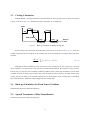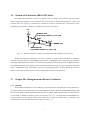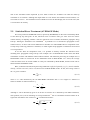
1
Draft report for JAEA-Data/Code (to be submitted in 2007)
Last update 28. Jan. 2005
MVP-BURN: Burn-up Calculation Code Using
A Continuous-energy Monte Carlo Code MVP
(tentative title)
Keisuke OKUMURA, Yasunobu NAGAYA, Takamasa MORI
Japan Atomic Energy Agency (JAEA)
Tokai-mura, Naka-gun, Ibaraki-ken, 319-1195, Japan
E-mail : [email protected]
[email protected]
[email protected]
Note :
Input instructions for the functions below are not described in this draft report.
1) Burn-up calculation for fixed source problems.
2) Flux normalization to the tally parameter defined by user
i
1. Introduction
The continuous-energy Monte Carlo method is the most reliable method in the field of neutron
transport problems because of its precise geometrical modeling and continuous-energy treatment. Recent
progress of fast computers has made it possible to apply the method to burn-up problems. In spite of still
expensive computation costs, the Monte Carlo method is very useful in solving special burn-up problems
for which we have few calculation experiences or difficult problems to treat with conventional
deterministic neutron transport codes. The MVP-BURN code enables the burn-up calculations using a
continuous-energy Monte Carlo code MVP1, 2) and an auxiliary code BURN which calculates the buildup
and decay of nuclides in irradiated materials (hereafter called depletion calculation in distinction from the
burn-up calculation including neutron transport calculation).
An execution of MVP is possible if geometry and material compositions are given. As a result of the
MVP execution, microscopic reaction rates of every nuclide are calculated. On the other hand, depletion
calculation is possible if the microscopic reaction rates are given. Therefore, the coupling of MVP and
BURN can be directly realized only by implementing an interface program between them. The BURN code
has the functions of depletion calculation, file management and interface with MVP. Alternate executions
of MVP and BURN constitute a whole burn-up calculation. In MVP-BURN, an executable of MVP (as an
independent code) is called from BURN.
The prototype of MVP-BURN3, 4) was developed in the latter half of 1990s and it has been widely
used in Japan. To meet users’ requests, continuous improvements of MVP-BURN and its validations4-6)
have been carried out until now. Together with recent revisions2) of MVP and extension of available MVP
libraries7) based on various nuclear data files, the present version of MVP-BURN became a powerful tool
for many burn-up problems. The latest MVP-BURN has the following capabilities which may be difficult
to be treated by conventional deterministic codes.
• Burn-up calculations for eigenvalue problems and fixed source problems. The former is a
conventional way of usual burn-up calculations. The latter can be applied to, for example, burn-up
analyses of non-fissionable material in the irradiation capsule by giving surface source.
• Flexible normalization of flux to the tally parameter defined by user (e.g. fast neutron flux of a
specified monitoring region), as well as usual normalization to a total thermal power or intensity of
fixed sources.
• Cooling calculations at zero power condition between burn-up periods or after burn-up. This
function is indispensable to analyses of post irradiation examinations.
• Burn-up calculations for non-fissionable but burnable materials (e.g. non-fissionable burnable
poison or absorber materials in cluster or cruciform control rods in PWR or BWR).
• Burn-up or parametric survey calculations with changes of geometry size, material composition and
temperature. This allows, for example, changes of control rod position, void fraction, soluble boron
concentration, thermal expansion, along burn-up.
1
• Reactivity calculations along burn-up (so-called branch-off calculations using fuel composition
obtained by usual burn-up calculations)
• Burn-up calculations for the system with randomly distributed many fuel particles using the
statistical geometry model8, 9) of MVP (e.g. coated fuel particles of HTGRs, plutonium spots10) in
MOX fuel pellet, etc.)
In this report, descriptions are given at first on methods of MVP-BURN. Successively, descriptions
are given on available burn-up chain models, an outline of execution procedure, instructions to users about
input data requirements, and information about sample input data equipped in the MVP-BURN files.
2
2. Calculation Scheme
2.1
Depletion Calculation
In this section, we describe a basic calculation scheme of MVP-BURN by assuming a typical
burn-up calculation, where an eigenvalue calculation is done with MVP and neutron flux levels are
normalized to a total thermal power of the system under consideration, although these conditions are not
restrictions for MVP-BURN.
As shown in Fig. 2.1.1, MVP-BURN employs two kinds of time subtractions since the
continuous-energy Monte Carlo method is time-consuming. One is a “burn-up step” with a relatively long
time span, and the MVP calculation is carried out at the start point of each burn-up step. Each burn-up step
is divided into many sub-steps for the depletion calculation by BURN. The sub-step is the other one.
Power
Pn+1
initial fuel composition
for n-th step
MVP
Pn
m-th sub-step period
MVP
n-th burn-up step period
tn
tm tm+1
Fig. 2.1.1
tn+1
Burn-up time
Burn-up step and sub-step in MVP-BURN
To avoid confusions, we call the time span as “step” or “step period”, while we call the two sides of
a step period as “step start point” and “step end point”, which are specified in Fig. 2.1.1 by a filled circle
and an inverted triangle, respectively.
At each burn-up step start point, composition data is given and the MVP calculation is executed for
an eigenvalue problem. Consequently, the microscopic fission reaction rate ( Fi z ), capture reaction rate
( C iz ), and (n, 2n) reaction rate ( Wi z ) of a nuclide (i) existing in the burn-up region (z) are obtained by the
track length estimator or collision estimator. However, these reaction rates are relative values in the
eigenvalue problems, thus, it is necessary for the depletion calculation to make a normalization using a total
thermal power of the system.
Here, we assume that 1) the total thermal power is constant in each burn-up step period and that 2)
the relative distribution of the microscopic reaction rates dose not change in the burn-up step period,
although their absolute values may change to keep the total thermal power constant. Under these
assumptions, the depletion equation for nuclide (i) in the n-th burn-up step period (tn ≤ t < tn+1) is expressed
3
by the following equation.
{
}
dN iz (t )
= ∑ f j →i λ j N zj (t ) + ∑ Fact (t ) g k →i C kz + γ k →i Fkz + hk →iWkz N kz (t )
dt
j ≠i
k ≠i
[
{
− λi + Fact (t )
Aiz
+ Wi
z
}]
(2.2.1)
N iz (t ),
where
i, j, k : Depleting nuclide number
z : Burn-up region number
N : Burn-up nuclide number density
λ, f : Decay constant and branch ratio
g, γ, h : Yield fraction of each transmutation
F : Relative microscopic fission reaction rate calculated with MVP at time t = tn
A : Relative microscopic absorption reaction rate calculated with MVP at time t = tn
C : Relative microscopic capture reaction rate (=A-F) calculated with MVP at t = tn
W : Relative microscopic (n, 2n) reaction rate calculated with MVP at time t = tn
Fact(t) : Normalization factor to convert relative reaction rates to absolute ones.
If it is supposed that the absolute reaction rates do not change in each sub-step period, Fact(t) is
given by the following equation in the m-th sub-step period (tm ≤ t < tm+1).
Fact (t m ≤ t < t m +1 ) = Pn (t n ≤ t < t n +1 ) / ∑ ∑ κ i Fi z N iz (t m ) V z ,
z
(2.2.2)
i
where, Pn : Constant thermal power given by user for each burn-up step period (tn ≤ t < tn+1),
κ i : Energy release per fission of the i-th nuclide.
Then, Eq. (2.2.1) can be solved analytically by the method of the DCHAIN code11) for each sub-step. The
method of DCHAIN is based on Bateman’s method with a modification for more accurate treatment of
cyclic chain caused by α-decay and so on.
It should be noted that the MVP results including eigenvalue are provided at the start point of each
burn-up step period, not at the end point. Therefore, the MVP results are not provided at the end point of
the final burn-up step, although the composition data is provided.
2.2
Predictor-Corrector Method
As described in the previous section, it is assumed that the distribution of microscopic reaction
rates obtained at the burn-up step start point does not change during the burn-up step period. Thus, accurate
results of the burn-up calculation may not be obtained because the burn-up step period is too long. For
example, this problem occurs in a system where Gd2O3 is used as a burnable poison. Since the absorption
4
cross section of Gd is large in the thermal energy range and thus the burn-up speed is fast, the temporal
change in the effective microscopic cross sections and the flux distribution is large. Therefore, it is
necessary to make the burn-up step period small enough to obtain the accurate results for systems where
Gd2O3 is contained. This is a well-known example but the same attention should be paid especially for the
any new reactor concepts where the same situation is forecasted.
Among methods in which a relatively longer burn-up step period can be used is the
Predictor-Corrector method (PC method). In this method, an average value is obtained for microscopic
reaction rates of the start and end points of a burn-up step and then the depletion calculation for the step is
redone from the start point with the average value. Since it is necessary to perform transport and depletion
calculations for the same burn-up step twice, the calculation time doubles in the PC method comparing with
the calculation without the PC method. Even so, it will be more efficient to use the PC method for cases
where sufficient accuracy cannot be obtained without making the burn-up step less than half.
MVP-BURN has a capability of the PC method and the method can be applied to any burn-up step
optionally. For example, let us consider a case where Gd2O3 is used as a burnable poison. The burn-up
calculation can be performed more efficiently by applying the PC method to the early burn-up steps and not
applying the method to the steps where the poison is almost completely burnt. The procedure of the PC
method in MVP-BURN is described in the following.
1)
An MVP calculation is performed with composition Nn (tn) at time t = tn to obtain four types of relative
microscopic reaction rate distributions (C, F, W, A). All the distributions are denoted together as Rn(tn)
in the following. Rn(tn) is multiplied by the normalization factor Factn(tn) to obtain the absolute value
reaction rate Rn(tn).
2)
The normalization factor is updated at each sub-step point (m) and is multiplied by Rn(tn) to obtain the
absolute microscopic reaction rate Rn(tm). With Rn(tm), the depletion calculation is performed
sequentially to obtain a composition at time t = tn+1. The procedure up to here is the same as for not
applying the PC method. In the PC method, this time is taken as an intermediate point of the burn-up
step (n+1/2) and the composition obtained here is defined as Nn+1/2(tn+1).
3)
An MVP calculation is performed with composition Nn+1/2(tn+1) to obtain the relative microscopic
reaction rate distribution Rn+1/2(tn+1) at the intermediate point of the step. Then, the thermal output Pn is
used to obtain normalization factor Factn+1/2(tn+1). Factn+1/2(tn+1) is multiplied by Rn+1/2(tn+1) to obtain
Rn+1/2(tn+1).
4)
A relative reaction rate ( Rn ) averaged in the burn-up step period is calculated with the following
equation.
5)
R n = {R n (t n ) + R n +1 / 2 (t n +1 )} / 2
Rn is taken as a relative reaction rate obtained with MVP and the depletion calculation is redone
from time t = tn to obtain the final composition Nn+1(tn+1) for the next burn-up step.
6)
(2.2.3)
The number of a burn-up step is updated to n+1 and the above steps 1) to 5) are repeated.
5
2.3
Cooling Calculation
In MVP-BURN, a cooling calculation is performed for the burn-up step period in which zero power
is given as shown in Fig. 2.3.1. Hereafter the step is referred to as “cooling step”.
Power
2 step
5 step
3 step
1 step
MVP execution
4 step
6 step
Cooling step
Fig.2.3.1
Cooling step
Burn-up
time
Burn-up calculation including cooling step.
In the cooling step, all reaction rates induced by neutrons are set to be zero in Eq. (2.2.1). Thus, the
nuclide composition at the end point of the cooling step can be calculated by solving the following decay
equation.
dN iz (t )
= ∑ f j →i λ j N zj (t ) − λi N iz (t )
dt
j ≠i
(2.3.1)
Although the MVP calculation at the start point of the cooling step is not necessary to solve the
above equation, it is done because the user may need the MVP results at the end point of the previous
burn-up step. In such case, the calculation conditions of MVP in the cooling step should be set in the same
condition to those of the previous burn-up step except for thermal power. Anyway, the MVP results in the
cooling step do not affect to the material compositions at the end point of the cooling steps. It should be
also noted that the PC method is always skipped for the cooling steps.
2.4
Burn-up Calculation for Fixed Source Problems
Omitted (this function is under development)
2.5
Special Treatments of Flux Normalization
Omitted (this function is under development)
6
2.6
Branch-off Calculation (BRANCH Mode)
The branch-off calculation is used to investigate reactivity changes at any burn-up step start points
due to instantaneous changes of core parameters like void fraction in coolant, fuel temperature, control rod
position, and so on. Figure 2.6.1 illustrates an example of the case to calculate 10% void reactivity at the
beginning of cycle (BOC), middle of cycle (MOC) and end of cycle (EOC).
keff
BOC
BURNUP mode
(in operating condition, e.g. 0% void)
MOC
EOL
Burn-up time
BRANCH mode
(in perturbed condition, e.g. 10% void)
Fig.2.6.1
Burn-up calculation (filled circles) and branch-off calculation (white circles)
Before the branch-off calculation, we have to perform a usual burn-up calculation in operating
condition using the function of MVP-BURN by the name of “BURNUP mode”. After that, the branch-off
calculation with a perturbed condition is performed using another function by the name of “BRACH mode”.
In the BRANCH mode, the composition data of burnable materials are given by just copying the calculated
results in BURNUP mode. Perturbation is given by changing input data of MVP. When the reactivity
change is too small, accurate results can not be expected by the branch-off calculation.
2.7
Output File Management and Restart Calculation
2.7.1 PDS File
When a MVP calculation is time-consuming, restart functions are important for burn-up calculations.
In order to achieve certain restarting and to make handling of massive data easy, MVP-BURN employs the
file structure called as “PDS (Partitioned Data Set) file” or “PDS”. PDS is just the same to a file directory
on the UNIX or Windows operating system. As shown in Fig. 2.7.1, all output files of MVP-BURN are
stored in PDS every burn-up step. Each of the output files is called as “member file” or “member”, and
member name is given by BURN on the rule shown in Table 2.7.1.
7
PDS file (case=“TEST”)
Control data for burn-up calculation
TESTMVPI,TESTCOM1,TESTCOM2,TESTCOM3,TESTCHAN,TESTMATD
Results in each burn-up step (bold: MVP results)
Preprocessing
before MVP
calculation
TESTVI01,TESTVP01,TESTVR01,TESTVS01,TESTHT01
Step1
TESTVI02,TESTVP02,TESTVR02,TESTVS03,TESTHT02
Step2
TESTVI03,TESTVP03,TESTVR03,TESTVS03,TESTHT03
Step3
Fig. 2.7.1
Output file management in MVP-BURN
Table 2.7.1 Output files (member) of MVP-BURN stored in a PDS
Member name
{Case}VI{##}
{Case}VP{##}
{Case}VR{##}
Data type
text
text
binary
Contents
Standard input data of MVP in each burn-up step start point.
Standard output data of MVP in each burn-up step start point.
Binary output of MVP calculation results in each burn-up step start point.
(This data is written on I/O unit 30 in a separate use of MVP)
{Case}VS{##}
binary
Fission source output of MVP eigenvalue calculation in each burn-up step
start point.
(This data is written on I/O unit 9 in a separate use of MVP)
{Case}HT{##}
binary
Burn-up calculation results in each burn-up step start point.
(keff, power and exposure distribution, material composition, etc.)
Note: The material composition data is calculated by depletion calculation
at the end of previous burn-up step period)
{Case}MVPI
text
Control data for the burn-up calculation
(Template file to generate standard input data of MVP)
{Case}COM1
binary
Control data for a burn-up calculation
(burn-up calculation conditions
{Case}COM2
binary
Control data for a burn-up calculation
(data on burn-up calculation conditions, part 2)
{Case}COM3
binary
Control data for a burn-up calculation
(data on burn-up conditions, part 3)
{Case}CHAN
binary
Control data for burn-up calculation
(data on burn-up chain)
{Case}MATD
binary
Control data for burn-up calculation
(data on material property)
{Case}REST
binary
Control data for burn-up calculation
(data on restart burn-up calculation: This member is generated according to
internal need, but it is indispensable for restart burn-up calculation)
{case} : case index (four alphameric characters) defined by user.
{##} : two digits to denote burn-up step start point (01, 02, 03, ……., 99). For the intermediate steps of the PC
method, two alphameric characters are used as follows: 0A, 0B, 0C, ……., 0J, 1A, 1B, 1C, ……., 9J (where A=0.5,
B=1.5, …, J=9.5).
Members listed by boldface are I/O files of MVP
8
The members listed by boldface in Fig. 2.7.1 and Table 2.71.1 are corresponding to I/O files of
separate use of MVP. The data structures of these members are the same to those of MVP. If a more
detailed study becomes necessary after the burn-up calculation of the specified case (case) and step number
(##}, a separate MVP calculation is easily possible by using the output member of MVP-BURN caseVI##
as a standard input data of MVP.
2.7.2 Restart calculation
Since the burn-up calculation results including material composition data is stored every burn-up
step, restart calculation of MVP-BURN is possible even if the burn-up calculation unfortunately stops by
an accident such as electric power frailer, limitation of available computer resources and so on. However,
MVP-BURN does not support the restart calculation of MVP itself even if the restart option of MVP is
specified in its input data. That is to say, the MVP calculation stopped on the way is recalculated from the
first. This is because the computation time for once execution of MVP is thought to be short for users of
MVP-BURN. Other features and points to remember on the restart calculation are described below.
• The restart capability is effective not only for the burn-up calculation but also for the branch-off
calculation.
• In usual restart calculation, BURN automatically confirm the last burn-up step number where
member files are normally written in the PDS, then the restart calculation are carried out for the
remaining burn-up steps. If necessary, the restart calculation is possible from the burn-up step
specified by user. This type of restart function is hereafter referred as “returned restart calculation”
when it is necessary to be distinguished from the usual restart calculation.
• Input parameters for the burn-up calculation (e.g. number of burn-up steps, step period, thermal
power, etc) and a template input data of MVP are recorded in the members of PDS to store control
data before the burn-up calculation (See Fig. 2.7.1). In the restart calculations, the same conditions
are forced by reading the control data. Therefore changes of input parameters are ineffective for the
restart calculation except when a special option (IBMOD) is specified in the restart input data.
2.8
Editing of Burn-up Calculation Results (SUMMARY Mode)
MVP-BURN provides two easy ways to edit burn-up (or branch-off) calculation results from binary
data stored in PDS. One is to execute a MVP-BURN in “SUMMARY mode” and the other is to use an
interactive utility code “ReadBURN” (See Appendix). The former is suitable to make a table of all
calculated results at once, but it may be inconvenient when large amount of data must be treated with
because of a lot of depleting materials. The other,
On the other hand, the latter is suitable to make a table of reby extracting necessary data exselected
9
data of the calculated results requested by uses. Both of them are available even when the burn-up
calculation is in execution. Although the output table as a text file has not linefeed on fixed column, it is
convenient to if to be
not fixed data record is edited has no for the data display line is In such cases, that
is convenient to be read by
2.9
Statistical Error Treatment (AVERAGE Mode)
The errors printed in SUMMARY mode (or printed by ReadBURN) are the errors estimated by MVP
at each burn-up step start point. In fact, statistical errors of reaction rates give some errors for atomic
number density of depleting nuclides. Thus the statistical errors of MVP calculations propagate along
burn-up. Although a formulation was established12) by Takeda et al. to estimate the propagation of the
statistical errors, we have still several difficulties to introduce it to MVP-BURN due to computation costs
to tally many sensitivity parameters. Therefore, we often neglect the propagation of statistical errors based
on our experiences.
If we care little for computation costs, it is possible to directly estimate the statistical errors
including their propagation along burn-up from multiple sets of MVP-BURN results where the MVP
calculations are done with different initial random numbers. The statistical processing for multiple sets of
MVP-BURN results are carried out in the AVERAGE mode of MVP-BURN. As a result, the average
values and their errors are stored in PDS as if they are calculated by MVP-BURN, and the results can be
edited with the SUMMARY mode.
Here, we describe the statistical processing method for a physical quantity (e.g. keff, atomic number
density, reaction rate ratio, and so on) from M sets of MVP-BURN results. At first, the average value of
the x is given as follows.
x=
∑ wi xi ,
(2.9.1)
i =1, M
where xi is a value obtained by the i-th MVP-BURN calculation and wi is its weight as a function of
effective number of neutron histories Ni .
wi =
Ni
=
N
Ni
∑ Ni
(2.9.2)
i =1, M
Although wi can be alternatively given as an inverse of variance for xi obtained by each MVP calculation,
The equation (2.9.2) has an advantage to avoid possible bias13) due to correlations between batches in an
eigenvalue calculation. The variance of x is estimated as follows:
σ =
1
M
wi
( xi − x ) 2
i =1, M 1 − w i
∑
10
(2.9.3)
This equation (2.9.3) becomes the following expression when the weights are the same
( wi = N i / N = 1 / M ) among M sets of results.
∑ ( xi − x ) 2
σ =
i =1, M
M ( M − 1)
,
(M>1)
(2.9.4)
According to the option (NODEAV=1) of the AVERAGE mode, it is also possible to estimate the
apparent (but not real) variance using the statistical errors obtained by each MVP calculation:
σ =
1
(2.9.5)
∑ σ i2
i =1, M
In this case, errors of atomic number densities are not estimated, because their errors are not obtained by
MVP.
11
3. Burn-up Chain Models
Several burn-up chain models shown in Table 3.1 are available in MVP-BURN according to user’s
purposes and reactor types. Figures 3.1 to 3.5 show production paths of depleting nuclides in each burn-up
chain mode. For general uses of nuclear calculations, the standard chain model is recommended from the
view point of saving required memory size. The general-purpose chain model is designed to allow us to
apply it most of post irradiation examination analyses. It is well confirmed that the burn-up calculation
results with the above two chain models show good agreements with the results of the detailed chain mode
in typical LWR and FBR lattices. The differences between the chain models for thermal and fast reactors
are not appeared in the figures. The differences are values of fission yield of F.P. nuclides and isomeric
ratios. The values of fission yield and decay chain models are made based on the JNDC-V2 library14).
Table 3.1 Available burn-up chain models for MVP-BURN
Type of burn-up chain models
Name of chain model (=file name of burn-up chain data)
(main purpose)
for thermal reactors
for fast reactors
Standard chain model
u4cm6fp50bp16T
u4cm6fp50bp16F
(nuclear calculations)
th2cm6fp50bp16T
th2cm6fp50bp16F
General-purpose chain model
u4cm6fp104bp12T
(PIE analyses and so on)
Detailed chain model
th2cm6fp193bp6T
th2cm6fp193bp6F
(validation of other chain models)
U234
U235
U236
U237
Np237
Pu238
U238
α
Np239
Pu239
Pu240
EC, β+
Pu241
Pu242
Am242m
IT
β−
Am243
Am241
Am242g
Cm242
Cm243
Cm244
Cm245
Cm246
Fig. 3.1 Burn-up chain model for actinides (u4cm6 model)
12
(n, γ)
(n,2n)
α
Th232
Pa231
U232
EC, β+
Pa233
U233
U234
U235
U236
U237
(n, γ)
(n,2n)
U238
IT
Np236m
β−
Np239
Np237
Np236g
Pu236
Pu238
Pu239
Pu240
Pu241
Pu242
Am242m
Am243
Am241
Am242g
Cm242
Cm243
Cm244
Fig. 3.2 Burn-up chain model for actinides (th2cm6 model)
13
Cm245
Cm246
Kr83
β+decay, EC
fission
Zr95
(n,γ)
Nb95
β- decay
IT
Mo95
Tc99
Ru101
Ru103
Rh103
Rh105
Pd105
Pd107
Pd108
Ag107
Ag109
I 135
Xe131
Xe133
Xe135
Pr143
Cs133
Nd143
Cs134
Cs137
Cs135
Nd145
Nd147
Ba140
Nd148
La140
Pm148m
Pm147
Pm149
Pm148g
Sm147
Sm148
Sm149
Sm150
Sm151
Sm152
Eu153
Eu154
Eu155
Eu156
Gd154
Gd155
Gd156
Gd157
Er167
Er168
ZZ050 (Pseudo)
B10
Cd113
Gd160
Cd114
In115
Gd152
Er162
Hf176
Gd158
Er164
Hf177
Hf178
Er166
Hf179
Er170
Hf180
Fig. 3.3. Burn-up chain model (fp50bp16) for fission products and burnable poison nuclides
14
Kr83
Kr85
Sr90
β+decay, EC
fission
Y90
(n,γ)
Zr93
(Nb93m)
Zr95
β- decay
Zr96
IT
Nb95
Mo95
Mo97
Mo98
Mo99
Mo100
Ru101
Ru102
Tc99
Ru100
Rh103
1
Pd104
Ag109
Cd110
Cd111
Ru103
Cd112
Cd113
Cd114
Pd105
Ru106
Ru104
Ru105
Rh105
(Rh106)
Pd106
Pd107
Pd108
1
Ag107
Cd116
In115
Sn126
(Sb126m)
Te127m
I 127
2
I 129
La140
Ce140
Ce141
Pr141
Nd143
Sb126
I 131
Xe131
3
La139
Nd142
Sb125
I 135
Xe132
Xe133
Xe134
Cs133
Cs134
Cs135
Xe135
Cs137
(Ba137m)
Ce144
Pr143
(Pr144)
Nd144
Nd145
4
Nd147
Ba137g
Nd146
Xe136
Ba138
2
Ba140
3
4
Nd148
Nd150
Pm149
Pm151
Pm148m
Pm147
Pm148g
Sm147
Sm148
Sm149
ZZ099 (Pseudo)
Sm150
Sm151
Sm152
Eu151
Eu152
Eu153
Eu154
Eu155
Eu156
Eu157
Gd154
Gd155
Gd156
Gd157
Gd158
Er167
Er168
Gd152
Gd160
B10
Er162
Hf176
Er164
Hf177
Hf178
Er166
Hf179
Er170
Hf180
Fig. 3.4 Burn-up chain model (fp104bp12) for fission products and burnable poison nuclides
15
Ge73
Ge76
Ge74
β+decay, EC
fission
As75
(n,γ)
Se76
Se77
Se78
Se79
Se80
Se82
β- decay
IT
Br81
Kr82
Kr83
Kr84
Kr86
Kr85
1
Zr94
Zr93
(Nb93m)
Mo94
Rb86
Rb87
Sr86
Sr87
Sr88
Sr89
Sr90
Y89
Y90
Y91
Zr90
Zr91
Zr92
Zr96
Nb94
Nb95
Nb93g
Mo92
Zr95
Rb85
Mo95
Mo96
Mo97
Mo98
Mo99
Mo100
Ru101
Ru102
1
Tc99
Ru100
Ru103
Rh103
2
Cd110
Pd104
Cd111
Cd112
(Cd113m)
Cd114
Cd113g
In113
In115
Pd105
Ru104
Ru105
Rh105
(Rh106)
Pd106
Pd107
Ag107
Cd116
Ru106
Pd108
Pd110
Ag110m
Ag109
2
3
3
Sn116
Sn117
Sn118
(Sn119m)
Sn120
Sn119g
(Sn121m)
Sn122
(Sn121g)
Sn123
Sn124
Sn126
(Sb126m)
Sb121
Sb123
(Te123m)
Te122
Te123g
Sb124
(Te125m)
Te124
Te125g
Xe126
Fig. 3.5 (Part1)
Sb125
Sb126g
Te127m
Te129m
Te126
Te128
I 127
I 129
Xe128
Xe129
Xe130
Te130
I130
Xe131
Te132
I 131
Xe132
4
Burn-up chain model (fp193bp6) for fission products and burnable poison nuclides
(to be continued on the next page)
16
(continued from the previous page)
I 135
4
Xe133
Xe134
Xe135
Xe136
Cs133
Cs134
Cs135
Cs136
Cs137
Ba134
Ba135
Ba136
(Ba137m)
Ba138
Ba140
Ba137g
La139
La140
Ce140
Ce141
Ce142
Pr141
Nd142
5
Nd147
Nd143
Nd148
Nd150
Pm149
Pm151
Ce143
Pr143
(Pr144)
Nd144
Nd145
Ce144
Nd146
5
Pm148m
Pm147
Pm148g
Sm147
Sm148
Sm149
Sm154
Sm150
Sm151
Sm152
Sm153
Eu151
Eu152
Eu153
Eu154
Eu155
Eu156
Eu157
Gd154
Gd155
Gd156
Gd157
Gd158
Gd152
6
6
Tb159
Tb160
Dy160
Dy161
Er162
Gd160
Dy162
Dy163
Dy164
(Ho163)
Ho165
Er164
Er166
(Ho166m)
Er167
Er168
Er170
B 10(BP)
Hf176
Fig. 3.5 (Part2)
Hf177
Hf178
Hf179
Hf180
Burn-up chain model (fp193bp6) for fission products and burnable poison nuclides
17
4. Execution Procedure and Input Data Format
4.1
Execution procedure
MVP-BURN is generally executed with the procedure shown below.
(1)
Confirm the nuclide-wise MVP libraries necessary for the solution of user’s problem by consulting
the burn-up chain model to be used.
(2)
Generate nuclide-wise MVP libraries for the requested temperature (“fixed temperature libraries”)
from the original MVP libraries (“arbitrary temperature library”) by using ART, which is one of the
MVP utilities. As a result of the ART execution, user’s fixed temperature libraries in binary form and
user’s index file in text form for the fixed temperature libraries will be made. The index file play a
role to allocate the nuclide index name (i.e. U023500900 ) to be used in a MVP input and the
corresponding user’s library in binary form (i.e. U02350J33.T0900.MY-MVPLIB). For example, the
index file for the fixed temperature libraries has the following contents.
*** Directory path for the generated user’s MVP libraries **
PATH /home/user/MyMVP/burnrun/sample/mylib/
*** Fuel for 900K ***********************
U023500900
U02350J33.T0900.MY-MVPLIB
U023500900
U02350J33.T0900.MY-MVPLIB
U023600900
U02360J33.T0900.MY-MVPLIB
:
:
It should be noted that MVP-BURN requires a large memory size to treat continuous-energy library
data, in proportion to numbers of nuclides and material temperatures. Therefore, too small
differences of material temperatures should not be distinguished and use of simpler burn-up chain
model is suggested if available memory is limited.
(3)
Prepare a MVP input data to be used in MVP-BURN. Pay attention to some restrictions specific to
burn-up calculations (See Section 4.2.3). Input data related to the burn-up calculation are embedded
in the same MVP input data as comment lines. Thus, the input data for MVP-BURN can be
commonly used as the input data of MVP for the fresh (not burned) condition. If the input geometry
is complicated, it is suggested to draw it by using the MVP utility CGVIEW to confirm that the input
data is correct. In addition, execute the test calculation with MVP for the fresh condition.
(4)
Prepare a shell script (or a batch file in Windows OS) to execute MVP-BURN. Sample files are
equipped in the distributed files.
(5)
Execute MVP-BURN with the shell script. In the environment without using the NQS batch on the
EWS and so on, MVP-BURN can be also executed by using the run-mvpburn command.
(6)
If the burn-up calculation stops at an intermediate step, add the restart option to the input data and
18
execute MVP-BURN again.
(7)
Prepare a SUMMARY mode input data and execute MVP-BURN to edit burn-up calculation results
in text formatted table.
Perform the following procedures if necessary.
(8)
For editing of the burn-up calculation results, it is convenient to import the table printed by
SUMMARY mode into a commercially available spreadsheet software (e.g., Excel). A utility
ReadBURN is also available to extract and edit necessary data from the binary files of MVP-BURN.
(9)
If you need the burn-up dependent reactivity (temperature coefficient, void coefficient, control rod
worth, and so on), execute MVP-BURN in the BRANCH mode.
(10)
If you need detailed analysis of a specific burn-up step point, edit the MVP input data retained in the
PDS directory, and then carry out the individual MVP calculation.
4.2
Input Data Format
For the execution of MVP-BURN, it is required to provide both of input data, for the Monte Carlo
calculation and the burn-up calculation. Hereinafter, the former is called as “MVP input data” while the
latter is named “BURN input data”. The MVP input data is the standard input data itself of the MVP code.
For the BURN input data, there are two types of preparation methods: using the “comment type input
format” or "separate type input format”. Either may be used, however, it is convenient to use the comment
type input format in the BURNUP or BRANCH mode and the separate type input format in the
SUMMARY or AVERAGE mode.
4.2.1 Comment Type Input Format
The comment type input format allows us to describe BURN input data as comment lines of MVP
input data. In the MVP input data, a line beginning with “*” in the first column is regarded as a comment.
Therefore, in the comment type input format, BURN input data is described after “*” in the first column
and integrated with the MVP input data. Since the contents of MVP and BURN input data are not
necessarily independent of each other, they can be stored to advantage in a single input data file. In addition,
the input data prepared in this way can be used for CGVIEW and for the MVP code.
The BURN input data should be inserted after the first two title lines of the MVP input data. It is
necessary to define an input area (called super-block) beginning with “*$$MVPBURN” and ending with
“*$$END MVPBURN” and to enter the BURN input data necessary for each calculation mode. Data
should be entered in the free form with a data name defined by the MVP code, excepting that “*” is
required in the first column. Therefore, when a comment line is inserted within the super-block, it is
necessary to specify “*” in the first and second columns. The following shows an input example in the
BURN mode.
19
Sample Input ← the first title line of the MVP input data
for MVP-BURN ← the second title line of the MVP input data
*$$MVPBURN
← Start of the super-block for the comment type BURN input data
*$BURNUP
← Start of the input data for the BURNUP mode
*TITLE1( ' Benchmark on HCLWR Unit Cell Burn-up ' )
*TITLE2( ' Vm/Vf=1.1, Pu-Fissile=7.0wt.o ' )
* CASEID(V1E7)
** V1E7 is the case name ← Comment line in the super-block
* MWDT(
*
1.0E2 1.0E3 5.0E3 1.0E4 1.5E4
*
2.0E4 2.5E4 3.0E4 4.0E4 5.0E4
*
6.0E4 ) /* Exposure in MWd/t unit
:
:
:
*$END BURNUP
← End of the input data for the BURNUP mode
*$$END MVPBURN ← End of the super-block for the comment type BURN input data
NO-RESTART
FISSION
EIGEN-VALUE ← Option lines of the MVP input data
[ MVP input data ]
:
:
/
← End of the MVP input data
The start/end of the super-block must be always specified with *$$MVPBURN and *$$END MVPBURN
starting from the first column in capital letters.
4.2.2 Separate Type Input Format
The separate type input format is used to handle both types of MVP and BURN input data in
respective individual files. Since only editing of the calculation results is performed in the SUMMARY and
AVERAGE modes without using the MVP input data, the separate type input format is used in these modes.
When the separate type input format is used in the BURN or BRANCH mode, it is necessary to provide the
BURN input data as standard input in the shell script for the MVP-BURN execution and to specify the
MVP input data separately.
In the separate type input format, to clearly show that the standard input data is a separate type, it is
necessary to enter “*#MVPBURN” in the first to ninth columns of the first input line. Subsequently, the
BURN input data needed for each calculation mode should be entered in free format with a data name
defined by the MVP code. Unlike the comment type input format, all lines beginning with “*” in the first
column are regarded as a comment. The data input in the BURN mode shown in the previous section can
be described as shown below in the separate type input format.
*#MVPBURN
← Designation of the separate type BURN input data
*$BURNUP
← Start of the input data for the BURNUP mode
TITLE1( ' Benchmark on HCLWR Unit Cell Burn-up ' )
TITLE2( ' Vm/Vf=1.1, Pu-Fissile=7.0wt.o ' )
20
CASEID(V1E7)
V1E7 is the case name ← Comment line
MWDT(
1.0E2 1.0E3 5.0E3 1.0E4 1.5E4
2.0E4 2.5E4 3.0E4 4.0E4 5.0E4
6.0E4 ) /* Exposure in MWd/t unit
:
:
:
$END BURNUP
← End of the input data for the BURNUP mode
The MVP input data should be separately prepared. The input data has the same description excluding the
super-block portion of the comment type input data.
4.2.3 Restrictions on MVP Input Data
When the MVP input data is prepared, it is necessary to presuppose the burn-up calculation. The
MVP input data generated without assuming the burn-up calculation cannot always be used as is. To
implement the burn-up calculation, it is necessary to create MVP input data with attention to the key points
shown in (1) to (7) below.
(1) Dividing of the burn-up region
As shown in Fig. 4.2.1, if a region consisting of the same material as under the pre-burn-up
conditions (fresh state) changes to other material as the burn-up proceeds, it must be divided as a burn-up
region. Thus, the MVP material composition input data specified within the $XSEC block † must be given
for each burn-up area even if each has the same composition.
1
1
1
W
1
1
1
1
Reflective
†
2
1
2
W
2
1
2
1
Reflective
Fresh Problem
Fig. 4.2.1
1
Reflective
1
Reflective
Reflective
Reflective
Reflective
Reflective
Burn-up Problem
Difference of material specification between input data for MVP (left) and MVP-BURN (right)
Technical terms used in MVP is specified with “†”.
21
If a region has a constant material composition due to the symmetric property of a material type after
the burn-up advances, it should be defined as the same burn-up region to increase the tally accuracy and to
prevent expansion of asymmetric burn-up caused by statistical error. However, when the neutron range is
longer and the constant output density over the burn-up period can be expected as observed in a fast reactor
or graphite moderated reactor, a region which is geometrically asymmetric may be defined as the same
burn-up region. Burn-up region division should be carried out based on the user’s determination in
accordance with the characteristics of the concerned problem by considering calculation costs and
statistical accuracy.
(2) Designating the tally region in the DEFINE mode
The BURN module references the reaction rate value used for depletion calculation in units of tally
regions (spatial areas where the tally result is output) defined by the MVP input data. Therefore, it is
necessary to make one-to-one correspondence between the burn-up region and the tally region in the same
way as the material composition data. This method is described in (4) below. To facilitate the one-to-one
correspondence, the tally region designation function using the DEFINE† mode is used. This function
allows the user to define the tally region using the lattice and region name defined by the user.
[Sample input]
#TALLY REGION
DEFINE @UO2PIN1(
@UO2PIN2(
@UO2PIN3(
@MOXPIN4(
@MOXPIN5(
LAT:PIN1!FUEL*
LAT:PIN2!FUEL*
LAT:PIN3!FUEL*
LAT:PIN4!FUEL*
LAT:PIN5!FUEL*
)
)
)
)
)
In the sample input above, the tally region named “@UO2PIN1” exists in a region named as “PIN1”
defined in the lattice “LAT” and indicates all regions with names beginning with “FUEL” (The character
“*” means a wildcard (meta)-character like in UNIX commands).
[Notes]
-
MVP allows using the ADD† mode as well as the DEFINE mode while MVP-BURN does not.
-
MVP allows entering more than two lines beginning with DEFINE while MVP-BURN allows entering
only one line beginning with DEFINE. If data needs more than one line, it should be defined in
continuous lines as shown in the above sample.
-
MVP-BURN allows defining the TALLY-REGION† name (for example, @UO2PIN1) using up to 12
characters. When a name exceeds 12 characters, only the leading 12 characters are valid. If the invalid
portion consists of the same character string, an error will occur.
-
The TALLY-REGION name after the DEFINE statement begins with “@” and ends with a blank or
immediately before “(“. The following three types of descriptions are allowed.
22
DEFINE @UO2PIN1( LAT:PIN1!FUEL* )
DEFINE@UO2PIN1
( LAT:1PIN1!FUEL* )
DEFINE
@(UO2PIN1 LAT:PIN1!FUEL*)
(3) Designating the EDIT-MICROSCOPIC-DATA option
The EDIT-MICROSCOPIC-DATA† option is used to select the output item for MVP standard output
and binary file output on logical unit 30, and assigns an 8-digit integer value N to the argument. Thus, the
following is established.
N=N1*107 + N2*106 + N3*105 + N4*104 + N5*103 + N6*102 + N7*103 + N8
In which, N1 to N8 correspond to the reaction types and the output control is performed with each value.
The BURN module reads the microscopic fission reaction rate, capture reaction rate, and (n, 2n) reaction
rate from the MVP binary file. To output these read values, integer values (1 to 4) are given to N3, N5, and
N7.
[Sample input]
EDIT-MICROSCOPIC-DATA(00303030)
(4) Making correspondence between the MVP input material and the burn-up region
The nuclide depletion calculation is implemented for each material with the MVP input data.
Whether the input material is burnable or not is determined by the presence of the “*MVPBURN” line
beginning from the first column before the material composition designation (immediately after “&
IDMAT”).
*MVPBURN VOLM(volume) TRGNAM(tally-region-name) TEMP(temp)
In which,
volume: Volume (cm3) of burnable material (tally region)
The volume integral reaction rate (n/sec) of the tally region is output to the MVP binary file.
“volume” is used to convert, in the BURN module, the volume integral reaction rate obtained from MVP to
the reaction rate density (n/cm3/sec) needed for the nuclide depletion calculation.
To describe only a part of the system using the reflective of periodic boundary conditions, it is
necessary to provide a volume for the described system (range that can be drawn by CGVIEW). However,
for the two-dimensional calculation using the top and bottom as the reflective boundary conditions,
consider the height direction as a unit length (1 cm) and specify an area of the burnable material.
tally-region-name: Name of the tally region for the burnable material (12 characters in maximum)
Enter a tally region name defined in the DEFINE mode. The nuclide depletion calculation for each
23
material is carried out with the microscopic reaction rate obtained for the tally region specified by this
tally-region-name.
temp: Material temperature (K)
The 7th to 10th characters of a 10-digit nuclide ID† to be entered in the MVP input are changed to an
integer value of the temperature specified by “temp” in MVP-BURN. For example, when temp = 1200.6 is
specified, the nuclide ID is changed as follows.
U023500300 →
U023501200
[Notes]
-
A material without the “*MVPBURN” line inserted is not subject to the depletion calculation even if it
includes a burnable nuclide defined by the burn-up chain data. For example, “*MVPBURN” should
not be described for the chemical shim region containing B-10.
-
The “*MVPBURN” line is taken as a comment statement for MVP. However, “volume”,
“tally-region-name”, and “temp” can be described with the symbolic parameters†, which are defined in
the lines starting from “%” in the first column, given in advance during MVP input.
-
Since MVP-BURN uses the fixed temperature libraries generated by ART, it is not allowed to use an
option “TEMPMT†“ to specify material temperature in MVP.
[Sample input]
% RF=0.410 , PI = 3.14159265 , VOLF = PI*RF**2 , FTEMP = 900.0
$XSEC
*UO2 Fuel
& IDMAT(1)
*MVPBURN VOLM( <VOLF> ) TRGNAM(@PINFUEL) TEMP( <FTEMP> )
U023500900( 6.77553E-4)
U023800900( 2.16308E-2)
O001600900( 4.46168E-2)
:
:
$END XSEC
-
A library actually used by MVP-BURN observes the description of the neutron index file given to
MVP. For example, if an MVP library of 300K is assigned to U023500900 in the index file, a 300K
library will be used. If a temperature not listed in the index file is specified in “temp”, an error will be
caused during MVP execution.
-
Source data† of MVP may occasionally be given as a fission spectrum of a specific nuclide as shown
below.
@E=#FISSION(U023500900 2.53E-02):
The nuclide ID name of a material for which the “*MVPBURN” line was inserted within the $XSEC
block is changed by “temp” while the nuclide ID name appearing in the source data is not changed.
Therefore, the nuclide ID name given in the source data should be entered according to the
24
temperature changed by “temp”. Alternatively, enter each ID name given by the source data to the
neutron index file separately. The simplest and recommended way is to specify the nuclide ID name
with the meta-character as shown below.
@E=#FISSION(U02350* 2.53E-02):
In this case, the ID name begins with “U02350” and the fission spectrum in the library first appearing
in the index file is used as the initial guess value of the fission source spectrum.
(5) Changing symbolic parameter values
MVP-BURN allows changing the value of the symbolic parameters defined by the MVP input data
for each burn-up step. Each symbolic parameter of which value is changed for the burn-up calculation
should be entered separately on a single line (must not be input with another symbolic parameter). The
name of a symbolic parameter of which value can be changed for the burn-up calculation must consist of 1
to 16 characters.
[Invalid input sample]
* Value of symbolic parameter "RADIUS" will be changed by MVP-BURN
% RADIUS=2.0
PI=3.1416
VOLUME=PI*RADIUS**2
[Valid input sample]
* Value of symbolic parameter "RADIUS" will be changed by MVP-BURN
% RADIUS=2.0
% PI=3.1416
VOLUME=PI*RADIUS**2
(6) Using the fission source file
Although being not mandatory, MVP-BURN allows using the source data obtained at a previous
burn-up step as the initial fission source data of the next step. To use this feature, it is necessary to specify
the “SOURCE-OUTPUT” option† in the MVP input data as well as adding the “*##FISSIONFILE” line to
the data line prior to the material composition data ($XSEC block). Data for the initial burn-up step should
be entered to the source data block†. In addition, it is necessary to specify the storage option
(SAVE-MVP-OUTPUT) for the MVP fission source file in the BURN input data.
[Sample input]
$XSEC
:
*$$MVPBURN
← Start of the super-block for the comment type BURN input data
*$BURNUP
← Start of the input data for the BURNUP mode
:
*SAVE-MVP-OUTPUT(<%NSTEP>(1111))
← BURN input option to save source file
:
*$$END MVPBURN
← End of the super-block for the comment type BURN input data
EIGEN-VALUE SOURCE-OUTPUT
← MVP input option to save source file
:
*##FISSIONFILE
← Specifying source data rewritten by BURN
$XSEC
:
$SOURCE
← Start of the source data block to be used at the first burn-up step
:
25
$END SOURCE
:
← End of the source data block
[Notes]
-
The MVP's ”SOURCE-OUTPUT” option is effective only for the eigenvalue problem designated by
the “EIGEN-VALUE” option† and the fission source data in the last batch is output to the binary file
on logical unit 9. MVP-BURN stores it as a member of PDS and provides it as an MVP input file
(from logical unit 8) at the next burn-up step. Therefore, if a fission source file member is lost,
reproducibility by the MVP individual calculation will be lost at each burn-up step. In addition, the
fission source file cannot be used during restart calculation. If the fission source file is not found in the
PDS directory, the source data described for the initial step will be used.
-
To use the fission source file, it is necessary to use the source input format of "$SOURCE" (the old
input format is incompatible). However, this need not apply when the same initial source data is given
without using the fission source file during the burn-up period.
-
Even if the fission source file is used, the number of discarded batches at the subsequent burn-up step
does not change (the accuracy is improved, but the calculation time is not reduced). To reduce the
number of discarded batches, it is necessary to describe the desired number of discarded batches in the
symbolic parameter and define it for each burn-up step using the feature in (5).
26
5. Input Instruction of MVP-BURN
This chapter describes how to describe the input data for each mode of BURNUP, BRANCH,
SUMMARY, and AVERAGE. The description assumes the use of the separate type input format. When the
comment type input format is used, it is necessary to add “*” in the first column of all input data lines.
Unless otherwise specified, data is input according to the rules of the free format with a data name for MVP.
The subsequent portion of “/*” is regarded as a comment in the same way as the MVP input data. The valid
data input entry size is from the first column to 72nd column. If the data requires more than one line, the
continuous line defined by MVP should be used. The data to be input should be described in the following
format.
VARIABLE(type)
VARIABLE: input data name
type =
5.1
integer(N)
: N items of integer data
float(N)
: N items of floating point data
character(AN)
: Character type data of N characters (if N=1, N can be omitted)
BURNUP Mode
$BURNUP, $END BURNUP
“$BURNUP” declares the BURNUP mode input start while “$END BURNUP” declares the
BURNUP mode input end. The data between these declarators is the BURNUP mode input data block.
The following data is inserted into the block in the arbitrary order. However, the data may occasionally
reference the contents and/or count of data which was previously input. In this case, the data to be
referenced will be located prior to the data which references.
TITLE1 (‘character (A72)’)
character:
[always required]
Specify the calculation title (1) using up to 72 characters. It will be printed as the
standard MVP-BURN output. If the specified title contains one or more blanks or
special characters, it is necessary to put a single quotation mark (‘) before and after the
blank(s) or special character(s).
[Sample input] TITLE1('Sample Input Data for MVP-BURN')
[Note]
The title is limited to up to 72 characters due to the program properties. However, since
the valid range of the standard input data for the current MVP or MVP-BURN is from
the first to the 72nd columns and a data name must be entered, "character" must
actually consist of approximately 60 characters.
27
TITLE2 (‘character (A72)’)
character:
[always required]
Specify the calculation title (2) using up to 72 characters. The input conditions conform
to those for TITLE1.
[Sample input] TITLE2('Data created by K. OKUMURA (Feb. 9)')
CASEID (character (A4))
character:
[always required]
Specify the calculation case ID using four alphanumeric characters without blank.
CASEID is used for the leading four characters of a file (called as member) name
under the PDS directory. Therefore, avoid using any inappropriate special character for
the file name.
[Sample input] CASEID(TEST)
PDS (‘character (A128)’)
character:
[required if it is not specified as an environment variable]
PDS directory path name
Enter a path name of the PDS directory where output members are stored using up to
128 characters.
[Sample input] PDS('/home/user/Test/pds')
[Note]
This path name can be provided by the environment variable “MVPBURN_PDS”
given by the execution shell script. If this environment variable is provided with a path
name, it is not necessary to input this data.
Even if a value is assigned to the
environment variable, priority is given to the contents of this data when it is input.
The path name can be described with an absolute path or a relative path from the work
directory. However, it should be specified with an absolute path in the environment
where the NQS batch is used on a shared computer.
MVP-BURN does not create a directory specified here. Thus, it is necessary to create
a directory using a command (mkdir) or shell script in advance.
The path name is limited to up to 128 characters due to the program properties.
However, since the valid range of the standard input data for the current MVP or
MVP-BURN is from the first to the 72nd columns, the path name must be entered in
this range. If it is possible to enter, use the environment variable to assign the path
name.
NSTEP (integer)
integer:
Number of burn-up step periods in the burn-up calculation (0 < integer < 99)
For example, when NSTEP=10 is assumed, MVP results will be output at 10 burn-up
step start points (marked with filled circles) shown in Fig. 5.1.1. On the other hand, the
composition data obtained at the end point (marked with inversed triangles) of burn-up
step period are stored in PDS as the data at the start point of the next burn-up step
28
period. Therefore, MVP results are not output at the end point of the last (=10th)
burn-up step, although the composition data are given as an output of the 11th step.
Initial composition
1 step
2 step
3 step
…..
Stored as 3th
step member
10 step
No MVP results
For 11th member
Burn-up
Fig. 5.1.1 MVP calculation points (filled circles)
If NSTEP is not specified, the NSTEP value will be automatically determined by the
count of input data “POWER”, “PERIOD”, “PC”, “SUBSTEPS”, “@@”, or “@@#”
that is first entered. If the NSTEP value is already assigned due to entry of these input
data types, it can be referenced as symbolic parameter “%NSTEP” during subsequent
data input.
[Sample input] NSTEP(10)
[Note]
For the burn-up calculation with 99 or more steps, it is necessary to terminate the
burn-up calculation at the 98th step and resume the burn-up calculation as a case with a
different name using the MVP input data output at the 98th step. At that time, if
burn-up unit of “MWd/t” is used to specify burn-up period (PERIOD), input value
must be multiplied by the inventory ratio M0/M98(<1.0), where M0 and M89 are initial
inventory and 98th inventory, respectively.
POWERL (float(NSTEP))
float(i):
[always required]
Thermal power (MWt) of a system to be constant in the i-th burn-up step period.
To describe only a part of the system using the reflective or periodic boundary
conditions, assign thermal power for the described system (the range that can be drawn
by CGVIEW). However, for the two-dimensional calculation using the top and bottom
as the reflection boundary conditions, consider the height direction as a unit length (1
cm) and give an area of the burnable material.
For example, POWERL should be given for the core with thermal power =Q, number
of fuel assemblies =N, number of fuel rods in an assembly =M, active core height =H,
depending on the following calculations:
1. Three-dimensional whole core calculation: POWERL=Q
2. Three-dimensional half core calculation with a reflective boundary condition:
29
POWERL=Q/2
3. Horizontally two-dimensional core calculation with reflective boundary conditions
for both side of axial directions: POWERL=Q/H
4. Axially finite one-dimensional calculation for one fuel assembly with reflective
boundary conditions in all horizontal directions: POWERL=Q/N
5. Axially infinite two-dimensional one fuel assembly calculation with reflective
boundary conditions in all horizontal directions: POWERL=Q/N/H
6. Two-dimensional unit pin cell calculation: POWERL=Q/N/M/H.
As a special case, the cooling calculation is performed in the step period provided with
the zero value (0.0), and the depletion calculation is skipped at the step provided with a
negative value and the MVP calculation is carried out with the composition unchanged.
[Sample input] POWERL(
3(1.8E-04) 0.0
3(1.5E-04) 0.0
4(1.8E-04) 0.0 ) /* 3-time cooling when NSTEP=13
To use the same thermal power value throughout all burn-up steps, it is also possible to
describe in the symbolic parameter format as shown below.
POWERL( <%NSTEP>(1.8E-4) )
PERIOD (float(NSTEP))
[always required]
PERIOD is a variable for specifying a burn-up period. Specify one of the following five variable
names according to user’s intended purpose.
MWDT
: Accumulated burn-up in units of MWd/t at each step end point
MWD
: Accumulated burn-up in units of MWd at each step end point
DAY
: Number of burn-up days in each burn-up step period
DAYINT
: Accumulated number of burn-up days at each step end point
U235BURN : Fractional depletion rate (%) of U-235 at each step end point (0.0 to 100.0).
The fractional depletion rate at time t is calculated by
{N (t = 0) − N (t )} / N (t = 0) × 100 (%), where N is atomic number density.
float(i):
Assign an appropriate value for the i-th burn-up step period according to the PERIOD
variable type.
[Sample input] MWDT( 500.0 1000.0 9:1000.0 ) /* NSTEP=11, up to 10000MWd/t
[Note]
When PERIOD is MWDT, MWD, or U235BURN, input the number of cooling days
using a negative value for the step with POWERL provided with the zero value
(cooling calculation).
Input the zero value (0.0) for the step with POWERL provided with a negative value.
For the U235BURN, the default nuclide (U-235) used as the burn-up indicator can be
changed with the STDNUC option.
30
SUBSTEPS (integer (NSTEP))
integer(i):
Specify the number of sub-step divisions in the i-th burn-up step period. When this data
input is omitted, 20 is set for all the steps as the default value.
[Sample input] SUBSTEPS( 30 20 20 )
[Note]
/* when NSTEP=3
The entered value is ineffective for the burn-up step of POWERL≤0 (skipping the
cooling or nuclide depletion calculation).
START (integer)
integer:
Start step number of the burn-up calculation
=0
Restart calculation
=1
Cold start calculation (default setting)
Returned restart calculation
≠ 0,1
[Sample input] START( 0 )
[Note]
/* Restart Burn-up Calculation
It is general to start the burn-up calculation by assigning integer = 1. When the restart
calculation (integer = 0) is specified, the step number for which the calculation is
already completed is automatically determined by the code from the contents of
members under the PDS directory, and the burn-up calculation is resumed. In this case,
if there is no restart member (caseREST) or burn-up history member (caseHT##) in the
PDS directory, the calculation is resumed in the cold start mode. For the restart
calculation, it is not necessary to change any input data other than this data.
For the returned restart calculation, it is necessary to assign an integer value which
satisfies 1 < integer ≤ NowStep (< NSTEP). NowStep is the final step number when
the burn-up composition at the step end point has been completely calculated.
STOP (integer)
integer:
End step number of the burn-up calculation (1 ≤ integer ≤ NSTEP)
This option is used to temporarily stop the burn-up calculation by specifying the step
number. The burn-up calculation can be continued with the restart option (START).
The default value is integer = NSTEP (calculating up to the final burn-up step).
[Sample input] STOP ( <%NSTEP> ) /* default setting
[Note]
For the burn-up step specified by the integer option, the composition data at the step
end point is output, but the MVP calculation result at the step end point and the input
data are not output.
CPUTIME (float)
float:
CPU time (min.) for interruption of the burn-up calculation
MVP-BURN checks the total time when CPU has run so far prior to execution of the
MVP calculation at each burn-up step. If the total CPU running time exceeds this input
31
value, the calculation is forcibly terminated. When CPUTIME is not specified or float
= 0.0 is entered, the calculation time is regarded as being unlimited.
[Sample input] CPUTIME ( 120.0 )
[Note]
MVP-BURN always outputs the information required for the restart calculation to a
member under the PDS directory each time the burn-up step is complete. Therefore,
even if the limitations defined by the system including the calculation time are
exceeded, the burn-up calculation can be restarted. This data item entry can be omitted
if there is no problem with the system management.
The CPU time limitation (TCPU) specified by the MVP input data is a time limit for
each MVP calculation. If the MVP calculation conducted at each burn-up step exceeds
TCPU, it will be forcibly terminated regardless whether the number of batches
requested by the user is completed and the calculation of the next burn-up step will be
started.
PRINT (integer)
Print output control option
=0
Simplified output (default setting)
=1
Detailed output
=2
Output for debugging
=3
Detailed output for debugging
[Sample input] PRINT(1)
integer:
LCHA0 (integer)
integer:
Specify a maximum length of the burn-up chain in linear analysis. The default value is
set to integer = 6 from the experience.
[Sample input] LCHA0(6)
DENINIT (float)
float:
Initial atomic number density (1024 /cm3) given to the burn-up nuclide which does not
exist in the initial burn-up state.
On MVP, the microscopic reaction rate required for the depletion calculation can not be
obtained for the nuclide provided with no material composition data. Thus, the burn-up
nuclides (those included in the burn-up chain model such as F.P. and actinide) which do
not exist in the burn-up material in the initial state are added to each burn-up material
in such a number density that they can be ignored. MVP-BURN carries out the
calculation by rewriting the MVP input data, provided by the user, using the number
density given by this data item. When this data entry is omitted, float = 1.0E-20 is used
as the default value.
[Sample input] DENINIT(1.0E-15)
32
PC (integer (NSTEP))
integer(i):
Specify 0 or 1 to select whether or not to apply the Prediction-Correction (PC) method
to the i-th burn-up step period.
=0
PC method is not applied (default setting)
=1
PC method is applied
When this data item is not specified, the PC method is not applied at all burn-up steps.
[Sample input] PC( <%NSTEP>1 ) /* PC-Method for all steps
SAVE-MVP-OUTPUT (integer (NSTEP))
integer(i):
Specify whether or not to save the primary input/output data (text and binary files) of
the MVP code as a member of PDS at the i-th burn-up step. Input an integer value
calculated by the following equation.
Integer = J 1 × 10 3 + J 2 × 10 2 + J 3 × 10 + J 4 :
J1 J2 J3 J4
J1 to J4 are assigned MVP input/output files, respectively, shown in the table below,
and should be provided with 0 (not saved) or 1 (saved).
Digit
J1
J2
J3
J4
Saved file
MVP standard input
MVP fission source output
MVP binary output
MVP standard output
File type
text
binary
binary
text
Member name
{case}VI{##}
{case}VS{##}
{case}VR{##}
{case}VP{##}
In the Member name column of the above table, four characters given by the input data
CASEID are entered to {case} while the burn-up step number (01 to 99) is given to
{##}. When this data item entry is omitted, only the MVP standard output file is saved
for all steps (integer = 1).
In order to save the members of the intermediate step (i+1/2) when the PC method is
used, it is necessary to enter a negative value to the integer at the input specification of
the PC of option.
[Sample input] SAVE-MVP-OUTPUT( <NSTEP>(1111) ) /* keep all results
[Note]
To use the output source file of the previous burn-up step as the MVP initial source
data, it is necessary to specify J2 = 1.
To suppress the output file capacity, only J4 is set to 1 as the default value. However,
when the disk has a sufficient capacity, it is recommended to set J1 to 1 as well.
When it is necessary to edit the contents of the binary output file of MVP, set J3 = 1.
STDNUC (integer)
integer:
Specify an integer to denote a nuclide whose fractional depletion rate is used as a
33
burn-up indicator. Input an integer value calculated by the following equation.
Integer = zz × 10000 + mmm × 10 + n ,
where, zz (1-99), mmm (1-999) and n (0/1) are integers to represent atomic number,
mass number, and an indicator to distinguish ground state (n=0) or meta-stable (n=1),
respectively. For example, in the case of Integer = 922350, the default setting nuclide
U-235 will be taken for the burn-up indicator.
If U235BURN is selected for the input variable of PERIOD, input value to this variable
should be given by the fractional depletion rate of the nuclide defined here.
Even when PERIOD is not specified by U235BURN, the depletion fraction rate of the
nuclide defined here will be printed as a part of the burn-up information in the
SUMMARY mode.
[Sample input] STDNUC(942390)
[Note]
/* Pu-239 for Burn-up index
The fractional depletion rate at time t is calculated by
{N (t = 0) − N (t )} / N (t = 0) × 100 (%), where N is atomic number density.
If N (t=0) is an extremely small value, an overflow will be occurred. Therefore, it is
necessary for this data item to specify a nuclide of which initial composition is large to
a certain extent.
If a nuclide not registered in the burn-up chain data is entered to STDNUC, it will be
regarded that the fissionable nuclide appearing first in the burn-up chain data has been
specified.
IBMOD (integer)
integer:
Specify whether or not to change the burn-up conditions, set for the cold start, for the
restart or returned restart calculation.
=0
Burn-up conditions are not changed (default setting)
=1
Burn-up conditions are changed.
If the cold start is specified, MVP-BURN will save the data concerning the burn-up
conditions such as the number of steps (NSTEP), burn-up period (PERIOD), and
thermal power (POWERL) in a member under the PDS directory. In the restart or
returned restart calculation, the data in this member is referenced and the burn-up
conditions provided by the BURN input data are ignored. This is conducted to prevent
an unforeseen error which will be caused when the burn-up conditions are indiscreetly
changed during a burn-up step. However, there may be a case in which it is necessary
to change the burn-up conditions after checking the result of the cold-started burn-up
calculation. For example, you may want to continue the burn-up calculation by
increasing the number of steps or to restart the calculation by reducing the burn-up
period from the intermediate step. In those cases, this option can be used to change the
burn-up conditions. The burn-up conditions which can be changed by IBMOD include
34
NSTEP, POWERL, PERIOD (unit cannot be changed), SUBSTEPS, PC and
ACCEPT-ZERO-RATE (to be appeared below). The burn-up conditions can be
changed by entering a new value to these input variables in the restart or returned
restart calculation.
[Note]
For the restart calculation, the burn-up conditions can be changed only for the steps
subsequent to NowStep. Any value change for the step with the calculation completed
is ignored.
For the returned restart calculation, the burn-up conditions can be changed only for the
steps subsequent to the step number specified by ISTART.
[Sample input] IBMOD(1)
PDSCHK (integer)
Print control of file access information for members in PDS
≤0
Suppresses printing
=1
Prints written information only (default setting)
=2
Prints all access information (OPEN/READ/WRITE/…)
[Sample input] PDSCHK(0)
integer:
DEF-CONV, END DEF-CONV
MVP-BURN allows calculation of the conversion ratio, which can be expanded to enable calculating
two types of any reaction rates optionally defined by user and their reaction rate ratio. The reaction rate
ratio represented by the Conversion ratio is defined by the following equation.
Conversion ratio =
Fissile nuclides production rate
Fissile nuclides consumption rate
The reaction rates to be calculated are not necessarily the real production rate and consumption rates of
fissile nuclides. For convenience, these two reaction rates are subsequently called “Fissile nuclides
production rate” and “Fissile nuclides consumption rate”. When the user defines these reaction rates, it
is necessary to input the following data to the line between “DEF-CONV” and “END DEF-CONV”.
NAMFIS (‘character’(NFIS))
Enter the necessary number (NFIS) of combinations of a nuclide and a reaction type to define the
Fissile nuclides consumption rate using alphanumeric characters in the form of “{zzmmmn}{r}”.
When it is necessary to input multiple data items, each character string should be placed between
single quotation marks and delimited with blank.
character(i) = ‘{zzmmmn}{r}’
{zzmmmn} :
integer to represent a nuclide ( zz × 10000 + mmm × 10 + n )
zz
:
mmm :
atomic number
mass number
35
n
{r}
:
:
number to indicate ground state (=0) or excited state (=1)
one character to indicate a reaction type
= F : Fission
= C : Capture reaction (defined as Absorption - Fission)
= A : Absorption
= P : Production (=ν × Fission)
= N : (n, 2n) reaction
= D : Decay
[Sample input]
NAMFIS('922330A' '922350A' '942390F' '942410D')
IFISFLG (integer (NFIS))
Specify whether or not to multiply the above reaction rate by the atomic number density of the
nuclide specified by NAMFIS
Integer(i) = 0
>0
[Sample input]
Dose not multiply by the atomic number density (Microscopic reaction rate).
Multiplies by the atomic number density (Macroscopic reaction rate).
IFISFLG(1 0 1 1) /* no physical meaning
FISFACT (float (NFISI))
float(i):
Specify a coefficient for multiplying the above reaction rate (i) specified by
NAMFIS to make the settings of a sign (+/-), branching ratio, and so on.
[Sample input]
FISFACT( 1.0 0.5 -1.0 0.2 )
/* no physical meaning
The entry for definitions of the Fissile nuclides consumption rate is complete. In the above input
examples, this consumption rate does not have a physical meaning, but can be calculated with the
following equation.
Fissile-nuclides-consumption-rate
239
= N U 233 (σ Ua 233 ΦV ) / V + 0.5(σ Ua 235 ΦV ) / V − N Pu 239 (σ Pu
ΦV ) / V + 0.2λ Pu 241 N Pu 241
f
The item in the parentheses is a value calculated by normalizing the microscopic reaction rate with
the thermal power while λl is a decay constant (sec-1) defined in the burn-up chain data.
Next, enter the data for defining the Fissile nuclides production rate. The input method is the same as
for defining the Fissile nuclides consumption rate.
NAMFRT (‘character’(NFER))
Enter the necessary number (NFER) of combinations of a nuclide and a reaction type to define the
Fissile nuclides production rate using alphanumeric characters in the form of “{zzmmmn}{r}”.
Make an input data in the similar way to NAMFIS.
36
IFRTFLG (integer(NFER))
Specify whether or not to multiply the above reaction rate by the atomic number density of the
nuclide specified by NAMFRT. Make an input data in the similar way to IFISFLG.
integer(i) = 0
>0
Dose not multiply by the atomic number density (Microscopic reaction rate).
Multiplies by the atomic number density (Macroscopic reaction rate).
FRTFACT (float(NFER))
float(i):
Specify a coefficient for multiplying the above reaction rate (i) specified by
NAMFRT to make the settings of a sign (+/-), branching ratio, and so on.
Make an input data in the similar way to NAMFIS.
The entry for definitions of the conversion ratio (reaction rate ratio) is complete. Two types of reaction
rate and reaction rate ratio defined above are printed for each step in the SUMMAEY mode. For the
conversion ratio, the time integrated conversion ratio defined by the following equation is also output as
well as the instantaneous conversion ratio at the start point (t) of each burn-up step.
t
∫ Fissile nuclides production rate(τ )dτ
Time int egrated conversion ratio(t ) = t0
∫0 Fissile nuclides consumption rate(τ )dτ
When the entry of the DEF-CONV block is omitted, the Fissile nuclides production rate is defined as
the neutron capture reaction rate of typical fertile nuclides while the Fissile nuclides consumption rate is
defined as the absorption rate of fissile nuclides. The fissile nuclides and fertile nuclides are depending
on vary with the contents of the burn-up chain data. For example, when the burn-up chain data
(U4CM5FP34) for U-235 series fuels is used, the conversion ratio with the same definition as the
sample input shown below is calculated.
[Sample input]
DEF-CONV
NAMFIS('922350A' '942390A' '942410A') /*Fissile Absorption
IFISFLG(<%NFIS>(1))
FISFACT(<%NFIS>(1.0))
******************
NAMFRT('922380C' '942400C' )
/* Fertile Capture
IFRTFLG(<%NFER>(1))
FRTFACT(<%NFER>(1.0))
END DEF-CONV
@@, @@# (changing symbolic parameter values)
MVP-BURN allows changing the symbolic parameter value, used for MVP input data composition and
geometric form input, for each burn-up step. Use of this function enables the burn-up calculation by
moving the control rod or changing the boron density of a chemical shim. However, the symbolic
37
parameter value change must not be concerned with the burn-up region and burn-up nuclide count.
“@@” and “@@#” are input to assign a value depending on the burn-up step to a symbolic parameter
defined by the MVP input data. “@@” is used to change the value of the symbolic parameter to which a
floating point value is provided and “@@#” is used to change the symbolic parameter to which an
integer value is given.
@@character (float(NSTEP))
character:
Specify the name of a symbolic parameter defined by the MVP input data and
to change a floating point value for each burn-up step using up to 16
characters.
float(i):
Enter a value given to the symbolic parameter (character) at the i-th burn-up
step.
[Sample input]
@@VMVF(0.5 1.0 1.5 2.0 3.0) /* Vm/Vf value by step
@@# character (float(NSTEP))
character:
Specify the name of a symbolic parameter defined by the MVP input data and
to change an integer value for each burn-up step using up to 16 characters.
float(i):
Enter a value given to the symbolic parameter (character) at the i-th burn-up
step. The entered value will be rewritten to the most approximate integer
value.
[Sample input]
@@#NSKIP( 20 <%NSTEP-1>(5) ) /* initial skipped batches
ACCEPT-ZERO-RATE
The microscopic reactions calculated by MVP may become zero in some situations: i) the MVP input
data is not provided appropriately, ii) small number of neutron histories compared with system volume,
iii) physically rare event, and so on. In those cases, MVP-BURN will be stopped with printing of an
error message. If the user predicts and allows this situation (e.g. test calculation with small histories),
burn-up calculation can be continued by specifying this option even when zero reaction rates are
detected.
This option is effective for testing calculation with small number of neutron histories. When the burn-up
calculation is unfortunately stopped before the last step, the restart calculation is possible by using this
option. At that time, IBMOD option is also necessary to change burn-up calculation condition.
[Note]
A warning message will be printed when zero reaction rate is detected.
[Sample input]
@START(0) /* Restart calculation
IBMOD(1) /* Change burn-up calculation condition
ACCEPT-ZERO-RATE /* Neglect zero reaction rates
DEBUG
38
This is an option only for the developers of MVP-BURN. Debug in programming can be done without
repeated executions of MVP. The procedure is as follows:
1) Execute a MVP-BURN for one step to get reaction rate distribution.
2) Make a copy of the obtained member (caseVR01) and save it in the same PDS by the name
for other burn-up steps. (caseVR02, caseVR03, ….).
3) Execute MVP-BURN with the DEBUD option. Then, the initial reaction rates are always
used for the depletion calculation as if they are calculated by MVP.
39
5.2
BRANCH Mode
The BRANCH mode is used to make the calculation by using the composition at each burn-up step
obtained in the BURNUP mode and changing the calculation conditions (e.g., composition and shape other
than the fuel) specified by the MVP input data. However, the calculation conditions change must not be
concerned with the burn-up region and burn-up nuclide count.
The BRANCH mode calculation can be executed even if the BURNUP mode calculation referencing
the composition is not yet completed up to the final step. If the composition data at the burn-up step to be
referenced is not found in the PDS directory, the BRANCH mode calculation will be interrupted, but can be
resumed by the restart option.
$BRANCH, $END BRANCH
“$BRANCH” declares the BRANCH mode input start while “$END BRANCH” declares the
BRANCH mode input end. The data between these declarators is the BRANCH mode input data block.
The following data is inserted into the block in the arbitrary order.
TITLE1 (‘character (A72)’)
character:
[always required]
Specify the calculation title (1) of the branch-off calculation. The detailed method
conforms to the TITLE1 input method in the BURNUP mode.
TITLE2 (‘character (A72)’)
character:
[always required]
Specify the calculation title (2) of the branch-off calculation. The detailed method
conforms to the TITLE2 input method in the BURNUP mode.
CASEID (character (A4))
character:
[always required]
Specify the calculation case ID using four alphanumeric characters without blank.
The detailed method conforms to the CASEID input method in the BURNUP mode.
[Note]
This must not be the same as the case ID specified by CASEREF.
CASEREF (character (A4))
character:
[always required]
Case ID of the burn-up calculation (BURNUP mode) which references the composition
data during the branch-off calculation
[Sample input] CASEID(TEST)
[Note]
A member beginning with four characters specified by this data item must not exist in
the PDS directory.
PDS (‘character (A128)’)
character:
[required if it is not specified as an environment variable]
PDS directory path name. The detailed method conforms to the PDS input method in
40
the BURNUP mode.
[Note]
The members specified by CASEID and CASEREF are read/written under the same
PDS directory as specified by this data item.
START (integer)
integer:
Specify the start step number of the branch-off calculation using a value from 1 to
NSTEP. NSTEP refers to the step count entered in the burn-up calculation specified by
CASEREF. When this data item input is omitted, integer =1 is used as the default value.
To perform the restart calculation, specify integer = 0.
[Sample input] START( 1 )
STOP (integer)
integer:
Specify the end step number of the branch-off calculation using a value from 1 to
NSTEP. When this data item input is omitted, integer = NSTEP is used as the default
value.
[Sample input] STOP ( <%NSTEP> ) /* default setting
[Note]
NSTEP is not entered in the BRANCH mode, but the NSTEP value assigned in the
BURNUP mode can be used as the symbolic parameter %NSTEP.
The step number specified by STOP must be larger than or equal to the step number
specified by START.
STEPS (integer(NBR))
integer(i):
Specify the burn-up step number for performing the branch-off calculation in the range
of step numbers specified by START and STOP. NBR is an arbitrary number of steps
for the branch-off calculation. When this data item input is omitted, the branch-off
calculation is carried out for all the steps specified by START and STOP.
[Sample input] STEPS(1 5 10) /* branch-off at BOL MOL and EOL
[Note]
MVP calculation is conducted at the start point of each burn-up step period, not at the
end point. For example, at the final burn-up step (NSTEP) in the BURNUP mode, the
composition at the end point is obtained as well. However, the branch-off calculation
result obtained as integer = NSTEP is the one using the start point composition, not the
end point composition.
CPUTIME (float)
float:
CPU time (min.) for interruption of the branch-off calculation
The detailed method conforms to the CPUTIME input method in the BURNUP mode.
PRINT (integer)
41
Print output control option
=0
Simplified output (default setting)
=1
Detailed output
=2
Output for debugging
=3
Detailed output for debugging
[Sample input] PRINT(1)
integer:
SAVE-MVP-OUTPUT (integer (NSTEP))
integer(i):
Specify whether or not to save the primary input/output data (text and binary files) of
the MVP code as a member under the PDS directory at the i-th burn-up step. Input an
integer value calculated by the following equation in the same way as in the BURNUP
mode.
Integer = J 1 × 10 3 + J 2 × 10 2 + J 3 × 10 + J 4 :
J1J J2 J3 J4
J1 to J4 are assigned MVP input/output files, respectively, shown in the table below,
and should be provided with 0 (not saved) or 1 (saved).
Digit
J1
J2
J3
J4
Saved file
MVP standard input
MVP fission source output
MVP binary output
MVP standard output
File type
text
binary
binary
text
Member name
{case}VI{##}
{case}VS{##}
{case}VR{##}
{case}VP{##}
The detailed method conforms to the SAVE-MVP-OUTPUT input method in the
BURNUP mode.
[Sample input] SAVE-MVP-OUTPUT( <NSTEP>(1001) )
[Note]
Even if the branch-off calculation is not performed for all burn-up steps according to
the START, STOP and STEPS values, input data must be provided according to the
NSTEP value specified in the BURNUP mode. The data for the step where the
branch-off calculation is not carried out is ignored.
PDSCHK (integer)
Print control of file access information for members under the PDS directory
≤0
Suppresses printing.
=1
Prints written information only. (default setting)
=2
Prints all access information (OPEN/READ/WRITE/…).
[Sample input] PDSCHK(0)
integer:
@@, @@# (changing symbolic parameter values)
In the same way as in the BURNUP mode, it is possible to change a symbolic parameter value for the
step where the branch-off calculation.
42
[Sample input] @@VOID( <%NSTEP>(99.0) ) /* 99%Void for all steps
[Note]
To implement the branch-off calculation under the same conditions as in the BURNUP
mode that the symbolic parameter value is set to be step-dependent, it is necessary to
change the same symbolic parameter value as in the BURNUP mode. However, this
need not apply when the symbolic parameter is used for the branch-off conditions.
Even if the branch-off calculation is not performed for all burn-up steps according to
the START, STOP and STEPS values, input data must be provided according to the
NSTEP value specified in the BURNUP mode. Any symbolic parameter value change
for the step where the branch-off calculation is not carried out is ignored.
43
5.3
SUMMARY Mode
The SUMMARY mode has a function to edit a burn-up history member (caseHT##) in PDS
obtained by the BURNUP or BRANCH mode and to print the primary result in a table form.
The SUMMARY mode calculation can be executed even if the BURNUP or BRANCH mode
calculation is not yet completed up to the final step. In this case, up to the step with the calculation
completed is subject to editing.
$SUMMARY, $END SUMMARY
“$SUMMARY” and “$END SUMMARY” declare the SUMMARY mode input start and end,
respectively. The data between these declarators becomes the SUMMARY mode input data.
TITLE1 (‘character (A72)’)
character:
[always required]
Specify the title (1) of the SUMMARY mode.
TITLE2 (‘character (A72)’)
character:
[always required]
Specify the title (2) of the SUMMARY mode.
CASEID (character (A4))
character:
[always required]
ID of a case subject to editing (four alphanumeric characters specified by the CASEID
input in the BURNUP or BRANCH mode)
PDS (‘character (A128)’)
character:
[required if it is not specified as an environment variable]
PDS directory path name. The detailed method conforms to the PDS input method in
the BURNUP mode.
[Note]
The members subject to editing must exist in PDS by this data item.
OUT-STEP (integer(NSM))
integer(i):
Specify the step number subject to editing when it is necessary to edit only a part of the
burn-up step for the calculation conducted in the BURNUP or BRANCH mode. NSM
indicates an arbitrary number of steps subject to editing. When the OUT-STEPS input
is omitted, a list is printed for all the steps of the calculation implemented in the
BURNUP or BRANCH mode.
[Sample input] OUT-STEPS( 1 5 10 ) /* Summary Table only for BOL MOL and EOL
[Note]
It is not necessary to input the step number in the ascending order, but the print output
is performed in the ascending order.
If all the calculations in the BURNUP or BRANCH mode are not completely finished,
the processing for a step without a burn-up history member (caseHT##) in PDS will
44
be skipped.
PRINT (integer)
Print output control option
=0
Simplified output (default setting)
=1
Detailed output
=2
Output for debugging
[Sample input] PRINT(1)
integer:
PDSCHK (integer)
Print control of file access information for members under the PDS directory
≤0
Suppresses printing.
=1
Prints written information only. (default setting)
=2
Prints all access information (OPEN/READ/WRITE/…).
[Sample input] PDSCHK(0)
integer:
45
5.4
AVERAGE Mode
The AVERAGE mode is used to make the averaging by editing the result of the calculation
performed in the BURNUP or BRANCH mode several times with the random numbers or traced particle
count changed. It is possible as an option to store the result of the averaging as a member under the PDS
directory and print it in a list form in the SUMMARY mode.
$AVERAGE, $END AVERAGE
“$AVERAGE” and “$END AVERAGE” declare the AVERAGE mode input start and end,
respectively. The data between these declarators becomes the AVERAGE mode input data.
TITLE1 (‘character (A72)’)
character:
[Must]
Specify the title (1) of the AVERAGE mode
TITLE2 (‘character (A72)’)
character:
[Must]
Specify the title (2) of the AVERAGE mode.
CASEID (character (A4))
character:
[Must]
ID name of a case for the AVERAGE mode (arbitrary four alphanumeric characters)
This ID name is used for the leading four characters of a member name under the
output PDS directory.
[Sample input] CASEID(AVRG)
[Note]
It is necessary to input this data item even if no file output is specified in the
SAVEPDS input.
CASEIN (’character(A4)’(NCASE))
character(i):
[Must]
Specify two or more case Ids subject to the averaging using each four characters.
Each case ID should be placed between single quotation marks (’) and delimited with
blank. NCASE refers to an arbitrary number of cases for the processing.
[Sample input] CASEIN( 'CS01' 'CS02' 'CS03' )
[Note]
The output members of each calculation case must exist under the PDS directory
specified by the PDSIN input.
The number of cases that can be processed at a time (maximum number of NCASEs) is
determined by the parameter value of the included file and the maximum value is
initially set to 16.
PDSIN (’character(A128)’(NCASE))
character(i):
[required if it is not specified as an environment variable]
Path name of the input PDS directory
46
Specify the PDS directory path names (according to the number of NCASEs), where
the result of i-th calculation case specified by the CASEIN input is stored, by placing
between single quotation marks (’) and delimiting with blank.
When this data input is omitted, the path name specified with the environment variable
“MVPBURN_PDS” provided by the execution shell script is applied to all calculation
cases (according to the number of NCASEs).
[Sample input] PDSIN( 'Test/pds1' 'Test/pds2' 'Test/pds3' )
[Note]
The members subject to the averaging must exist under the PDS directory specified by
this data item.
PDSOUT (‘character(A128’))
character:
[required if it is not specified as an environment variable]
Path name of the output PDS directory
When the file output is specified by the SAVEPDS input, averaged members are
created under the PDS directory specified by this data item.
The detailed method conforms to the PDS input method in the BURNUP mode.
When this data input is omitted, the path name specified with the environment variable
“MVPBURN_PDS” provided by the execution shell script is applied.
[Sample input] PDSOUT( 'Test/pds4' )
MODEAVG (integer)
Selectable option for the averaging method
=0
Real error estimation (default setting) by Eq.(2.9.3)
=1
Average of statistical errors of MVP by Eq.(2.9.5)
[Sample input] MODEAVG( 1 )
integer:
[Note]
The option integer =1 can not be used when number of case is unity. Error estimation
for atomic number densities is not performed when integer=1 is selected.
SAVEPDS (integer)
integer:
Member output option for the averaging result
=0
Not output
=1
Output (default setting)
When SAVEPDS(1) is specified, the members shown below are generated in PDS
specified by the PDSOUT input.
Member name
File description
{case}HT{##} MVP-BURN burn-up calculation result file
{case}COM1
Step common data 1
{case}COM2
Step common data 2
{case}COM3
Step common data 3
{case}REST
Restart file
47
{case}MATD
Burnable material data
{case}CHAN
Burn-up chain data (binary)
In the Member Name column of the above table, four characters given by the input data
CASEID is entered to {case} while the burn-up step number (01 to 99) is given to
{##}.
[Sample input] SAVEPDS( 1 )
PRINT (integer)
Print output control option
=0
Simplified output (default setting)
=1
Detailed output
=2
Output for debugging
=3
Detailed output for debugging
[Sample input] PRINT(1)
integer:
PDSCHK (integer)
Print control of file access information for members under the PDS directory
≤0
Suppresses printing
=1
Prints written information only. (default setting)
=2
Prints all access information (OPEN/READ/WRITE/…)
=3
Detailed output for debugging
[Sample input] PDSCHK(0)
integer:
48
6. Sample Input
The MVP-BURN sample input/output data and shell script are provided under the “burnrun”
directory. The directory has the file configuration shown below.
burnrun/---------- ReadMe
:
Description of the MVP-BURN execution method and samples
HCLWR/*
:
Hexagonal unit cell burn-up calculation
SURVEY/*
:
Parametric survey on Vm/Vf for HCLWR cell (no burn-up)
PIE/*
:
Analysis of a post irradiation examination
NEAGD/*
:
Burn-up calculation for a small BWR lattice with burnable poison
rods
MOXBWR/*
:
Burn-up calculation for a MOX-BWR 10x10 fuel assembly
SPACE /*
:
Control dram worth calculation for a space reactor (no burn-up)
HTTR/*
:
Burn-up calculation for a HTTR (High Temp. Gas Cooled Reactor)
fuel cell including randomly distributed particle fuels
MTR/*
:
Burn-up calculation for the plate type fuel cell including small
diameter of Cd-wire as burnable poison material
More detailed information for the sample problems and related files are described in the “ReadMe”
file under the “burnrun” directory.
To learn the MVP-BURN application method intensively, first read the basic description in the
ReadMe file, and then reference the input data in the order of HCLWR (basic), SURVEY (symbolic
parameter change), PIE (cooling), and NEAGD (multi-fuel rod, burnable poison, PC method) which are
rather simple to input. The geometric form of each sample input can be verified with CGVIEW. The input
data can be for the individual MVP as is. For the input data contents and execution method, refer to the
ReadMe file or the comment for each sample data.
49
7. Troubleshooting
If an error should occur during execution of MVP-BURN, use the following procedure to identify
the calculation step with the error caused and find the error cause.
(1) Confirm the contents of the MVP-BURN standard output file.
•
Check the current burn-up step number. For example, when the fifth step has been started, the
•
current step number is indicated as shown below.
xxxxxxxxxxxxxxxxxxxxxxxx
x CURRENT-STEP: 05
x
xxxxxxxxxxxxxxxxxxxxxxxx
Find the error message. The error message is output together with the subroutine name with the
error caused in the following format with the uppercase characters “XXX”.
XXX (subroutine-name) ERROR-STOP : error description or troubleshooting
•
A warning message is output in the following format with “!!!”.
!!! (subroutine-name) WARNING : warning description
•
Check the error code. The error code is classified as shown below.
777: Indicates a case such as the time-out state which cannot practically be considered as an error.
888: Indicates a case which is determined to be caused by user's incorrect input.
999: Indicates a case which is caused by insufficient available memory or file access error.
•
In addition to the above message, there are error messages output by the system. These messages
are caused by an MVP-BURN program bug or unexpected input. When an invalid memory access,
zero division, overflow, and so on are generated, corresponding system-specific messages are
output. When the message content is not sure, first contact your system administrator.
•
No message is output.
When the calculation is interrupted since the upper-limit calculation time
specified by the system is exceeded or due to an unforeseen reason such as disk capacity overflow
and system down, no message may occasionally be generated (the calculation can be resumed).
(2) Check the member files created under the PDS directory.
Check the output members by combining the ls command and meta-characters. The fifth and sixth
characters of the member name indicate the burn-up step. With these characters, it is always possible to
verify the final (or current if the calculation is in progress) burn-up step and file save situation.
(3) Check the MVP output result.
The MVP standard output result is output as the member “caseVPbb” in the text format under the
PDS directory. In the member name, “case” indicates a case name (four characters) while “bb” shows the
burn-up step number (two characters). Check the content of the file “caseVPbb” to verify that the
calculation of MVP itself has been normally executed.
50
(4) Check the MVP standard input for each burn-up step.
The MVP standard input is output as the member “caseVIbb” in the text format under the PDS
directory. It was actually used by BURN for the MVP calculation by changing data such as the fuel
composition. Check the content of this member file to verify that the MVP input was correctly created as
assumed by the user.
When members are retained under the PDS directory, the MVP-BURN restart calculation can be
carried out if the burn-up calculation has been interrupted by an unforeseen cause such as a electric power
failure. Care must be taken to prevent indiscreet deletion of the members from the PDS directory even if an
error should occur. The text members under the PDS directory can be checked for their contents with such a
command as “cat” and “vi” during execution of the MVP-BURN execution. However, any member which
is currently at the execution step must not be subject to editing including overwriting, deletion, and file
name change.
51
References
1) T. Mori, M. Nakagawa, “MVP/GMVP: General Purpose Monte Carlo Codes for Neutron and Photon
Transport Calculations based on Continuous Energy and Multigroup Methods,” JAERI-Data/Code
94-007, Japan Atomic Energy Research Institute, (1994), [in Japanese].
2) Y. Nagaya, T. Mori, K. Okumura, M. Nakagawa, “MVP2: General Purpose Monte Carlo Codes for
Neutron and Photon Transport Calculations based on Continuous Energy and Multigroup Methods,” to
be published in JAERI 1348, Japan Atomic Energy Research Institute, (2005).
3) K. Okumura, M. Nakagawa, K. Kaneko, “Development of Burn-up Calculation Code System
MVP-BURN Based on Continuous Energy Monte Carlo Method and Its Validation,” Proc Joint lnt.
Conf. on Mathematical Methods and Supercomputing for Nuclear Applications, Saratoga Springs, New
York, Oct. 5-9, 1997, Vol. 1, pp.495-508 (1997).
4) K. Okumura, T. Mori, M. Nakagawa, K. Kaneko, “Validation of a Continuous-Energy Monte Carlo
Burn-up Code MVP-BURN and Its Application to Analysis of Post Irradiation Experiment,” J. Nucl.
Sci. Technol., 37[2], pp.128-138 (2000).
5) OECD Nuclear Energy Agency, Physics of Plutonium Recycling Volume VII: BWR MOX Benchmark –
Specification and Results, ISBN 92-64-19905-5, OECD Publication, France (2003).
6) Research Committee on Reactor Physics, “Study on the Analyses of the Reactor Physics Benchmark
Problem for the LWR Next Generation Fuels,” JAERI-Research 2004-004, Japan Atomic Energy
Research Institute, (2004), [in Japanese].
7) T. Mori, Y. Nagaya, K. Okumura, K. Kaneko, “Production of MVP Neutron Cross Section Libraries
Based on the Latest Evaluated Nuclear Data Files,” JAERI-Data/Code 2004-011 (2004).
8) T. Mori, K. Okumura, Y. Nagaya, H. Ando, “Monte Carlo Analysis of HTTR with the MVP Statistical
Geometry Model,” Trans. Am. Nucl. Soc., 83, pp.283-284 (2000).
9) Y. Nagaya, K. Okumura1, T. Mori, W. Nakazato, “Analysis of the HTR-10 Initial Core with A Monte
Carlo Code MVP,” Proc. Int. Conf. on The Physics of Fuel Cycles and Advanced Nuclear Systems:
Global Developments, Chicago, Illinois USA, Apr. 35-29, 2004, on CD-ROM (2004).
10) T. Yamamoto, K. Kawashima, K. Kamimura, “Effect of Pu-rich Agglomerate on Lattice in MOX Fuel,”
Proc 2004 Fall Meeting of the Atomic Energy Society of Japan, Kyoto Univ., Japan, Sept. 34-26, B50
(2003), [in Japanese].
11) K. Tasaka, “DCHAIN: Code for Analyses of Build-up and Decay of Nuclides,” JAERI 1250, Japan
Atomic Energy Research Institute, (1977), [in Japanese].
12) T. Takeda, N. Hirokawa, T. Noda, “Estimation of Error Propagation in Monte-Carlo Burnup
Calculations,” J. Nucl. Sci. Technol., 36[9], pp.738-745 (1999).
13) T. Ueki, T. Mori, M. Nakagawa, “Error Estimations and Their Biases in Monte Carlo Eigenvalue
Calculations,” Nucl.Sci.Eng.,125, pp.1-11 (1997).
14) K. Tasaka, et al., “JNDC Nuclear Data Library of Fission Products – Second Version -,” JAERI 1320,
52
Japan Atomic Energy Research Institute, (1990).
53
Appendix ReadBURN
ReadBURN: a utility code to edit calculated results
ReadBURN is an interactive utility code to extract necessary calculated results from binary data in
PDS. Although, all calculated results can be edit by using the SUMMARY mode, it may be inconvenient
when number of depleting materials are many, and data size is too large. In such cases, selected data by
user can be printed in a table format with no linefeed for column. The table data can be easily exported into
a spread-sheet software on the market (e.g. Excel). The MVP system contains ReadBURN under the
directory: $MVP_DIR/burnrun/util
A.1
Installation of ReadBURN
ReadBURN has the following file structure.
ReadBURN ------- ReadMe :
Makefile:
bin/ (empty)
obj/ (empty)
src/*.f
To install ReadBURN, edit Makefile and change compile driver name (F77) and its option
(FFLAGS) as they are suitable for your computer. The defaulted setting is as flows:
F77 = f77
FFLAGS =
Enter “make” command on the same directory where Makefile is located, then object modules (obj/*.o) and
an executable (bin/ReadBURN) will be generated. (They are all deleted by “make clean” command.)
Set the command path to the executable, then it becomes to be available.
A.2
How to use ReadMVP
Enter the command “ReadBURN”. After that, you just answer questions of ReadBURN. The
followings are image of appeard on the display.
ReadBURN
###################################
# ReadBURN (Edit MVP-BURN result) #
###################################
Enter PDS directory. (full-path)
/home/okumura/MyMVP/burnrun/HCLWR/pds
User input PDS directory :/home/okumura/MyMVP/HCLWR/pds/
54
Enter CASEID.(4 words)
VIE7
User input CASEID is :VIE7
Now reading PDS data...
Complete!
When the following menu is appeared, enter “0” at first to confirm the selectable values.
Enter output mode.(integer)
0: Print PDS information.
(burnup step,region-name,nuclides-list)
1: Integrated summary.
-2: Distribution of ITEM at STEP(user select).
2: Distribution of nuclide at STEP(user select).
-3/3: Depletion of ND(user select) distribution with burnup.
-4/4: Depletion of ITEM(user select) distribution with burnup.
-5/5: Depletion of ND with burnup for REGION(user select).
-6/6: Depletion of ITEM with burnup for REGION(user select).
*ITEM=BURNUP/POWER/Xe135-YD/I135-YD/Sm149-YD/Pm149-YD
9: Quit program
0
Enter output file name.(Default:ReadBURN.txt)
outpu.txt
Output name is:
outpu.txt
Sample output is shown below according to the selected mode number in the menu.
(1) mode=0: List of burn-up steps, depleting material names (= tally region name defined in the MVP
input), depleting nuclide names
MVPBURN PDS INFORMATION
CASEID: V1E7
TITLE: NEACRP BENCHMARK ON HCLWR UNIT CELL BURNUP
: CASE:VM/VF=1.1
STEP
-------------STEP
-------------BURNUP(MWD/T)
--------------------------STEP
-------------BURNUP(MWD/T)
-------------REGION
-----No.
-----NAME
------
-------1
-------0.00e+0
--------------11
-------3.00e+4
--------
-------2
-------1.00e+2
--------------12
-------3.50e+4
--------
-------3
-------5.00e+2
--------------13
-------4.00e+4
--------
-------4
-------1.00e+3
--------------14
-------5.00e+4
--------
-------5
-------2.50e+3
--------------15
-------6.00e+4
--------
-------6
-------5.00e+3
--------------16
-------7.00e+4
--------
-------7
-------1.00e+4
--------------17
-------7.30e+4
--------
----------------------@FUEL
------------
NUCLIDE
-----ID
NAME
----------ID
NAME
------
-----1
U0234
----------11
PU241
------
-----2
U0235
----------12
PU242
------
-----3
U0236
----------13
AM241
------
------ -----4
5
U0237 U0238
------ ----------- -----14
15
AM242 AM242M
------ -----:
(省略)
-----6
NP237
----------16
AM243
------
-----7
NP239
----------17
CM242
------
-----8
PU238
----------18
CM243
------
55
-----9
PU239
----------19
CM244
------
-----10
PU240
----------20
CM245
------
-------8
-------1.50e+4
--------
-------9
-------2.00e+4
--------
-------10
-------2.50e+4
--------
(2) mode=1: Integrated burn-up parameters (keff, conversion ratio, etc) by step
MVPBURN CALCULATION INTEGRATED SUMMARY
CASEID: V1E7
TITLE: NEACRP BENCHMARK ON HCLWR UNIT CELL BURNUP
: CASE:VM/VF=1.1
-----------STEP
-----------DAYS
MWD/TON
U0235-%
-----------K-EFF
ERROR(%)
HISTORY
NO-OF-BATCH
-----------INST.-C.R.
ERROR(%)
INTE.-C.R.
MWD
POWER(MW)
TON-HM
R-NORM-FAC
FIS.-ABSOR.
FIS.-DECAY
FER.-CAPT.
PRE.-DECAY
AVNORM-FACT
------------
----------1
----------0.00000e+00
0.00000e+00
0.00000e+00
----------1.419385
0.067504
300000
30
----------0.366343
0.159386
0.366343
0.00000e+00
1.79000e-04
4.84202e-06
9.83447e+12
6.56089e+12
0.00000e+00
2.40353e+12
0.00000e+00
1.00056e+00
-----------
----------2
----------2.70504e+00
1.00000e+02
1.90022e-01
----------1.382428
0.060953
300000
30
----------0.374248
0.204381
0.372666
4.84202e-04
1.79000e-04
4.84152e-06
9.86012e+12
6.55849e+12
0.00000e+00
2.45450e+12
0.00000e+00
1.00038e+00
-----------
----------3
----------1.35252e+01
5.00000e+02
9.47433e-01
----------1.373257
0.058896
300000
30
----------0.376478
0.173895
0.374573
2.42101e-03
1.79000e-04
4.83951e-06
9.96078e+12
6.56936e+12
0.00000e+00
2.47322e+12
0.00000e+00
9.99645e-01
-----------
----------4
----------2.70504e+01
1.00000e+03
1.88557e+00
----------1.366505
0.063954
300000
30
----------0.377249
0.186617
0.376180
4.84202e-03
1.79000e-04
4.83700e-06
1.01238e+13
6.58045e+12
0.00000e+00
2.48247e+12
0.00000e+00
9.99249e-01
-----------
----------5
----------6.76259e+01
2.50000e+03
4.64345e+00
----------1.350037
0.065841
300000
30
----------0.383085
0.164889
0.379646
1.21050e-02
1.79000e-04
4.82950e-06
1.03770e+13
6.62186e+12
0.00000e+00
2.53673e+12
0.00000e+00
1.00029e+00
-----------
----------6
----------1.35252e+02
5.00000e+03
9.07367e+00
----------1.323166
0.047946
300000
30
----------0.395465
0.155396
0.387619
2.42101e-02
1.79000e-04
4.81699e-06
1.08813e+13
6.67647e+12
0.00000e+00
2.64031e+12
0.00000e+00
1.00414e+00
-----------
----------7
----------2.70504e+02
1.00000e+04
1.73901e+01
----------1.273358
0.070752
300000
30
----------0.425532
0.165388
0.400451
4.84201e-02
1.79000e-04
4.79203e-06
1.13599e+13
6.75465e+12
0.00000e+00
2.87432e+12
0.00000e+00
1.00748e+00
-----------
----------8
----------4.05755e+02
1.50000e+04
2.50820e+01
----------1.229662
0.067263
300000
30
----------0.454886
0.183035
0.414316
7.26302e-02
1.79000e-04
4.76712e-06
1.17616e+13
6.80538e+12
0.00000e+00
3.09567e+12
0.00000e+00
1.00981e+00
-----------
----------9
----------5.41007e+02
2.00000e+04
3.22225e+01
----------1.192416
0.048005
300000
30
----------0.482980
0.156320
0.428339
9.68402e-02
1.79000e-04
4.74225e-06
1.22126e+13
6.84471e+12
0.00000e+00
3.30586e+12
0.00000e+00
1.01148e+00
-----------
(3) mode=-2: Thermal power, exposure, and averaged fission yield of Xe135, I135, Sm149, Pm149 by
material at the specified burn-up step
MVPBURN CALCULATION SUMMARY
CASEID: V1E7
TITLE: NEACRP BENCHMARK ON HCLWR UNIT CELL BURNUP
: CASE:VM/VF=1.1
NUMBER DENSITIES FOR BURNUP
-- ------------ ----------N REGION-NAME BU(MWD/T)
-- ------------ ----------1 @FUEL
3.35667e-04
-- ------------ -----------
STEP : 2
----------POWER
----------1.00000e+02
-----------
----------XE-135 YD.
----------1.35632e-19
-----------
----------I-135 YD.
----------6.31808e-02
-----------
----------SM-149 YD.
----------1.06135e-10
-----------
----------PM-149 YD.
----------1.35632e-19
-----------
(4) mode=+2: Atomic number densities of all depleting nuclides by material at the specified burn-up step
MVPBURN CALCULATION SUMMARY
CASEID: V1E7
TITLE: NEACRP BENCHMARK ON HCLWR UNIT CELL BURNUP
: CASE:VM/VF=1.1
NUMBER DENSITIES FOR BURNUP
-- ------------ ----------N REGION-NAME U0234
-- ------------ ----------1 @FUEL
0.00000e+00
-- ------------ -----------
STEP : 1
----------U0235
----------1.51220e-03
-----------
----------U0236
----------0.00000e+00
-----------
----------U0237
----------0.00000e+00
-----------
----------U0238
----------2.14770e-02
-----------
56
----------NP237
----------0.00000e+00
-----------
----------NP239
----------0.00000e+00
-----------
----------PU238
----------0.00000e+00
-----------
----------PU239
----------0.00000e+00
-----------
(5) mode=±3: Burn-up change of atomic number density by material for the specified nuclide
MVPBURN CALCULATION SUMMARY
CASEID: V1E7
TITLE: NEACRP BENCHMARK ON HCLWR UNIT CELL BURNUP
: CASE:VM/VF=1.1
REGION WISE NUMBER DENSITIES FOR NUCLIDE:U0234 (ID:
-- ------------ ----------- ----------- ----------N REGION-NAME
1
2
3
-- ------------ ----------- ----------- ----------1 @FUEL
0.00000e+00 3.58973e-10 1.78484e-09
-- ------------ ----------- ----------- -----------
1)
----------4
----------3.55043e-09
-----------
----------5
----------8.86512e-09
-----------
----------6
----------1.75342e-08
-----------
----------7
----------3.35148e-08
-----------
----------8
----------4.84136e-08
-----------
----------9
----------6.22634e-08
-----------
(6) mode=±4: Burn-up change of material property (exposure, power, etc : user selection) in the specified
material
MVPBURN CALCULATION SUMMARY
CASEID: V1E7
TITLE: NEACRP BENCHMARK ON HCLWR UNIT CELL BURNUP
: CASE:VM/VF=1.1
REGION WISE BURNUP DATA FOR
-- ------------ ----------N REGION-NAME
1
-- ------------ ----------1 @FUEL
0.00000e+00
-- ------------ -----------
ITEM:BU(MWD/T)
(ID: 1)
----------- ----------- ----------2
3
4
----------- ----------- ----------1.00000e+02 5.00000e+02 1.00000e+03
----------- ----------- -----------
----------5
----------2.50000e+03
-----------
----------6
----------5.00000e+03
-----------
----------7
----------1.00000e+04
-----------
----------8
----------1.50000e+04
-----------
----------9
----------2.00000e+04
-----------
(7) mode=±5: Burn-up change of all depleting nuclides in the specified material
MVPBURN CALCULATION SUMMARY
CASEID: V1E7
TITLE: NEACRP BENCHMARK ON HCLWR UNIT CELL BURNUP
: CASE:VM/VF=1.1
NUMBER DENSITIES FOR REGION:@FUEL
-- ------------ ----------- ----------N NUCLIDE
1
2
-- ------------ ----------- ----------1
U0234 0.00000e+00 3.58973e-10
2
U0235 1.51220e-03 1.50933e-03
3
U0236 0.00000e+00 5.93096e-07
4
U0237 0.00000e+00 4.74684e-09
5
U0238 2.14770e-02 2.14758e-02
6
NP237 0.00000e+00 6.82556e-10
7
NP239 0.00000e+00 7.35499e-07
8
PU238 0.00000e+00 4.01864e-13
9
PU239 0.00000e+00 3.30167e-07
10
PU240 0.00000e+00 6.23004e-10
11
PU241 0.00000e+00 2.43428e-12
12
PU242 0.00000e+00 8.47265e-16
----------3
----------1.78484e-09
1.49787e-03
2.96191e-06
1.67024e-08
2.14709e-02
1.33330e-08
1.33050e-06
4.15439e-11
3.99630e-06
2.45910e-08
4.86995e-10
8.32475e-13
----------4
----------3.55043e-09
1.48369e-03
5.89571e-06
2.49298e-08
2.14648e-02
4.24471e-08
1.36457e-06
2.74686e-10
9.16985e-06
1.09621e-07
4.43885e-09
1.54812e-11
----------5
----------8.86512e-09
1.44198e-03
1.45017e-05
4.17883e-08
2.14462e-02
1.80393e-07
1.37395e-06
3.01547e-09
2.38772e-05
6.84642e-07
7.19991e-08
6.48244e-10
57
----------6
----------1.75342e-08
1.37499e-03
2.82737e-05
6.74177e-08
2.14147e-02
5.46934e-07
1.39941e-06
1.81294e-08
4.58534e-05
2.40466e-06
5.03023e-07
9.33042e-09
----------7
----------3.35148e-08
1.24923e-03
5.38450e-05
1.09991e-07
2.13496e-02
1.67326e-06
1.45054e-06
1.10635e-07
8.22223e-05
7.44950e-06
2.85585e-06
1.10572e-07
----------8
----------4.84136e-08
1.13291e-03
7.71023e-05
1.47212e-07
2.12819e-02
3.21786e-06
1.51431e-06
3.21643e-07
1.10990e-04
1.34509e-05
6.95008e-06
4.21586e-07
----------9
----------6.22634e-08
1.02493e-03
9.82371e-05
1.81040e-07
2.12116e-02
5.08129e-06
1.57362e-06
6.88413e-07
1.33932e-04
1.99591e-05
1.20925e-05
1.02208e-06