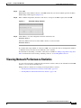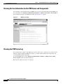
1
User Guide for Internetwork Performance
Monitor
Software Release 2.6
CiscoWorks
Corporate Headquarters
Cisco Systems, Inc.
170 West Tasman Drive
San Jose, CA 95134-1706
USA
http://www.cisco.com
Tel: 408 526-4000
800 553-NETS (6387)
Fax: 408 526-4100
Text Part Number: OL-11291-01
THE SPECIFICATIONS AND INFORMATION REGARDING THE PRODUCTS IN THIS MANUAL ARE SUBJECT TO CHANGE WITHOUT NOTICE. ALL
STATEMENTS, INFORMATION, AND RECOMMENDATIONS IN THIS MANUAL ARE BELIEVED TO BE ACCURATE BUT ARE PRESENTED WITHOUT
WARRANTY OF ANY KIND, EXPRESS OR IMPLIED. USERS MUST TAKE FULL RESPONSIBILITY FOR THEIR APPLICATION OF ANY PRODUCTS.
THE SOFTWARE LICENSE AND LIMITED WARRANTY FOR THE ACCOMPANYING PRODUCT ARE SET FORTH IN THE INFORMATION PACKET THAT
SHIPPED WITH THE PRODUCT AND ARE INCORPORATED HEREIN BY THIS REFERENCE. IF YOU ARE UNABLE TO LOCATE THE SOFTWARE LICENSE
OR LIMITED WARRANTY, CONTACT YOUR CISCO REPRESENTATIVE FOR A COPY.
The Cisco implementation of TCP header compression is an adaptation of a program developed by the University of California, Berkeley (UCB) as part of UCB’s public
domain version of the UNIX operating system. All rights reserved. Copyright © 1981, Regents of the University of California.
NOTWITHSTANDING ANY OTHER WARRANTY HEREIN, ALL DOCUMENT FILES AND SOFTWARE OF THESE SUPPLIERS ARE PROVIDED “AS IS” WITH
ALL FAULTS. CISCO AND THE ABOVE-NAMED SUPPLIERS DISCLAIM ALL WARRANTIES, EXPRESSED OR IMPLIED, INCLUDING, WITHOUT
LIMITATION, THOSE OF MERCHANTABILITY, FITNESS FOR A PARTICULAR PURPOSE AND NONINFRINGEMENT OR ARISING FROM A COURSE OF
DEALING, USAGE, OR TRADE PRACTICE.
IN NO EVENT SHALL CISCO OR ITS SUPPLIERS BE LIABLE FOR ANY INDIRECT, SPECIAL, CONSEQUENTIAL, OR INCIDENTAL DAMAGES, INCLUDING,
WITHOUT LIMITATION, LOST PROFITS OR LOSS OR DAMAGE TO DATA ARISING OUT OF THE USE OR INABILITY TO USE THIS MANUAL, EVEN IF CISCO
OR ITS SUPPLIERS HAVE BEEN ADVISED OF THE POSSIBILITY OF SUCH DAMAGES.
CCSP, CCVP, the Cisco Square Bridge logo, Follow Me Browsing, and StackWise are trademarks of Cisco Systems, Inc.; Changing the Way We Work, Live, Play, and Learn,
and iQuick Study are service marks of Cisco Systems, Inc.; and Access Registrar, Aironet, BPX, Catalyst, CCDA, CCDP, CCIE, CCIP, CCNA, CCNP, Cisco, the Cisco
Certified Internetwork Expert logo, Cisco IOS, Cisco Press, Cisco Systems, Cisco Systems Capital, the Cisco Systems logo, Cisco Unity, Enterprise/Solver, EtherChannel,
EtherFast, EtherSwitch, Fast Step, FormShare, GigaDrive, GigaStack, HomeLink, Internet Quotient, IOS, IP/TV, iQ Expertise, the iQ logo, iQ Net Readiness Scorecard,
LightStream, Linksys, MeetingPlace, MGX, the Networkers logo, Networking Academy, Network Registrar, Packet, PIX, Post-Routing, Pre-Routing, ProConnect,
RateMUX, ScriptShare, SlideCast, SMARTnet, The Fastest Way to Increase Your Internet Quotient, and TransPath are registered trademarks of Cisco Systems, Inc. and/or
its affiliates in the United States and certain other countries.
All other trademarks mentioned in this document or Website are the property of their respective owners. The use of the word partner does not imply a partnership relationship
between Cisco and any other company. (0601R)
User Guide for Internetwork Performance Monitor
Copyright © 1998-2006, Cisco Systems, Inc. All rights reserved.
CONTENTS
Preface
ix
Audience
ix
Conventions
ix
Product Documentation
x
Obtaining Documentation xi
Cisco.com xi
Product Documentation DVD xi
Ordering Documentation xi
Documentation Feedback
xii
Cisco Product Security Overview xii
Reporting Security Problems in Cisco Products
xii
Obtaining Technical Assistance xiii
Cisco Technical Support & Documentation Website
Submitting a Service Request xiv
Definitions of Service Request Severity xiv
Obtaining Additional Publications and Information
CHAPTER
1
Overview of IPM
What is IPM?
1-1
How Does IPM Work?
1-2
1-3
Client/Server Architecture
New Features in IPM 2.6
2
xiv
1-1
Key Terms and Concepts
CHAPTER
xiii
Getting Started With IPM
1-3
1-5
2-1
Starting IPM 2-1
Starting IPM Server on Solaris 2-1
Starting IPM Server on Windows 2-2
Starting IPM Client 2-2
Starting IPM Client From the CiscoWorks Homepage
2-2
User Guide for Internetwork Performance Monitor
OL-11291-01
iii
Contents
Starting IPM as a Standalone Client 2-3
Starting IPM Standalone Client on Solaris 2-3
Enabling the IPM Password on Solaris 2-5
Starting IPM Standalone Client on Windows 2-6
Starting IPM Client from the Windows Command Prompt
Enabling the IPM Password on Windows 2-7
Running Simultaneous IPM Sessions
2-6
2-8
Configuring the IPM Components 2-8
Defining a Source Device 2-8
Defining a Target 2-10
Defining a Collector 2-12
Viewing Network Performance Statistics 2-17
Viewing Network Performance Statistics in Real Time 2-18
Viewing Historical Network Performance Statistics 2-20
Understanding Next Range 2-26
Understanding Previous Range 2-26
CHAPTER
3
Printing IPM Statistics
2-27
Exiting the IPM Client
2-28
Using IPM to Measure Network Performance
3-1
Measuring Network Performance for DHCP
Defining a DHCP Operation 3-2
Viewing Statistics for DHCP 3-4
3-2
Measuring Network Performance for DLSw
Defining a DLSw Operation 3-5
Viewing Statistics for DLSw 3-7
3-5
Measuring Network Performance for DNS
Defining a DNS Operation 3-8
Viewing Statistics for DNS 3-9
3-8
Measuring Network Performance for HTTP
Defining an HTTP Operation 3-11
Viewing Statistics for HTTP 3-13
3-11
Measuring Network Performance for FTP
Defining an FTP Operation 3-15
Viewing Statistics for FTP 3-17
3-15
User Guide for Internetwork Performance Monitor
iv
OL-11291-01
Contents
Measuring Network Performance for IP 3-18
Measuring End-to-End Performance for IP 3-19
Defining an IP Echo Operation 3-19
Viewing End-to-End Statistics for IP 3-21
Measuring Hop-by-Hop Performance for IP 3-22
Defining an IP Path Echo Operation 3-22
Viewing Hop-by-Hop Statistics for IP 3-24
Measuring Network Performance for SNA 3-29
Defining an SNA Echo Operation 3-30
Viewing Statistics for SNA 3-31
Measuring Network Performance for TCP
Defining a TCP Operation 3-33
Viewing Statistics for TCP 3-35
3-33
Measuring Network Performance for UDP
Defining a UDP Operation 3-36
Viewing Statistics for UDP 3-38
3-36
Measuring Network Performance for Enhanced UDP
Defining an Enhanced UDP Operation 3-40
Viewing Statistics for Enhanced UDP 3-41
CHAPTER
4
Modifying IPM Components
3-39
4-1
Working With Source Devices 4-1
Viewing a List of Configured Source Devices
Viewing Source Properties 4-2
Adding a New Source Device 4-3
Deleting Source Devices 4-3
Working With Target Devices 4-3
Viewing a List of Defined Targets
Viewing Target Properties 4-4
Adding a New Target 4-5
Deleting Targets 4-5
4-2
4-4
Working With Operations 4-6
Viewing a List of Defined Operations 4-6
Viewing Operation Properties 4-8
Adding a New Operation 4-9
Setting Thresholds and Generating Alerts 4-9
Deleting Operations 4-11
User Guide for Internetwork Performance Monitor
OL-11291-01
v
Contents
Working With Collectors 4-11
Viewing a List of Defined Collectors 4-12
Viewing a Collector State Summary 4-12
Viewing Collector Properties 4-13
Adding a New Collector 4-14
Stopping Collectors 4-15
Deleting Collectors 4-15
Adding Components Using Seed Files 4-16
Creating a Seed File 4-16
Seed File Syntax 4-17
Sample Source Seed File 4-18
Sample Target Seed File 4-19
Sample Collector Seed File 4-19
Loading Components From a Seed File 4-21
Viewing Seed File Output Files 4-21
Changing IP Addresses
Setting the Baseline
4-22
4-23
Setting IPM Database Preferences 4-24
Displaying the Current Database Preferences
Changing the Database Preferences 4-25
Database Preferences File Format 4-27
4-25
Setting SNMP Timeout and Retry Environment Variables 4-29
Setting SNMP Environment Variables in Solaris 4-30
Setting SNMP Environment Variables in Windows 4-31
Setting New IPM Server Process Timeout Values 4-32
Setting Server Timeout Values in Solaris 4-33
Setting Server Timeout Values in Windows 4-33
Setting the DISPLAY Variable in Solaris
4-34
Backing Up or Restoring the IPM Database
NVRAM Settings
4-35
4-35
Managed Source Interface Settings
4-36
Changing Administrative Password
4-37
Changing IPM Database Password
4-37
Working With Message Log Window
Log Control 4-38
Log Display 4-39
4-38
User Guide for Internetwork Performance Monitor
vi
OL-11291-01
Contents
CHAPTER
5
Working With IPM From the CiscoWorks Homepage
5-1
Accessing IPM Data From the CiscoWorks Homepage
5-1
Viewing IPM Server Information 5-2
Viewing Status Information for IPM Servers 5-3
Viewing Version Information for the IPM Server and Components
Viewing the IPM Server Log 5-4
Viewing the IPM Console Log 5-5
Viewing the Troubleshooting Log for IPM 5-6
Importing Devices From Device and Credential Repository
5-4
5-7
Downloading the IPM Client 5-10
Downloading the IPM Client for Solaris 5-10
Downloading the IPM Client for Windows 5-11
Viewing Configuration Information 5-13
Viewing Source Configuration Information 5-13
Viewing Target Configuration Information 5-14
Viewing Operation Configuration Information 5-14
Viewing Collector Configuration Information 5-15
Viewing Path Echo Collector Path Usage Data 5-16
Viewing Latency Data 5-17
Viewing Daily Latency Data 5-18
Viewing Weekly Latency Data 5-21
Viewing Monthly Latency Data 5-22
Viewing Jitter Data 5-23
Viewing Daily Jitter Data 5-23
Viewing Weekly Jitter Data 5-25
Viewing Monthly Jitter Data 5-26
Viewing HTTP Data 5-27
Viewing Daily HTTP Data 5-27
Viewing Weekly HTTP Data 5-28
Viewing Monthly HTTP Data 5-29
Accessing Software Updates and Additional Information 5-30
Viewing Information About IPM on Cisco.com 5-30
APPENDIX
A
IPM FAQs and Troubleshooting Tips
IPM FAQs
A-1
A-1
Troubleshooting IPM
A-11
User Guide for Internetwork Performance Monitor
OL-11291-01
vii
Contents
APPENDIX
B
IPM Command Reference
B-1
Output of ipm status Command
Output of ipm help Command
B-8
B-8
Output of ipm export help Command
IPM Internal Commands
APPENDIX
C
B-11
B-13
SA Agent Feature Mapping C-1
Verify Your SA Agent Version
C-2
GLOSSARY
INDEX
User Guide for Internetwork Performance Monitor
viii
OL-11291-01
Preface
This document describes how to use Internetwork Performance Monitor (IPM) 2.6, a software to monitor
the performance of multi-protocol networks. This preface describes who should read this guide, and
outlines the document conventions used in this guide.
Audience
This document is for the network administrator or operator who uses the Internetwork Performance
Monitor software. Network administrators or operators should have:
•
Basic network management skills
•
Basic Windows system administrator skills
•
Basic Solaris system administrator skills
Conventions
This document uses the following conventions:
Note
Item
Convention
Commands and keywords
boldface font
Variables for which you supply values
italic font
Displayed session and system information
screen
Information you enter
boldface screen font
Variables you enter
italic screen
Menu items and button names
boldface font
Selecting a menu item in paragraphs
Option > Network Preferences
Selecting a menu item in tables
Option > Network Preferences
font
font
Means reader take note. Notes contain helpful suggestions or references to material not covered in the
publication.
User Guide for Internetwork Performance Monitor
OL-11291-01
ix
Preface
Product Documentation
Caution
Warning
Means reader be careful. In this situation, you might do something that could result in equipment
damage or loss of data.
This symbol means danger. You are in a situation that could cause bodily injury.
Product Documentation
Note
We sometimes update the printed and electronic documentation after original publication. Therefore,
you should also review the documentation on Cisco.com for any updates.
Table 1 describes the product documentation that is available.
Table 1
Product Documentation
Document Title
Available Formats
Release Notes for Internetwork
Performance Monitor 2.6
•
On Cisco.com at this URL:
http://www.cisco.com/en/US/products/sw/cscowork/ps1008/prod_release_note0
9186a008035c18b.html
Installation Guide for Internetwork
Performance Monitor 2.6
•
PDF on the documentation CD-ROM.
•
On Cisco.com at this URL:
http://www.cisco.com/en/US/products/sw/cscowork/ps1008/products_installatio
n_guide_book09186a0080366ce9.html
User Guide for Internetwork
Performance Monitor 2.6
•
PDF on the documentation CD-ROM.
•
On Cisco.com at this URL:
http://www.cisco.com/en/US/products/sw/cscowork/ps1008/products_user_guid
e_book09186a0080366cf7.html
Context-sensitive online help
•
Select an option from the navigation tree, then click Help.
•
Click the Help button in the dialog box.
User Guide for Internetwork Performance Monitor
x
OL-11291-01
Preface
Obtaining Documentation
Obtaining Documentation
Cisco documentation and additional literature are available on Cisco.com. Cisco also provides several
ways to obtain technical assistance and other technical resources. These sections explain how to obtain
technical information from Cisco Systems.
Cisco.com
You can access the most current Cisco documentation at this URL:
http://www.cisco.com/techsupport
You can access the Cisco website at this URL:
http://www.cisco.com
You can access international Cisco websites at this URL:
http://www.cisco.com/public/countries_languages.shtml
Product Documentation DVD
Cisco documentation and additional literature are available in the Product Documentation DVD package,
which may have shipped with your product. The Product Documentation DVD is updated regularly and
may be more current than printed documentation.
The Product Documentation DVD is a comprehensive library of technical product documentation on
portable media. The DVD enables you to access multiple versions of hardware and software installation,
configuration, and command guides for Cisco products and to view technical documentation in HTML.
With the DVD, you have access to the same documentation that is found on the Cisco website without
being connected to the Internet. Certain products also have .pdf versions of the documentation available.
The Product Documentation DVD is available as a single unit or as a subscription. Registered Cisco.com
users (Cisco direct customers) can order a Product Documentation DVD (product number
DOC-DOCDVD=) from Cisco Marketplace at this URL:
http://www.cisco.com/go/marketplace/
Ordering Documentation
Beginning June 30, 2005, registered Cisco.com users may order Cisco documentation at the Product
Documentation Store in the Cisco Marketplace at this URL:
http://www.cisco.com/go/marketplace/
Nonregistered Cisco.com users can order technical documentation from 8:00 a.m. to 5:00 p.m.
(0800 to 1700) PDT by calling 1 866 463-3487 in the United States and Canada, or elsewhere by
calling 011 408 519-5055. You can also order documentation by e-mail at
[email protected] or by fax at 1 408 519-5001 in the United States and Canada,
or elsewhere at 011 408 519-5001.
User Guide for Internetwork Performance Monitor
OL-11291-01
xi
Preface
Documentation Feedback
Documentation Feedback
You can rate and provide feedback about Cisco technical documents by completing the online feedback
form that appears with the technical documents on Cisco.com.
You can send comments about Cisco documentation to [email protected].
You can submit comments by using the response card (if present) behind the front cover of your
document or by writing to the following address:
Cisco Systems
Attn: Customer Document Ordering
170 West Tasman Drive
San Jose, CA 95134-9883
We appreciate your comments.
Cisco Product Security Overview
Cisco provides a free online Security Vulnerability Policy portal at this URL:
http://www.cisco.com/en/US/products/products_security_vulnerability_policy.html
From this site, you can perform these tasks:
•
Report security vulnerabilities in Cisco products.
•
Obtain assistance with security incidents that involve Cisco products.
•
Register to receive security information from Cisco.
A current list of security advisories and notices for Cisco products is available at this URL:
http://www.cisco.com/go/psirt
If you prefer to see advisories and notices as they are updated in real time, you can access a Product
Security Incident Response Team Really Simple Syndication (PSIRT RSS) feed from this URL:
http://www.cisco.com/en/US/products/products_psirt_rss_feed.html
Reporting Security Problems in Cisco Products
Cisco is committed to delivering secure products. We test our products internally before we release them,
and we strive to correct all vulnerabilities quickly. If you think that you might have identified a
vulnerability in a Cisco product, contact PSIRT:
•
Emergencies — [email protected]
An emergency is either a condition in which a system is under active attack or a condition for which
a severe and urgent security vulnerability should be reported. All other conditions are considered
nonemergencies.
•
Nonemergencies — [email protected]
In an emergency, you can also reach PSIRT by telephone:
•
1 877 228-7302
•
1 408 525-6532
User Guide for Internetwork Performance Monitor
xii
OL-11291-01
Preface
Obtaining Technical Assistance
Tip
We encourage you to use Pretty Good Privacy (PGP) or a compatible product to encrypt any sensitive
information that you send to Cisco. PSIRT can work from encrypted information that is compatible with
PGP versions 2.x through 8.x.
Never use a revoked or an expired encryption key. The correct public key to use in your correspondence
with PSIRT is the one linked in the Contact Summary section of the Security Vulnerability Policy page
at this URL:
http://www.cisco.com/en/US/products/products_security_vulnerability_policy.html
The link on this page has the current PGP key ID in use.
Obtaining Technical Assistance
Cisco Technical Support provides 24-hour-a-day award-winning technical assistance. The Cisco
Technical Support & Documentation website on Cisco.com features extensive online support resources.
In addition, if you have a valid Cisco service contract, Cisco Technical Assistance Center (TAC)
engineers provide telephone support. If you do not have a valid Cisco service contract, contact your
reseller.
Cisco Technical Support & Documentation Website
The Cisco Technical Support & Documentation website provides online documents and tools for
troubleshooting and resolving technical issues with Cisco products and technologies. The website is
available 24 hours a day, at this URL:
http://www.cisco.com/techsupport
Access to all tools on the Cisco Technical Support & Documentation website requires a Cisco.com user
ID and password. If you have a valid service contract but do not have a user ID or password, you can
register at this URL:
http://tools.cisco.com/RPF/register/register.do
Note
Use the Cisco Product Identification (CPI) tool to locate your product serial number before submitting
a web or phone request for service. You can access the CPI tool from the Cisco Technical Support &
Documentation website by clicking the Tools & Resources link under Documentation & Tools. Choose
Cisco Product Identification Tool from the Alphabetical Index drop-down list, or click the Cisco
Product Identification Tool link under Alerts & RMAs. The CPI tool offers three search options: by
product ID or model name; by tree view; or for certain products, by copying and pasting show command
output. Search results show an illustration of your product with the serial number label location
highlighted. Locate the serial number label on your product and record the information before placing a
service call.
User Guide for Internetwork Performance Monitor
OL-11291-01
xiii
Preface
Obtaining Additional Publications and Information
Submitting a Service Request
Using the online TAC Service Request Tool is the fastest way to open S3 and S4 service requests. (S3
and S4 service requests are those in which your network is minimally impaired or for which you require
product information.) After you describe your situation, the TAC Service Request Tool provides
recommended solutions. If your issue is not resolved using the recommended resources, your service
request is assigned to a Cisco engineer. The TAC Service Request Tool is located at this URL:
http://www.cisco.com/techsupport/servicerequest
For S1 or S2 service requests or if you do not have Internet access, contact the Cisco TAC by telephone.
(S1 or S2 service requests are those in which your production network is down or severely degraded.)
Cisco engineers are assigned immediately to S1 and S2 service requests to help keep your business
operations running smoothly.
To open a service request by telephone, use one of the following numbers:
Asia-Pacific: +61 2 8446 7411 (Australia: 1 800 805 227)
EMEA: +32 2 704 55 55
USA: 1 800 553-2447
For a complete list of Cisco TAC contacts, go to this URL:
http://www.cisco.com/techsupport/contacts
Definitions of Service Request Severity
To ensure that all service requests are reported in a standard format, Cisco has established severity
definitions.
Severity 1 (S1)—Your network is “down,” or there is a critical impact to your business operations. You
and Cisco will commit all necessary resources around the clock to resolve the situation.
Severity 2 (S2)—Operation of an existing network is severely degraded, or significant aspects of your
business operation are negatively affected by inadequate performance of Cisco products. You and Cisco
will commit full-time resources during normal business hours to resolve the situation.
Severity 3 (S3)—Operational performance of your network is impaired, but most business operations
remain functional. You and Cisco will commit resources during normal business hours to restore service
to satisfactory levels.
Severity 4 (S4)—You require information or assistance with Cisco product capabilities, installation, or
configuration. There is little or no effect on your business operations.
Obtaining Additional Publications and Information
Information about Cisco products, technologies, and network solutions is available from various online
and printed sources.
•
Cisco Marketplace provides a variety of Cisco books, reference guides, documentation, and logo
merchandise. Visit Cisco Marketplace, the company store, at this URL:
http://www.cisco.com/go/marketplace/
User Guide for Internetwork Performance Monitor
xiv
OL-11291-01
Preface
Obtaining Additional Publications and Information
•
Cisco Press publishes a wide range of general networking, training and certification titles. Both new
and experienced users will benefit from these publications. For current Cisco Press titles and other
information, go to Cisco Press at this URL:
http://www.ciscopress.com
•
Packet magazine is the Cisco Systems technical user magazine for maximizing Internet and
networking investments. Each quarter, Packet delivers coverage of the latest industry trends,
technology breakthroughs, and Cisco products and solutions, as well as network deployment and
troubleshooting tips, configuration examples, customer case studies, certification and training
information, and links to scores of in-depth online resources. You can access Packet magazine at
this URL:
http://www.cisco.com/packet
•
iQ Magazine is the quarterly publication from Cisco Systems designed to help growing companies
learn how they can use technology to increase revenue, streamline their business, and expand
services. The publication identifies the challenges facing these companies and the technologies to
help solve them, using real-world case studies and business strategies to help readers make sound
technology investment decisions. You can access iQ Magazine at this URL:
http://www.cisco.com/go/iqmagazine
or view the digital edition at this URL:
http://ciscoiq.texterity.com/ciscoiq/sample/
•
Internet Protocol Journal is a quarterly journal published by Cisco Systems for engineering
professionals involved in designing, developing, and operating public and private internets and
intranets. You can access the Internet Protocol Journal at this URL:
http://www.cisco.com/ipj
•
Networking products offered by Cisco Systems, as well as customer support services, can be
obtained at this URL:
http://www.cisco.com/en/US/products/index.html
•
Networking Professionals Connection is an interactive website for networking professionals to share
questions, suggestions, and information about networking products and technologies with Cisco
experts and other networking professionals. Join a discussion at this URL:
http://www.cisco.com/discuss/networking
•
World-class networking training is available from Cisco. You can view current offerings at
this URL:
http://www.cisco.com/en/US/learning/index.html
User Guide for Internetwork Performance Monitor
OL-11291-01
xv
Preface
Obtaining Additional Publications and Information
User Guide for Internetwork Performance Monitor
xvi
OL-11291-01
C H A P T E R
1
Overview of IPM
This chapter provides an overview of Internetwork Performance Monitor (IPM) application. It contains
the following sections:
•
What is IPM?
•
Key Terms and Concepts
•
How Does IPM Work?
•
Client/Server Architecture
What is IPM?
IPM is a network management application that allows you to monitor the performance of multi-protocol
networks. IPM measures the latency and availability of IP networks on a hop-by-hop (router-to-router)
basis. It also measures latency between routers and the mainframe in Systems Network Architecture
(SNA) networks, and monitors jitter in networks.
You can use IPM to:
•
Troubleshoot problems by checking the network performance between devices.
•
Send Simple Network Management Protocol (SNMP) traps and SNA alerts when a user-configured
threshold is exceeded, a connection is lost and reestablished, or a timeout occurs.
•
Analyze potential problems before they occur by accumulating statistics, which then can be used to
model and design future network topologies.
•
Monitor latency, availability, and errors between two network end points.
•
Monitor jitter, packet loss, and errors between two network end points.
•
Discover network paths between two network end points, and monitor network performance
statistics on a hop-by-hop basis.
•
Provide Web-based access to long-term information to help determine statistical trends.
•
Monitor the availability of critical network servers.
•
Monitor SNA performance in mainframe environments.
•
Establish service-level agreements.
User Guide for Internetwork Performance Monitor
OL-11291-01
1-1
Chapter 1
Overview of IPM
Key Terms and Concepts
The IPM/SA Agent monitoring solution is composed of:
1.
The IPM server
2.
The IPM client application
3.
The Service Assurance (SA) Agent feature of the Cisco IOS software
The focus of this document is the IPM network management application, which includes the server and
the client. In some cases, however, it is not possible to fully describe IPM without including information
about the SA Agent feature. Therefore, we have included some information about the Cisco IOS feature.
Information about the SA Agent feature, provided in the latest Cisco IOS software documentation takes
precedence over the information about the SA Agent feature, contained in this document.
Key Terms and Concepts
The key terms and concepts in IPM are:
•
Network Performance Statistics—Five key statistics measured by IPM:
– Latency
– Availability
– Jitter
– Packet Loss
– Errors
•
Source—Originating switch or router running IOS, from which IPM makes network performance
measurements. The source switch or router must be running a version of Cisco IOS software that
supports the SA Agent feature. For detailed information about the supported versions of the Cisco
IOS software, see the “Cisco IOS Software Requirements” section in the Installation Guide for
Internetwork Performance Monitor.
•
Target—Destination of the network performance measurements. The target can be any
IP-addressable device, an IBM Multiple Virtual Storage (MVS) mainframe that can be reached by
the source router, or an SA Agent-enabled Cisco router. For jitter measurements, the target must be
an SA Agent-enabled Cisco router or switch with RTR responder enabled.
•
Operation—Set of parameters used in measuring network performance statistics. The parameters
specify the type of measurement to be performed.
•
Collector—Entity defined to measure network performance statistics from a specific source device
to a specific target device. The collector definition includes information about its source, target,
operation, start time, duration, and type.
•
Interval—How often, in seconds, the collector on the source router executes the measurement to
and from the target. The value is usually every 60 seconds. The valid range is 10 to 3600 seconds (1
hour). The source router automatically aggregates all samples for a single hour into a single set of
metrics for that hour. IPM retrieves these metrics from the source router once every hour.
•
Duration—How long, in days, hours, and minutes, the collector runs and gathers information from
the source router. The default value is forever. The valid range is 1 hour to forever.
•
SA Agent Responder—Component embedded in a target Cisco device, running version 12.1 or
later of the Cisco IOS software. It responds to SA Agent request packets from a source running the
SA Agent software, supporting Enhanced UDP measurements, such as jitter.
User Guide for Internetwork Performance Monitor
1-2
OL-11291-01
Chapter 1
Overview of IPM
How Does IPM Work?
How Does IPM Work?
IPM measures and displays network performance statistics (latency, availability, jitter, packet loss, and
error information) between a source and a target device.
The target can be an IP-addressable device, an IBM MVS mainframe, or an SA Agent-enabled Cisco
router:
•
If the target is an IP-addressable device, it can be a network device, a server, or a workstation.
•
If the target is an IBM MVS mainframe, it must be running an IPM Virtual Telecommunications
Access Method (VTAM) application called NSPECHO for measuring SNA latency. See the
“Installing NSPECHO to Measure SNA Response Times” chapter of the Installation Guide for
Internetwork Performance Monitor for more information.
•
If the target is an SA Agent-enabled, the source must be running version 12.1 or later of the Cisco
IOS software. The IPM application is used to configure the SA Agent in each source device. The
SA Agent measures the performance between the source router and the target device.
The source aggregates all measurements into a single sample value for each network performance
statistic. IPM gathers the data from the source and stores it in the IPM database.
IPM also provides a real-time feature that allows you to display the data without waiting for the one-hour
data collection interval. However, the data displayed in the Real Time window is not stored in the IPM
database.
Additionally, IPM provides an extensive set of reports and graphs for viewing and analyzing the
collected performance metrics. IPM supports both standalone and Web-based clients in a multi-platform
environment.
Client/Server Architecture
IPM provides central services and database functions on an IPM server, which communicates through a
messaging interface to multiple IPM clients (Figure 1-1). The IPM software consists of server software
and client software components that can be installed on the same workstation or on different
workstations.
User Guide for Internetwork Performance Monitor
OL-11291-01
1-3
Chapter 1
Overview of IPM
Client/Server Architecture
Figure 1-1
IPM Client/Server Architecture
Solaris or Windows 2000 System
(IPM server, client, and database)
IPM client on
Windows 2000 workstation
IPM client on
Windows XP workstation
IPM client on
Solaris workstation
85632
Network
For this release of IPM, the server software runs on Solaris 2.8, Solaris 2.9, and Windows 2000
Professional and Server (with SP3 or SP4), Windows 2000 Advanced Server (with SP3 or SP4),
Windows 2000 Terminal Services Remote Administration Mode (with SP3 or SP4) or Windows 2003.
The client software runs on Solaris 2.8, Solaris 2.9, Windows 2000 Professional and Server (with SP3
and SP4), Windows XP Professional (with SP1a) or Windows 2003 platforms.
The client/server architecture is cross-platform compatible, which allows you to run the client and server
software in mixed operating system environments. For example, you can run the IPM server on a Solaris
workstation and access it from an IPM client running on a Windows workstation.
Note
IPM does not support Network Address Translation (NAT) and Port Address Translation (PAT) between
the client and the server.
The IPM server software consists of a group of functional services that manage the data among the
network, client workstations, and the centralized database.
The IPM server manages the exchange of data between the IPM database and the network devices, such
as the source routers. The IPM process manager launches and manages all of the IPM servers, providing
a robust and reliable launching platform for IPM.
The IPM client integrates with the CiscoWorks homepage.
From a Web browser running on a Solaris 2.8, Solaris 2.9, Windows 2000 Professional and Server (with
SP3 and SP4), Windows XP Professional (with SP1a) or Windows 2003 platforms workstation on the
network, you can:
•
Access the source, target, operation, and collector definitions.
•
View Web-based reports of the performance metrics.
User Guide for Internetwork Performance Monitor
1-4
OL-11291-01
Chapter 1
Overview of IPM
New Features in IPM 2.6
•
Download/Launch the IPM client.
•
View Web-based troubleshooting information.
•
Determine the version of IPM that has been installed.
•
View seed files.
All the above functions can be launched via the CiscoWorks homepage.
New Features in IPM 2.6
These are the new features in IPM 2.6:
•
Support for importing device from Device and Credential Repository — IPM 2.6 provides you the
facility to import devices from the Device and Credential Repository. You can import devices as
Sources, as Target SAA Responders, or as Target IP Devices.
•
Differentiated Service Code Point (DSCP) support — In IPM 2.6 users are provided with the feature
of selecting either the IP Precedence settings or DSCP setting.
•
Source interface on collector — In the earlier IPM releases, users could not specify a source
interface configuration on an individual collector basis while configuring a collector. IPM 2.6 has
features to overcome this limitation.
•
Device Center Integration — In IPM 2.6, the Device Center will be launched for devices in IPM.
The Device Center will be launched irrespective of whether a device is present in Device and
Credential Repository or not.
•
Improved Scalability— IPM 2.6 supports 2000 collectors in one single IPM Server.
•
SSL Compliance — IPM 2.6 is SSL compliant and enables secure HTTP communication between
the client and server. The IPM web links from the CiscoWorks homepage are SSL-compliant.
User Guide for Internetwork Performance Monitor
OL-11291-01
1-5
Chapter 1
Overview of IPM
New Features in IPM 2.6
User Guide for Internetwork Performance Monitor
1-6
OL-11291-01
C H A P T E R
2
Getting Started With IPM
This chapter provides information about starting the IPM application and configuring a collector to
gather latency data. It includes the following major sections:
•
Starting IPM
•
Running Simultaneous IPM Sessions
•
Configuring the IPM Components
•
Viewing Network Performance Statistics
•
Printing IPM Statistics
•
Exiting the IPM Client
Starting IPM
Since the IPM application is comprised of a server component and a client component, you must start
both components to run the application. If the IPM server and client are installed on the same system,
you can start the IPM server and client using a single command, or you can start them separately.
The following sections provide details for starting the IPM server and client:
•
Starting IPM Server on Solaris
•
Starting IPM Server on Windows
•
Starting IPM Client From the CiscoWorks Homepage
•
Starting IPM Standalone Client on Solaris
•
Starting IPM Standalone Client on Windows
Starting IPM Server on Solaris
To start the IPM server on a Solaris system, enter:
# cd /opt/CSCOipm/bin
# ./ipm start
To enter the ipm start command, you must be logged in as the root user, or your login must have
administrator privileges.
User Guide for Internetwork Performance Monitor
OL-11291-01
2-1
Chapter 2
Getting Started With IPM
Starting IPM Client
Starting IPM Server on Windows
To start the IPM server on a Windows system, enter:
cd c:\Program Files\Internetwork Performance Monitor\Server\bin
ipm start
To enter the ipm start command, you must be logged in as the administrator, or your login must have
administrator privileges.
Starting IPM Client
You can access the IPM Client in two ways: As a web client from the CiscoWorks homepage, or as a
standalone client.
This section describes:
•
Starting IPM Client From the CiscoWorks Homepage
•
Starting IPM as a Standalone Client
Starting IPM Client From the CiscoWorks Homepage
You can start IPM from an Internet Explorer or Netscape Navigator Web browser if:
•
You are running Solaris 2.8, Solaris 2.9, Windows XP Professional and Server (with SP3, SP4),
Windows 2000 Advanced Server (with SP3, SP4)
Windows 2000 Terminal Services Remote Administration mode (with SP3, SP4) or Windows 2003
Server (Standard Edition and Enterprise Edition).
•
You have installed the Java plug-in 1.4.2-04. (For information about installing the Java plug-in, see
the “Installing IPM on Windows” chapter of the Installation Guide for Internetwork Performance
Monitor.)
To start the IPM client from the CiscoWorks homepage:
Step 1
Make sure the IPM server to which you are connecting is currently running.
Step 2
From your browser, go to the URL where the IPM application is installed (for example,
http://youripmserver:1741).
The homepage for the IPM Client Software appears (Figure 2-1).
User Guide for Internetwork Performance Monitor
2-2
OL-11291-01
Chapter 2
Getting Started With IPM
Starting IPM Client
Figure 2-1
IPM CiscoWorks Homepage
If you do not have this URL, contact the system administrator who installed the IPM server software.
Step 3
Select Client > Web Client.
The Java applet loads and the IPM Main Window is displayed.
The IPM Main Window is the starting point from where you can carry out the various IPM operations.
In addition to and accessing the IPM Main Window from the CiscoWorks homepage, you can also launch
the IPM Main Window from a standalone Solaris or a Windows client.
For details on starting IPM on Solaris, see Starting IPM Standalone Client on Solaris, page 2-3. For
details on starting IPM on Windows, see Starting IPM Standalone Client on Windows, page 2-6.
Starting IPM as a Standalone Client
This section describes the following:
•
Starting IPM Standalone Client on Solaris
•
Starting IPM Standalone Client on Windows
Starting IPM Standalone Client on Solaris
To start only the IPM client on a Solaris system, enter:
# cd /opt/CSCOipm/bin
# ./ipm start client
To start the IPM server and client on a Solaris system, enter:
# cd /opt/CSCOipm/bin
# ./ipm
User Guide for Internetwork Performance Monitor
OL-11291-01
2-3
Chapter 2
Getting Started With IPM
Starting IPM Client
The default directory for installing IPM is /opt. If you installed IPM in a different directory, you must
specify that directory instead of /opt.
If you installed the IPM client and IPM server on different Solaris systems, you must enter the ipm start
command from the /opt/CSCOipmClient/bin directory:
# cd /opt/CSCOipmClient/bin
# ./ipm start client
To start the IPM client and connect to an IPM server other than the default server, enter:
# cd /opt/CSCOipmClient/bin
# ./ipm start client server_name
where server_name is the Solaris or Windows system on which the IPM server is running.
To protect the device credentials, IPM does not allow you to disable the administrative password. IPM
will prompt you to enter the password at the time of launching the standalone client.
When the IPM client starts, it displays the IPM Main Window (Figure 2-2). The name of the system on
which the IPM server is running, appears in the title bar of the IPM Main Window.
Figure 2-2
IPM Main Window
You can also access the IPM Main Window from the CiscoWorks homepage. For more details, see
Starting IPM Client From the CiscoWorks Homepage, page 2-2. Alternatively, you can click View >
CiscoWorks Home Page to access the CiscoWorks homepage.
When you start IPM for the first time, the IPM Main Window contains no collectors. As you configure
collectors, they appear in this window. Each collector is a combination of a configured source, a target,
and an operation. For each collector, you can specify parameters for gathering statistics and scheduling.
User Guide for Internetwork Performance Monitor
2-4
OL-11291-01
Chapter 2
Getting Started With IPM
Starting IPM Client
Enabling the IPM Password on Solaris
To enable IPM passwords on Solaris:
Step 1
Log in as the root user.
Step 2
Enter:
# cd /opt/CSCOipm/bin
# ./ipm password
Note
The default directory for installing IPM is /opt. If you installed IPM in a different directory, you
must specify that directory instead of /opt.
IPM prompts you to enter a password.
Step 3
Enter a password and press Enter.
The password is case sensitive and should begin with an alphabet. You can enter only a maximum of 15
characters and you can enter only alphanumeric characters.
IPM prompts you to confirm the password.
Step 4
Enter the password again and press Enter.
IPM displays:
IPM Administrative Password is Changed.
Use IPM Administrative Password to access standalone IPM Client and CLI commands
The administrative password is required for launching the IPM standalone client.
Note
To protect device credentials IPM does not allow you to disable the administrative password. During
IPM installation, you will be prompted to enter the administrative password. It is important that you set
the administrative password.
User Guide for Internetwork Performance Monitor
OL-11291-01
2-5
Chapter 2
Getting Started With IPM
Starting IPM Client
Starting IPM Standalone Client on Windows
When you install the IPM client on a Windows 2000 Professional and Server (with SP3 and SP4),
Windows 2000 Advanced Server (with SP3, SP4), Windows XP Pro (SP1a) or Windows 2000 (WS2K3)
system, the installation program adds two icons to your desktop: one icon for connecting to the IPM
server you specified during installation, and one icon for connecting to any IPM server.
To start the IPM client on a Windows system and connect to the default IPM server:
Step 1
Make sure the IPM server to which you are connecting is currently running.
Step 2
Double-click on the IPM client icon on your desktop.
The IPM client starts and displays the IPM Main Window (Figure 2-2).
You can also access the IPM Main Window from the CiscoWorks homepage. For more details, see
Starting IPM Client From the CiscoWorks Homepage, page 2-2. Alternatively, you can click View >
CiscoWorks Home Page to access the CiscoWorks homepage.
To start the IPM client on a Windows system and connect to any IPM server:
Step 1
Make sure the IPM server to which you are connecting is currently running.
Step 2
Double-click on the IPM Any Server icon on your desktop.
A prompt appears asking you for the name of the IPM server to which you want to connect.
Step 3
Enter the IPM server name and click OK.
The IPM client starts and displays the IPM Main Window (Figure 2-2)
Starting IPM Client from the Windows Command Prompt
To start the IPM server and client from the command prompt on a Windows system, enter:
cd c:\Program Files\Internetwork Performance Monitor\Server\bin
ipm
The default directory for installing IPM is C:\Program Files\Internetwork Performance Monitor\. If you
installed IPM in a different directory, you must specify that directory instead of C:\Program
Files\Internetwork Performance Monitor\.
To start only the IPM client on a Windows system, enter:
cd c:\Program Files\Internetwork Performance Monitor\Server\bin
ipm start client
If you installed the IPM client and IPM server on different Windows systems, you must enter the ipm
start command from the c:\Program Files\Internetwork Performance Monitor\client\bin directory:
cd c:\Program Files\Internetwork Performance Monitor\client\bin
ipm start client
User Guide for Internetwork Performance Monitor
2-6
OL-11291-01
Chapter 2
Getting Started With IPM
Starting IPM Client
To start the IPM client and connect to an IPM server other than the default server, enter:
cd c:\Program Files\Internetwork Performance Monitor\client\bin
ipm start client server_name
where server_name is the Solaris or Windows system on which the IPM server is running.
Note
To protect IPM device credentials, IPM does not allow you to disable the administrative password. IPM
will prompt you to enter the password when you launch the client.
When the IPM client starts, it displays the IPM Main Window (Figure 2-2). The name of the system on
which the IPM server is running appears in the title bar of the IPM Main Window.
When you start IPM for the first time, the IPM Main Window contains no collectors. As you configure
collectors, they are displayed in the window. Each collector is a combination of a configured source, a
target, and an operation. For each collector, you can specify parameters for gathering statistics and
scheduling.
Enabling the IPM Password on Windows
To enable an IPM password on Windows:
Step 1
Log in as the administrator.
Step 2
Enter:
cd c:\Program Files\Internetwork Performance Monitor\Server\bin
ipm password
The default directory for installing IPM is c:\Program Files\Internetwork Performance Monitor. If you
installed IPM in a different directory, specify that directory instead of c:\Program Files\Internetwork
Performance Monitor.
IPM prompts you to enter a password.
Step 3
Enter a password and press Enter.
The password is case sensitive and should begin with an alphabet. You can enter only a maximum of 15
characters and you can enter only alphanumeric characters.
IPM prompts you to confirm the password.
Step 4
Enter the password again and press Enter.
IPM displays:
IPM Administrative Password is Changed.
Use IPM Administrative Password to access standalone IPM Client and CLI commands
The Administrative password is required for launching the IPM standalone Client.
Note
To protect device credentials, IPM does not allow you to disable the administrative password. During
IPM installation, you will be prompted to enter the administrative password. It is important that you set
the administrative password.
User Guide for Internetwork Performance Monitor
OL-11291-01
2-7
Chapter 2
Getting Started With IPM
Running Simultaneous IPM Sessions
Running Simultaneous IPM Sessions
IPM allows you to run multiple sessions of the IPM client simultaneously. Central services and database
functions are provided on an IPM server that communicates to multiple IPM clients. You can install the
IPM client software on the same system as the IPM server, or on a different system on the same network
as the IPM server.
Running more than one IPM client on the same workstation can degrade the workstation’s performance.
Configuring the IPM Components
To collect network performance metrics using IPM, you must define a collector in a source router. A
collector is a definition of a source router, a target device, an operation, and a collector schedule.
To define a collector, complete the following tasks:
•
Defining a Source Device
•
Defining a Target
•
Defining a Collector
Defining a Source Device
IPM source devices are the devices from which packets are sent to measure and store statistical data,
including network latency, jitter, availability, packet loss, and errors. Each source device must contain
the Cisco IOS software SA Agent feature.
The types of operations you can use are determined by the version of the Cisco IOS software running on
the source device. IPM automatically checks the Cisco IOS software version on the device and limits the
creation of operations to those supported by the source device.
For information about the recommended versions of Cisco IOS software to use with IPM, see the “Cisco
IOS Software Requirements” section of the Installation Guide for Internetwork Performance Monitor.
To define a new source router:
Step 1
Verify that the SNMP read community and write community strings are configured properly on the
router.
If you want to receive traps at your network management system (NMS), verify that the router is
configured to send SA Agent-generated traps to your NMS.
For information about trap configuration on the source router, see the “Configuring Your Routers to Send
SA Agent-Related Traps” section in the “Preparing to Install” chapter of the Installation Guide for
Internetwork Performance Monitor.
Step 2
From the IPM Main Window (Figure 2-2), select Edit > Configuration.
The Configuration window (Figure 2-3) appears. By default, Sources is selected in the navigation pane
and the Source Configuration window appears within the Configuration window.
User Guide for Internetwork Performance Monitor
2-8
OL-11291-01
Chapter 2
Getting Started With IPM
Configuring the IPM Components
Figure 2-3
Configuration Window—Source Configuration
Step 3
In the Hostname or IP Address field, enter the host name or IP address of the device to use as the source
for network performance measurements. This host name can be from 1 to 64 characters in length.
Step 4
In the Read Community field, enter the SNMP community name for read access to the information
maintained by the SNMP agent on the source device. This value can be from 1 to 255 characters in
length.
Step 5
In the Write Community field, enter the SNMP community name for write access to the information
maintained by the SNMP agent on the source device. This value can be from 1 to 255 characters in
length.
Step 6
In the Alias Name field, enter a name to assign to the source router. By default, this field matches the
Hostname or IP Address field, but you can modify the name (for example, to use as an alias). In the
Description field, you can enter a brief description of the source router.
Step 7
Click Add.
IPM attempts to locate the source and determine whether or not it is SNMP-enabled with the correct
Read and Write community string. If the router is successfully located, IPM adds it to the IPM database.
If IPM cannot reach the router, IPM displays an error message.
Note
Step 8
If you specify an IP address instead of a host name, and that IP address cannot be resolved by
standard address resolution techniques, then IPM assumes that the IP address is valid and does
not resolve to a host name.
Click OK to close the Configuration window and return to the IPM Main Window.
User Guide for Internetwork Performance Monitor
OL-11291-01
2-9
Chapter 2
Getting Started With IPM
Configuring the IPM Components
If you must add a large number of source routers to IPM, you can use the Source Configuration window
to add them one by one, but it is more efficient to use a seed file. For information about using a seed file
to add source routers to IPM, see the “Adding Components Using Seed Files” section on page 4-16. For
information about viewing or deleting source routers, see the “Working With Source Devices” section
on page 4-1.
Defining a Target
IPM targets are destination devices for which you want to gather data. A target can be any IP-addressable
device, an SA Agent Responder, or an SNA host.
To define a device as a target:
Step 1
Select Edit > Configuration from the IPM Main Window (Figure 2-2).
The Configuration window (Figure 2-3) appears.
Step 2
Click Targets.
The Target Configuration window(Figure 2-4) appears within the Configuration window.
Figure 2-4
Target Configuration Window
User Guide for Internetwork Performance Monitor
2-10
OL-11291-01
Chapter 2
Getting Started With IPM
Configuring the IPM Components
Step 3
In the Target Type field, select the protocol type to be used with this target. The possible values are:
•
IP—Any IP-addressable device. Requires a destination IP address or host name.
•
Cisco SAA Responder—Component embedded in a target Cisco device running version 12.1 or later
of the Cisco IOS software. Its function is to respond to SA Agent request packets from a source
router running the SA Agent software.
This target type is required for Enhanced UDP operations measuring jitter, or if the target uses the
SA Agent (to avoid potential connection problems).
You must enable the SA Agent Responder at the router using the rtr responder configuration
command.
•
SNA—SNA LU Type 0 or Type 2 connection to Cisco’s NSPECHO mainframe host application, or
SNA SCCP-LU Native Echo. Requires the PU name defined for the SNA PU connection to VTAM.
NSPECHO must be installed on the VTAM mainframe to be used as the target. The NSPECHO
application is provided on the IPM product CD. For information about installing NSPECHO, see the
“Installing NSPECHO to Measure SNA Response Times” chapter of the Installation Guide for
Internetwork Performance Monitor.
Step 4
Based on the protocol type you selected, take one of the following actions:
•
If you selected IP, enter the host name or IP address of the target device in the Hostname or IP
Address field.
•
If you selected Cisco SAA Responder, enter the host name or IP address of the target device in the
Hostname or IP Address field. In the Read Community field, enter the SNMP community name for
read access to the information maintained by the SNMP agent on the target device. This is an
optional field. If you enter the Read Community String, IPM will verify the SAA responder status
on the target device.
•
If you selected SNA, enter the SNA host name of the target device in the PU Name field.
Step 5
In the Alias Name field, enter a name to assign to the target. By default, this field matches the Hostname,
IP Address, or PU Name field, but you can modify the name (for example, to use as an alias). In the
Description field, you can enter a brief description of the target.
Step 6
Click Add.
IPM adds the newly defined target to the IPM database.
If you specify an IP address instead of a host name, and that IP address cannot be resolved by standard
address resolution techniques, then IPM assumes that the IP address is valid and does not resolve to a
host name.
Step 7
Click OK to close the Configuration window and return to the IPM Main Window.
If you must add a large number of targets to IPM, you can use the Target Configuration window to add
them one-by-one, but it is more efficient to use a seed file.
For information about using a seed file to add targets to IPM, see t Adding Components Using Seed Files.
For information about viewing or deleting targets, see Working With Target Devices.
User Guide for Internetwork Performance Monitor
OL-11291-01
2-11
Chapter 2
Getting Started With IPM
Configuring the IPM Components
Defining a Collector
Defining a new collector involves selecting a source, a target, an operation, and a collector schedule.
IPM configures collectors on the source device.
There are two modes in which IPM configures a collector:
•
Mode 1: Collector is configured on the device without specifying which IP address to be filled in as
source IP address. In this case, SAA fills in the source IP address according to routing table based
on the IP address of the destination. This is the default mode.
•
Mode 2: Collector is configured on the device specifying which IP address needs to be filled in as
source IP address. This IP address is the IP address of device known to IPM.
You can set the desired mode by modifying the configuration parameter
IPM_USE_MANAGED_SRC_INTF_ADDR in the ipm.env configuration file. If the value of this
variable is ‘0’, IPM works in mode1. If the value is 1, IPM works in mode 2.
In addition to the above configuration modes, you can also specify the IP address of the interface on
source device to which packets have to be returned from the destination device to source device.
When IP packets are forwarded to the destination device, the SAA fills in the source IP address and the
destination address in the packet. The source address is the IP address of one of the source device
interfaces and it determines the interface to which the packets are returned from the destination.
For information about setting the source interface address as the managed interface address, see
Managed Source Interface Settings.
Defining a collector involves selecting a source router, a target, an operation, and a collector schedule.
To define a new collector:
Step 1
From the IPM Main Window (Figure 2-2), select Edit > Configuration.
The Configuration Window (Figure 2-3) appears.
Step 2
Click Collectors.
The Collector Configuration window (Figure 2-5) appears within the Configuration window.
User Guide for Internetwork Performance Monitor
2-12
OL-11291-01
Chapter 2
Getting Started With IPM
Configuring the IPM Components
Figure 2-5
Step 3
Collector Configuration Window
In the Name field, type a name to assign to the collector. In the Description field, you can enter a brief
description of the collector.
Though the Name field in the Collector Settings dialog box allows you to enter more than 15 characters,
the trap PDUs displays only the first 15 characters. The IPM database, however, will contain the
complete collector name you have entered.
Step 4
Step 5
In the Collector Type field:
•
Select Statistical to gather data and store it in the IPM database for future analysis. This is the
default setting.
•
Select Monitored to monitor for threshold violations and view data in real-time, but network
performance data is not stored in the IPM database.
Do one of the following tasks to define the schedule for the collector:
•
To configure and start the collector at a later time, enable the On Demand option and go to Step 10.
•
To specify when the collector starts, click Set Date. The Set Date Range window is displayed
(Figure 2-6). By default, the collector schedule is set to start now and run forever.
User Guide for Internetwork Performance Monitor
OL-11291-01
2-13
Chapter 2
Getting Started With IPM
Configuring the IPM Components
Set Date Range Window
39286
Figure 2-6
Step 6
Specify a start date for the collector. The options are:
•
Now—Starts the collector immediately after it is configured. This is the default setting.
•
On Date—Starts the collector at the specified date and time. If you select this option, you must
specify the time based on a 24-hour clock, specify the year in the format YYYY, select the month
from the month list, and select the date from the calendar. The default setting for On Date is the
current date and time when the collector is being defined.
If the date selected is in the future, then the collector’s status in the
IPM Main Window is Schedule Pending. At the scheduled start time, IPM configures the collector in the
router and the status is reflected in the
IPM Main Window.
Step 7
Step 8
Specify an end date for the collector. The options are:
•
Forever—Allows the collector to run continuously until you stop it by selecting Edit > Stop from
the IPM Main Menu.
•
Duration—Stops the collector after the specified length of time has expired. You can specify the
duration in any combination of days, hours, and minutes.
•
On Date—Stops the collector at the specified date and time. If you select this option, you must
specify the time based on a 24-hour clock, specify the year in the format YYYY, select the month
from the month list, and select the date from the calendar. The default end date is exactly one day
from the current date and time.
Click OK.
The specified start time and end time are defined for the collector.
Step 9
From the Sources list, select the router to designate as the source router for initiating test packets. If you
already know the name of the router, start typing the name in the Search field.
The cursor moves to the matching router in the Sources list.
User Guide for Internetwork Performance Monitor
2-14
OL-11291-01
Chapter 2
Getting Started With IPM
Configuring the IPM Components
Step 10
In the Source Interface field, enter a valid IP address of the source device interface. This is the IP address
of the source device interface to which the packets are returned from the destination
The Source Interface field is an optional field. If you do not specify an IP address, IPM configures
collector based on the properties specified in the ipm.env file.
Step 11
From the Targets list, select the device to designate as the target. If you already know the name of the
target, start typing the name in the Search field.
The cursor moves to the matching target in the Targets list.
If you select a DNS, DHCP, or HTTP operation, the Targets list is disabled because these operations do
not use targets.
Step 12
From the Operations list, select the operation to use for this collector. If you already know the name of
the operation, start typing the name in the Search field
The cursor moves to the matching operation in the Operations list.
When you install IPM, a group of predefined operations is provided. The predefined operations are
described in Table 2-1.
Table 2-1
Predefined Operations
Operation
Description
DefaultDHCP
Measures end-to-end latency for acquiring a new DHCP lease.
DefaultDLSw
Measures end-to-end latency in a network which uses DLSw to route
SNA traffic over an IP network. Request size is set to 64 and Response
Payload is set to 64.
DefaultDNS
Measures end-to-end latency for DNS lookups. DNS Name Server is
set to the IP address of the DNS server configured on the system on
which the IPM server is running. The DNS Lookup Name is set to the
name of the host to look up for the DNS request.
When you create a non-default operation, it is mandatory to specify a
DNS Name Server.
DefaultIpEcho
Measures end-to-end latency in an IP network. Protocol is set to IP,
Packet Priority is set to 0 (no priority), and Request Payload is set to
64 bytes.
DefaultIpPathEcho
Measures hop-by-hop latency in an IP network. Packet Priority is set
to 0 (no priority), Request Payload is set to 64 bytes, Maximum Paths
is set to 5, Maximum Hops is set to 15, and sample interval is set to
180 seconds.
DefaultNNTP
Measures the time to perform a TCP connect operation directed at the
selected target on the standard Network News Transport Protocol
(NNTP) port 119. Packet Priority is set to 0 (no priority) and Target
Port is set to 119.
DefaultPOP3
Measures the time to perform a TCP connect operation directed at the
selected target on the standard Post Office Protocol v.3 (POP3) port
110. Packet Priority is set to 0 (no priority) and Target Port is set to
110.
User Guide for Internetwork Performance Monitor
OL-11291-01
2-15
Chapter 2
Getting Started With IPM
Configuring the IPM Components
Table 2-1
Predefined Operations (continued)
Operation
Description
DefaultSMTP
Measures the time to perform a TCP connect operation directed at the
selected target on the standard Simple Mail Transfer Protocol (SMTP)
port 25. Packet Priority is set to 0 (no priority) and Target Port is set to
25.
DefaultSnaLu0Echo
Measures end-to-end latency in an SNA network using LU0. Protocol
is set to SNA LU0, Mode Name is set to INTERACT, and Response
Payload is set to 64 bytes.
DefaultSnaLu2Echo
Measures end-to-end latency in an SNA network using LU2. Protocol
is set to SNA LU2, Mode Name is set to D4A32782, and Response
Payload is set to 64 bytes.
DefaultSnaSSCPEcho
Measures end-to-end latency in an SNA network using SSCP protocol.
Protocol is set to SNA SSCP.
DefaultTelnet
Measures the time to perform a TCP connect operation directed at the
selected target on the standard Telnet port 23. Packet Priority is set to
0 (no priority) and Target Port is set to 23.
DefaultUDPEcho
Measures end-to-end latency for a UDP datagram. Packet Priority is
set to 0 (no priority), Request Payload is set to 64 bytes, and Target
Port is set to 7.
DefaultVideo
Measures latency and jitter for Video traffic. Packet Priority is set to
0 (no priority), Request Payload is set to 1024 bytes, Packet Interval is
set to 20 milliseconds, Number of Packets is set to 20, and Target Port
is set to 50505.
DefaultVPN
Measures latency and jitter for VPN traffic. Packet Priority is set to
0 (no priority), Request Payload is set to 1024 bytes, Packet Interval is
set to 20 milliseconds, Number of Packets is set to 20, and Target Port
is set to 2000.
Default160ByteVoice
Measures latency and jitter for Voice over IP traffic. Packet Priority is
set to 5, Request Payload is set to 160 bytes, Packet Interval is set to
20 milliseconds, Number of Packets is set to 10, and Target Port is set
to 16400.
Default60ByteVoice
Measures latency and jitter for Voice over IP traffic. Packet Priority is
set to 5, Request Payload is set to 60 bytes, Packet Interval is set to
20 milliseconds, Number of Packets is set to 10, and Target Port is set
to 16400.
Note that you can define one or more new operations to fit your needs. For information about defining,
modifying, or deleting operations, see Working With Operations.
Note
Although you cannot modify the default operations, you can use them as templates for creating
your own operations.
IPM does not provide a predefined HTTP or FTP operation. Therefore, before you create an HTTP
collector or a FTP collector, you must first create the respective HTTP or FTP operation.
User Guide for Internetwork Performance Monitor
2-16
OL-11291-01
Chapter 2
Getting Started With IPM
Viewing Network Performance Statistics
Step 13
Click Add.
IPM adds the newly defined collector to the IPM database.If you selected a DNS operation, the Extra
DNS Settings window appears (Figure 2-7).
Step 14
Enter a DNS Lookup Name (the name of the host to look up for the DNS request) and click OK.
Figure 2-7
Step 15
Extra DNS Settings Window
Click Close to close the Configuration window and return to the
IPM Main Window.
The newly defined collector has been added to the list of collectors in the
IPM Main Window.
If you must add a large number of collectors to IPM, you can use the Collector Configuration window
to add them one-by-one, but it is more efficient to use a seed file.
For information about using a seed file to add collectors to IPM, see Adding Components Using Seed
Files. For information about viewing or deleting collectors, see Working With Collectors.
Viewing Network Performance Statistics
As your collectors begin to gather network performance statistics and store the information in the IPM
database, you can view the resulting data.
IPM provides two methods for reviewing network performance statistics:
•
Viewing Network Performance Statistics in Real Time, page 2-18
•
Viewing Historical Network Performance Statistics, page 2-20
User Guide for Internetwork Performance Monitor
OL-11291-01
2-17
Chapter 2
Getting Started With IPM
Viewing Network Performance Statistics
Viewing Network Performance Statistics in Real Time
The Real Time Statistics window allows you to view statistics for an active collector as the data is being
collected. This data appears only in real time, it is not stored in the IPM database.
The Real Time Statistics window displays up to 1000 points of data; the most recent 1000 points are
always displayed. That is, when a real time graph reaches 1000 points of data, as the most recent points
are added to the right side of the graph the earliest points disappear from the left side. If you watch the
last data point at the far right of the graph, you can see it change at the end of a sampling interval.
For example, if your sampling interval is once every 60 seconds, in less than a day the real time graph
will have reached 1000 points of data. After that time, you can see the last data point on the right of the
graph change every 60 seconds.
To view statistics in real time:
Step 1
From the IPM Main Window (Figure 2-2), select the collector to be viewed.
Step 2
Select View > Realtime Statistics.
The Real Time Statistics window (either Figure 2-8 or Figure 2-9) appears.
Real Time Statistics Window
39287
Figure 2-8
User Guide for Internetwork Performance Monitor
2-18
OL-11291-01
Chapter 2
Getting Started With IPM
Viewing Network Performance Statistics
Jitter Real Time Statistics Window
39288
Figure 2-9
Statistics appear as soon as the frequency interval elapses. Data points are added to the graph for each
interval that the statistics are measured for the selected collector.
Table 2-2 describes the actions you can perform in the Real Time Statistics window.
Table 2-2
Real Time Statistics Window Options
Action
Key Combination
Zoom in on a specific point Press Shift and click a point on the graph.
on the graph.
Zoom in on a specific area
of the graph.
Press Shift and drag and click on an area of the
graph. Release the mouse button and the graph
zooms in on the area you selected.
Zoom out to the graph’s
original view.
Click anywhere on the graph.
Shift the x-axis or y-axis of Press Ctrl and click a point on the graph, then drag
the graph through the data. left or right to go backward or forward, or drag up
or down to shift the x-axis of the graph.
User Guide for Internetwork Performance Monitor
OL-11291-01
2-19
Chapter 2
Getting Started With IPM
Viewing Network Performance Statistics
Viewing Historical Network Performance Statistics
To view statistics gathered over an historical monitoring period:
Step 1
From the IPM Main Window (Figure 2-2), select one or more collectors (up to 10) to be viewed.
Step 2
Select View > Statistics.
The Statistics Data Filter window (Figure 2-10) appears.
Figure 2-10
Step 3
Statistics Data Filter Window
In this window, specify the time period for which you want to view statistics.
You can view statistics for all or part of the time that the data was collected. The window displays the
currently defined start date and end date.
Step 4
To change the date range, click the Calendar icon.
The Set Date Range window appears (Figure 2-6).
Step 5
Specify a new start date, a new end date, or both, and click OK.
The start time and end time you specified for the collector for viewing statistics appears.
For more information about changing the date range, see the Defining a Collector.
To make graphs easier to read, IPM provides optional popup labels for historical graphs. (Popup labels
are always on for real-time graphs.)
When you turn on popup labels for a graph, you can roll the cursor over a collection point on the graph
and see a popup label containing key information for that point, such as the exact latency value.
To turn on popup labels for a graph, select the Show Popup Labels checkbox. To turn off popup labels,
clear the checkbox.
User Guide for Internetwork Performance Monitor
2-20
OL-11291-01
Chapter 2
Getting Started With IPM
Viewing Network Performance Statistics
Step 6
In the Statistical Format field, specify the initial increment for the granularity for displaying the
statistical graphs. Choose one of the available options: Hourly, Daily, Weekly, or Monthly.
For Weekly statistical graph, the start time is always the beginning of the Week i.e. Sunday.
For Monthly statistical graph, the start time is always the beginning of the Month.
Consider a Collector started on 15 January 2004. The Monthly statistical graph for that Collector would
have a time plot on 1 January 2004 (the start date of that month) and the Weekly statistical graph would
have a time plot on 13 January 2004 (the start date of that week)
By default, IPM selects the option that best matches the amount of data currently in the IPM database
for the selected collector. For additional information about how IPM gathers and calculates hourly, daily,
weekly, and monthly data, see Setting IPM Database Preferences.
Step 7
Click OK.
The Historical Statistics window (Figure 2-11, Figure 2-12, or Figure 2-13) appears.
Figure 2-11
Historical Statistics Window—Echo Collector
User Guide for Internetwork Performance Monitor
OL-11291-01
2-21
Chapter 2
Getting Started With IPM
Viewing Network Performance Statistics
Figure 2-12
Historical Statistics Window—Path Echo Collector
User Guide for Internetwork Performance Monitor
2-22
OL-11291-01
Chapter 2
Getting Started With IPM
Viewing Network Performance Statistics
Figure 2-13
Historical Statistics Window—Enhanced UDP Collector
If you selected more than one collector, their statistics appear in a single graph in the Historical
Statistics—Multi-Collector Graph window (Figure 2-14). Multi-collector graphing is not available for
Enhanced UDP, HTTP, or Path Echo collectors.
User Guide for Internetwork Performance Monitor
OL-11291-01
2-23
Chapter 2
Getting Started With IPM
Viewing Network Performance Statistics
Historical Statistics Window—Multi-Collector Graph
39290
Figure 2-14
Table 2-3 describes the tasks you can perform in the Historical Statistics window.
Table 2-3
Historical Statistics Window Options
To
Action
Zoom in on a specific point Press Shift and click a point on the graph.
on the graph.
Zoom in on a specific area
of the graph.
Press Shift and drag and click on an area of the graph. Release the mouse
button and the graph zooms in on the area you selected.
Zoom out to the graph’s
original view.
Click anywhere on the graph.
Shift the x-axis or y-axis of Press Ctrl and click a point on the graph, then drag left or right to go
the graph through the data. backward or forward, or drag up or down to shift the x-axis of the graph.
Print or save the graph.
Select File > Print to print or save the graph.
For more information, see Printing IPM Statistics.
User Guide for Internetwork Performance Monitor
2-24
OL-11291-01
Chapter 2
Getting Started With IPM
Viewing Network Performance Statistics
Table 2-3
Historical Statistics Window Options (continued)
To
Action
Request an immediate poll
of statistics
(single-collector graphs
only).
Select View > Demand Poll. IPM typically polls a collector once per
hour.
If you are between polls and do not want to wait until the next polling
period, you can use the Demand Poll function to request an immediate
poll of the collector. The graphs are updated with the new statistics.
If for some reason the poll fails and new statistics are not collected, the
following error message appears.
Demand Poll Failed, make sure router is available.
Change settings in the
Statistics Data Filter
window.
Select View > Filter Data to change the time period and granularity of the
graphs.
Display statistics for the
next time period.
Select View > Next Range. The graphs are updated to reflect the new
range.
For more information, see Understanding Next Range.
Display statistics for the
previous time period.
Select View > Prev Range. The graphs are updated to reflect the new
range.
For more information, see Understanding Previous Range.
Hide the legend bar at the
bottom of each graph.
Select View > Hide Legend.
Show the legend bar at the
bottom of each graph.
Select View > Show Legend.
Show combined statistics in
one graph for all paths in
the path list, or all hops in a
selected path (Path Echo
collectors only).
Select Path List, or select a specific path, then select
View > Show Combined.
A single graph is displayed showing combined statistics for all the paths
in the path list (up to 128 paths), or all the hops in the hop list (up to 25
hops) for the selected path. The combined graph shows only average
statistics.
If a path has no data available, IPM displays (No Data) for that path in
the right side of the window.
If a path never reaches its target, it is an invalid path, and IPM displays
(No Target) for that path in the right side of the window.
Show separate statistics in
one or more graphs for all
paths in the path list, or all
hops in a selected path
(Path Echo collectors only).
Select Path List, or select a specific path, then select
View > Show Separate. Multiple graphs are displayed, one for each path
in the path list, or hop in the hop list for the selected path. Each graph
shows minimum, maximum, and average statistics.
If a path has no data available, IPM displays No Data Available for that
path instead of a graph.
User Guide for Internetwork Performance Monitor
OL-11291-01
2-25
Chapter 2
Getting Started With IPM
Viewing Network Performance Statistics
Understanding Next Range
Keep the following points in mind when you select View > Next Range:
•
The new start time is the current end time. The new end time is the current end time, plus the current
duration.
For example, if the current start time is midnight April 11 and the current end time is midnight April
12, the duration is 24 hours. So the new start time is midnight April 12, and the new end time is
midnight April 13.
•
The new end time might be later than the actual current time, even though you are displaying
historical statistics.
•
If View > Next Range is grayed out, it means the new range falls after the collector was stopped.
•
If you select View > Next Range and IPM displays the following error message:
Could not get operation stats from the server for the given time range, chart will be
empty.
This means there was no statistical data available for the next time period. The IPM server or source
router might have been down during that time period, and no statistical data was collected. When
you click OK, IPM displays blank graphs for the next time period.
•
If you select View > Next Range for a Path Echo collector and IPM displays the following error
message:
No Path List could be found. Forcing a demand poll. Wait a few minutes and try again.
This means there was no statistical data available for the next time period. The IPM server or source
router might have been down during that time period, and no statistical data was collected. When
you click OK, IPM still displays graphs for the current time period.
Understanding Previous Range
Keep the following points in mind when you select View > Prev Range:
•
The new start time is the current start time, minus the current duration. The new end time is the
current start time.
For example, if the current start time is midnight April 11 and the current end time is midnight April
12, the duration is 24 hours. So the new start time is midnight April 10, and the new end time is
midnight April 11.
•
If View > Prev Range is grayed out, it means the new range falls before the collector was started.
•
If you select View > Prev Range and IPM displays the following error message:
Could not get operation stats from the server for the given time range, chart will be
empty.
This means there was no statistical data available for the previous time period. The IPM server or
source router might have been down during that time period, and no statistical data was collected.
When you click OK, IPM displays blank graphs for the previous time period.
User Guide for Internetwork Performance Monitor
2-26
OL-11291-01
Chapter 2
Getting Started With IPM
Printing IPM Statistics
Printing IPM Statistics
IPM provides the following printing options for the Real Time Statistics and Historical Statistics
windows:
•
Specifying options for printing.
•
Printing the currently displayed statistical graphs.
To access the printing options:
Step 1
Display the window containing the data you want to print, either the Real Time Statistics window or the
Historical Statistics window for a specific collector.
Step 2
Click the Print button (from a Real Time Statistics window) or select File > Print (from a Historical
Statistics window).
The printing options require you to define a printer on your system. If you click the Print button or select
the File > Print menu option and the Print Dialog window does not appear, make sure you have defined
a printer on your system.
Step 3
Enter the required data in the Print Dialog Window.
Step 4
Click Print.
IPM sends the output to the printer or file you specified.
User Guide for Internetwork Performance Monitor
OL-11291-01
2-27
Chapter 2
Getting Started With IPM
Exiting the IPM Client
Exiting the IPM Client
When you are finished monitoring network performance statistics, you can exit the IPM client by
completing the following steps:
Step 1
From the IPM Main Window (Figure 2-2), select File > Exit.
The Exit IPM confirmation window appears.
If you are running IPM as an applet and you exit the Web browser or close the active window, IPM exits
but the confirmation window does not appear.
Step 2
Click Yes to close the IPM client application.
Collectors that were still running when you closed the IPM client will continue to run and gather
statistics until they reach the end date specified in the collector configuration. Collectors defined to run
forever, continue to run and gather statistics until you stop them.
To shut down the IPM servers completely, use the ipm stop command. To stop gathering statistics, stop
the collectors before exiting the IPM client. When you stop a collector, the gathered data for that
collector is still available for viewing.
Collectors remain in the IPM database until you do one of the following:
•
Delete them from the IPM server
•
Delete them from the source routers using the ipm rmcoll command
User Guide for Internetwork Performance Monitor
2-28
OL-11291-01
C H A P T E R
3
Using IPM to Measure Network Performance
This chapter provides details on using IPM to measure latency, jitter, availability, packet loss, and errors.
It includes the following sections:
•
Measuring Network Performance for DHCP
•
Measuring Network Performance for DLSw
•
Measuring Network Performance for DNS
•
Measuring Network Performance for HTTP
•
Measuring Network Performance for FTP
•
Measuring Network Performance for IP
•
Measuring Network Performance for SNA
•
Measuring Network Performance for TCP
•
Measuring Network Performance for UDP
•
Measuring Network Performance for Enhanced UDP
You can zoom in on any of the graphs by clicking and dragging over the area of the graph you want to
enlarge. To return to the normal view, click anywhere outside the graph.
For the IPM Operations, the IPM Request size does not include the size of the headers added by the
respective layers. The header size varies according to the type of the RTR probe.Overhead added by
different layers:
•
TCP Layer - 20 bytes.
•
UDP Layer - 8 bytes.
•
IP Layer - 20 to 60 bytes.
•
ICMP Layer - 8 Bytes.
•
RTR/SAA - 8 bytes
User Guide for Internetwork Performance Monitor
OL-11291-01
3-1
Chapter 3
Using IPM to Measure Network Performance
Measuring Network Performance for DHCP
Measuring Network Performance for DHCP
The DHCP operation measures the round-trip latency time taken to discover a DHCP server and obtain
a lease from it. After obtaining an IP address, SA Agent releases the IP address that was leased by the
server. By default, the DHCP operation sends discovery packets on every available IP interface on the
source router.
However, if a specific DHCP server is configured on the router, then discovery packets are sent to only
that DHCP server. The DHCP operation also measures availability and errors for DHCP services.
To measure end-to-end performance for DHCP:
Step 1
Define a device as the source device from which to measure performance. For details on defining a
source device, see Defining a Source Device.
Step 2
To control how statistics are collected, use the DefaultDHCP operation or define your own DHCP
operation. For details on defining a DHCP operation, see Defining a DHCP Operation.
Step 3
Define a collector to measure performance between the source router and the DHCP servers. For details
on defining a collector, see Defining a Collector.If you set the collector’s schedule to On Demand, start
the collector when needed.
Step 4
View the statistics in the DHCP Historical Statistics window. For details on viewing statistics for DHCP,
see Viewing Statistics for DHCP.
Defining a DHCP Operation
IPM provides a default DHCP operation for measuring performance in leasing an IP address from a
DHCP server. In addition, IPM provides the option to create, modify, or delete your own DHCP
operations from the DHCP Operation Configuration window.
To define a DHCP operation:
Step 1
From the IPM Main Window, select Edit > Configuration.
The Configuration window appears.
Step 2
Click Operation.
The Operation Configuration window appears within the Configuration window.
Step 3
Click DHCP.
The DHCP Operation Configuration window (Figure 3-1) appears.
User Guide for Internetwork Performance Monitor
3-2
OL-11291-01
Chapter 3
Using IPM to Measure Network Performance
Measuring Network Performance for DHCP
Figure 3-1
DHCP Operation Configuration Window
Step 4
In the Name field, enter a descriptive name to assign to the operation. In the Description field, you can
enter a brief description of the operation, including its purpose.
Step 5
Select Enable DHCP Server to enable a specific server name or address for DHCP operations. Then,
enter the DHCP server name or address.
IPM will use the server you specify for collectors you have configured for the DHCP operation.
If you have not selected Enable DHCP Server, the source will do a broadcast and select any of the DHCP
servers configured on the network.
Step 6
Click Add.
IPM adds the newly defined operation to the IPM database.
Step 7
Click Close to close the Configuration window.
For more detailed information about the options available from the DHCP Operation Configuration
window, see the “DHCP Operation Configuration Window” topic in the online help.
User Guide for Internetwork Performance Monitor
OL-11291-01
3-3
Chapter 3
Using IPM to Measure Network Performance
Measuring Network Performance for DHCP
Viewing Statistics for DHCP
The DHCP Historical Statistics window displays statistical and graphical information gathered over the
monitoring period for the selected DHCP collector.
To view end-to-end statistics for DHCP:
Step 1
From the IPM Main Window, select one or more DHCP collectors (up to 10).
Step 2
Select View > Statistics.
The DHCP Historical Statistics window (Figure 3-2) appears.
Figure 3-2
DHCP Historical Statistics Window
If you selected more than one collector, their statistics are displayed in a single graph in the Historical
Statistics—Multi-Collector Graph window (see Figure 2-14 for an example).
For more detailed information about the statistics displayed in the DHCP Historical Statistics window,
see the “DHCP Historical Statistics Window” topic in the online help.
User Guide for Internetwork Performance Monitor
3-4
OL-11291-01
Chapter 3
Using IPM to Measure Network Performance
Measuring Network Performance for DLSw
Measuring Network Performance for DLSw
DLSw+ is the enhanced Cisco version of DSCP RFC 1795. DLSw+ tunnels SNA traffic over IP
backbones via TCP. The routers performing the tunneling of SNA traffic onto TCP/IP are referred to as
DLSw peers.
The DLSw operation measures the DLSw+ protocol stack and round-trip latency between DLSw peers.
Normally DLSw peers communicate through TCP port 2065.
A prerequisite to successfully running the DLSw operation is having a connected DLSw+ peer between
the source and destination Cisco devices. On the source DLSw+ device, an operation can be defined for
a DLSw+ partner peer. The DLSw operation also measures availability and errors for DLSw services.
Note
To measure the round-trip latency between two DLSw peers, the IP address that you define as the source
router must be one of the DLSw peers, and the IP address that you define as the target router must be
configured as the DLSw peer to the source router.
To measure end-to-end performance for DLSw:
Step 1
Define a router as the source router from which to measure performance. For details on defining a source
device, see Defining a Source Device.
Step 2
Define a device as the target of DLSw requests from the source device. For details on defining a target,
see Defining a Target.
Step 3
To control how statistics are collected, use the DefaultDLSw operation or define your own DLSw
operation. For details on defining a DLSw operation, see Defining a DLSw Operation.
Step 4
Define a collector to measure performance between the source router and target you defined. For details
on defining a collector, see Defining a Collector. If you set the collector’s schedule to On Demand, start
the collector when desired.
Step 5
View the statistics in the DLSw Historical Statistics window. For details on viewing end-to-end statistics
for DLSw, see Viewing Statistics for DLSw.
Defining a DLSw Operation
IPM provides a default DLSw operation for measuring performance between a source and target. In
addition, IPM provides the option to create, modify, or delete your own DLSw operations from the
DLSw Operation Configuration window.
To define a DLSw operation:
Step 1
From the IPM Main Window, select Edit > Configuration.
The Configuration window appears.
Step 2
Click Operation.
The Operation Configuration window appears within the Configuration window.
User Guide for Internetwork Performance Monitor
OL-11291-01
3-5
Chapter 3
Using IPM to Measure Network Performance
Measuring Network Performance for DLSw
Step 3
Click DLSw.
The DLSw Operation Configuration window (Figure 3-3) appears.
Figure 3-3
DLSw Operation Configuration Window
Step 4
In the Name field, enter a descriptive name to assign to the operation. In the Description field, you can
enter a brief description of the operation, including its purpose.
Step 5
In the Request Payloads field, enter the number of bytes to use for the size of the payload of the request
packet. The default setting is 64 bytes.
Step 6
In the Response Payloads field, enter the number of bytes to use for the size of the payload of the
response packet. The default setting is 64 bytes.
Step 7
Click Add.
IPM adds the newly defined operation to the IPM database.
Step 8
Click Close to close the Configuration window.
For more detailed information about the options available from the DLSw Operation Configuration
window, see the “DLSw Operation Configuration Window” topic in the online help.
User Guide for Internetwork Performance Monitor
3-6
OL-11291-01
Chapter 3
Using IPM to Measure Network Performance
Measuring Network Performance for DLSw
Viewing Statistics for DLSw
The DLSw Historical Statistics window displays statistical and graphical information gathered over the
monitoring period for the selected DLSw collector.
To view end-to-end statistics for DLSw:
Step 1
From the IPM Main Window, select one or more DLSw collectors (up to 10).
Step 2
Select View > Statistics.
The DLSw Historical Statistics window (Figure 3-4) appears.
Figure 3-4
DLSw Historical Statistics Window
If you selected more than one collector, their statistics appear in a single graph in the Historical
Statistics—Multi-Collector Graph window (see Figure 2-14 for an example).
For more detailed information about the statistics displayed in the DLSw Historical Statistics window,
see the “DLSw Historical Statistics Window” topic in the online help.
User Guide for Internetwork Performance Monitor
OL-11291-01
3-7
Chapter 3
Using IPM to Measure Network Performance
Measuring Network Performance for DNS
Measuring Network Performance for DNS
DNS operation latency is computed by measuring the time between sending a DNS request and receiving
a reply. The operation queries for an IP address if you specify a host name, or queries for a host name if
you specify an IP address. The DNS operation also measures availability and errors for DNS services.
To measure end-to-end performance for DNS:
Step 1
Define a device as the source device from which to measure performance. For details on defining a
source device, see Defining a Source Device.
To control how statistics are collected, use the DefaultDNS operation or define your own DNS operation.
For details on defining a DNS operation, see Defining a DNS Operation.
Step 2
Define a collector to measure performance between the source router and DNS server. For details on
defining a collector, see Defining a Collector. If you set the collector’s schedule to On Demand, start
the collector when desired.
Step 3
View the statistics in the DNS Historical Statistics window. For details on viewing end-to-end statistics
for DNS, see Viewing Statistics for DNS.
Defining a DNS Operation
IPM provides a default DNS operation for measuring performance between a source and a DNS server.
In addition, IPM provides the option to create, modify, or delete your own DNS operations from the DNS
Operation Configuration window.
To define a DNS operation:
Step 1
From the IPM Main Window, select Edit > Configuration.
The Configuration window appears.
Step 2
Click Operation.
The Operation Configuration window appears within the Configuration window.
Step 3
Click DNS.
The DNS Operation Configuration window (Figure 3-5) appears.
Step 4
In the Name field, enter a descriptive name to assign to for the operation. In the Description field, you
can enter a brief description of the operation, including its purpose.
Step 5
In the DNS Name Server field, enter the host name or IP address for the DNS name server.
IPM automatically creates the DefaultDNS operation at startup based on the DNS server configuration
of the IPM server.
User Guide for Internetwork Performance Monitor
3-8
OL-11291-01
Chapter 3
Using IPM to Measure Network Performance
Measuring Network Performance for DNS
Figure 3-5
DNS Operation Configuration Window
Step 6
In the DNS Lookup Name field, enter the DNS host name to look up on the specified DNS name server.
Step 7
Click Add.
IPM adds the newly defined operation to the IPM database.
Step 8
Click Close to close the Configuration window.
For more detailed information about the options available from the DNS Operation Configuration
window, see the “DNS Operation Configuration Window” topic in the online help.
Viewing Statistics for DNS
The DNS Historical Statistics window displays statistical and graphical information gathered over the
monitoring period for the selected DNS collector.
To view end-to-end statistics for DNS:
Step 1
From the IPM Main Window, select one or more DNS collectors (up to 10).
Step 2
Select View > Statistics.
The DNS Historical Statistics window (Figure 3-6) appears.
User Guide for Internetwork Performance Monitor
OL-11291-01
3-9
Chapter 3
Using IPM to Measure Network Performance
Measuring Network Performance for DNS
Figure 3-6
DNS Historical Statistics Window
If you selected more than one collector, their statistics appear in a single graph in the Historical
Statistics—Multi-Collector Graph window (see Figure 2-14 for an example).
For more detailed information about the statistics displayed in the DNS Historical Statistics window, see
the “DNS Historical Statistics Window” section in the online help.
User Guide for Internetwork Performance Monitor
3-10
OL-11291-01
Chapter 3
Using IPM to Measure Network Performance
Measuring Network Performance for HTTP
Measuring Network Performance for HTTP
The HTTP operation measures the round-trip latency time required to connect to and access data from
an HTTP server. Three HTTP server response time measurements are made:
•
DNS Lookup—Round-trip latency in looking up the domain name.
•
TCP Connect—Round-trip latency in performing a TCP connect to the HTTP server.
•
HTTP transaction time—Round-trip latency in sending a request to, and receiving a reply from, the
HTTP server (the probe retrieves the base HTML page only).
The HTTP operation also measures availability and errors for HTTP services.
To measure end-to-end performance for HTTP:
Step 1
Define a device as the source device from which to measure performance. For details on defining a
source device, see Defining a Source Device.
To control how statistics are collected, define your own HTTP operation. For details on defining an
HTTP operation, see Defining an HTTP Operation.
Step 2
Define a collector to measure performance between the source device and the HTTP servers. For details
on defining a collector, see Defining a Collector, page 2-12. If you set the collector’s schedule to On
Demand, start the collector when needed.
Step 3
View the statistics in the HTTP Historical Statistics window. For details on viewing statistics for HTTP,
see Viewing Statistics for HTTP.
Defining an HTTP Operation
Use the HTTP Operation Configuration window to create, modify, or delete your own HTTP operations
for measuring performance in connecting and accessing data from an HTTP server. IPM does not provide
a default HTTP operation.
To define an HTTP operation:
Step 1
From the IPM Main Window, select Edit > Configuration.
The Configuration window appears.
Step 2
Click Operation.
The Operation Configuration window appears within the Configuration window.
Step 3
Click HTTP.
The HTTP Operation Configuration window (Figure 3-7) appears.
User Guide for Internetwork Performance Monitor
OL-11291-01
3-11
Chapter 3
Using IPM to Measure Network Performance
Measuring Network Performance for HTTP
Figure 3-7
HTTP Operation Configuration Window
Step 4
In the Name field, enter a descriptive name to assign to the operation. In the Description field, you can
enter a brief description of the operation, including its purpose.
Step 5
Select the IP QoS Type as IP Precedence or DSCP. The IP QoS Settings values change based on your IP
QoS Type selection.
Step 6
•
If you have selected IP QoS Type as IP Precedence, select the IP QoS Settings value from the
drop-down. The value you select sets the priority for the HTTP request packet. The default setting
is 0 (no priority). This option sets the ToS bits in the IP packet.
•
If you have selected IP QoS Type as DSCP, select the desired IP QoS Settings value from the
drop-down. The value you select defines the packet priority and is based on the DSCP RFC
standards.
In the URL Lookup String field, enter the Website URL to use for the HTTP request.
IPM validates the format of the HTTP string that you enter in the URL Lookup String field.
•
The URL that you enter should be in the http://host[:port][/path[?searchpart]] format.
•
The hostname should contain only alphanumeric characters, ‘.’ and ‘-’.
•
The port number should be greater than 0 and less than 65536.
If you specify the path in the URL string, the next two characters that follow a ‘%’ should be
hexadecimal values. The maximum length of characters that you can specify in the URL String field is
255.
IPM displays appropriate error messages if any of the variables you enter in the URL string is incorrect.
You can clear the Download URL from Cache checkbox if you want the router to query the Website for
the HTTP request. Select the checkbox if you want the source to search its cache for the Website and, if
it is found, download it instead of querying the Website. The default setting is for this box to be cleared
(query the Website).
User Guide for Internetwork Performance Monitor
3-12
OL-11291-01
Chapter 3
Using IPM to Measure Network Performance
Measuring Network Performance for HTTP
Step 7
To configure IPM so that it can use a proxy server, select Use HTTP Proxy Server, and enter the name
or address of the proxy server.
IPM will use the proxy server you specify for collectors you have configured for the HTTP operation.
The default port for the HTTP proxy server would be 80, and the type of proxy server would be HTTP.
You can set proxy server settings for IOS versions 12.1(9a) and above. To specify a different proxy port,
enter the server name as: http proxy server: port number
Step 8
Click Add.
IPM adds the newly defined operation to the IPM database.
Step 9
Click Close to close the Configuration window.
For more detailed information about the options available from the HTTP Operation Configuration
window, see the “HTTP Operation Configuration Window” topic in the online help.
Viewing Statistics for HTTP
The HTTP Historical Statistics window displays statistical and graphical information gathered over the
monitoring period for the selected HTTP collector.
To view end-to-end statistics for HTTP:
Step 1
From the IPM Main Window, select an HTTP collector. (Do not select more than one HTTP collector.
You cannot include HTTP collectors in multi-collector graphs.)
Step 2
Select View > Statistics.
The HTTP Historical Statistics window (Figure 3-8) appears.
User Guide for Internetwork Performance Monitor
OL-11291-01
3-13
Chapter 3
Using IPM to Measure Network Performance
Measuring Network Performance for HTTP
Figure 3-8
HTTP Historical Statistics Window
For more detailed information about the statistics displayed in the HTTP Historical Statistics window,
see the “HTTP Historical Statistics Window” topic in the online help.
User Guide for Internetwork Performance Monitor
3-14
OL-11291-01
Chapter 3
Using IPM to Measure Network Performance
Measuring Network Performance for FTP
Measuring Network Performance for FTP
The FTP operation measures the round-trip latency time required to connect to and access data from an
FTP server. The FTP transaction time server response shows the round-trip latency in sending a request
to, and downloading the file from the FTP server.
The FTP operation also measures availability and errors for FTP services.
To measure end-to-end performance for FTP:
Step 1
Define a device as the source device from which to measure performance. For details on defining a
source device, see Defining a Source Device.
To control how statistics are collected, define your own FTP operation. For details on defining an FTP
operation, see Defining an FTP Operation.
Step 2
Define a collector to measure performance between the source device and the FTP servers.
For details on defining a collector, see Defining a Collector. If you set the collector’s schedule to On
Demand, start the collector when needed.
Step 3
View the statistics in the FTP Historical Statistics window.
For details on viewing statistics for FTP, see Viewing Statistics for FTP.
Defining an FTP Operation
Use the FTP Operation Configuration window to create, modify, or delete your own FTP operations for
measuring performance while connecting and accessing data from an FTP server. IPM does not provide
a default FTP operation.
To define an FTP operation:
Step 1
From the IPM Main Window, select Edit > Configuration.
The Configuration window appears.
Step 2
Click Operation.
The Operation Configuration window appears within the Configuration window.
Step 3
Click FTP.
User Guide for Internetwork Performance Monitor
OL-11291-01
3-15
Chapter 3
Using IPM to Measure Network Performance
Measuring Network Performance for FTP
The FTP Operation Configuration window (Figure 3-9) appears.
Figure 3-9
FTP Configuration Window
Step 4
In the Name field, enter a descriptive name to assign to the operation. In the Description field, you can
enter a brief description of the operation, including its purpose.
Step 5
Select the IP QoS Type as IP Precedence or DCSP. The IP QoS Settings values change based on your IP
QoS Type selection.
Step 6
•
If you have selected IP QoS Type as IP Precedence, select the IP QoS Settings value from the
drop-down. The value you select sets the priority for the HTTP request packet. The default setting
is 0 (no priority). This option sets the ToS bits in the IP packet.
•
If you have selected IP QoS Type as DSCP, select the desired IP QoS Settings value from the
drop-down. The value you select defines the packet priority and is based on the DSCP RFC
standards.
In the FTP URL Lookup String field, enter the URL of the file to be downloaded from the FTP server.
The URL has to be in the format: ftp://user:passwd@servername/dir/file.
If it is anonymous ftp server, use the format: ftp://servername/dir/file.
Caution
While defining an FTP operation, you have to specify the hostname/ip address of the FTP server. The
hostname you specify has to be DNS resolvable. If you execute an ftp operation without a
DNS-resolvable hostname, then all the routers on which the ftp collectors are configured would reboot.
IPM validates the format of the FTP string that you enter in the FTP URL Lookup String field and
displays appropriate error messages if any of the variables you enter in the URL string is incorrect.
IPM checks the syntax and also checks whether:
•
If userinfo (if specified) is in the format user:pwd.
User Guide for Internetwork Performance Monitor
3-16
OL-11291-01
Chapter 3
Using IPM to Measure Network Performance
Measuring Network Performance for FTP
Step 7
•
The server name contains only alphanumerical characters, '.' and '-'.
•
The username contains only alphanumerical characters, safe characters ('$','-','_','.','+'), and extra
characters ('!','*',',',0x27,0x28,0x29).
•
The password contains only alphanumerical characters, safe characters, extra characters, and ‘%’.
•
The path, dir/file, contains only alphanumerical characters, safe characters, extra characters,
reserved characters ('?','@','&','='.'/'), ‘ ’, and ‘%’.
Select the mode of FTP session.
•
In Active FTP, the client opens a control connection on port 21 to the server, and whenever the client
requests data from the server, the server opens a TCP session on port 20.
•
In Passive FTP, the client opens the data sessions, using a port number supplied by the server.
For detailed information on active and passive FTP transfer modes, see Appendix A, IPM FAQs.
Step 8
Click Add.
IPM adds the newly defined operation to the IPM database.
Step 9
Click Close to close the Configuration window.
For more detailed information about the options available from the FTP Operation Configuration
window, see the “FTP Operation Configuration Window” topic in the online help.
Viewing Statistics for FTP
The FTP Historical Statistics window displays statistical and graphical information gathered over the
monitoring period for the selected FTP collector.
To view end-to-end statistics for FTP:
Step 1
From the IPM Main Window, select one or more FTP collectors.
Step 2
Select View > Statistics.
The FTP Historical Statistics window (Figure 3-10) appears.
User Guide for Internetwork Performance Monitor
OL-11291-01
3-17
Chapter 3
Using IPM to Measure Network Performance
Measuring Network Performance for IP
Figure 3-10
FTP Historical Statistics Window
For more detailed information about the statistics displayed in the FTP Historical Statistics window, see
the “FTP Historical Statistics Window” topic in the online help.
Measuring Network Performance for IP
In an IP network there are two types of measurements that you can take:
•
IP Echo—Measures the total round-trip latency from the source to the target device. The SA Agent
feature in the source router issues an Internet Control Message Protocol (ICMP) ping to the target
device and extracts the latency data from the reply.
See Measuring End-to-End Performance for IP for more information.
•
IP Path Echo—Measures the total round-trip latency as well as the incremental latency for each hop
in all paths between the source router and the target device. Path Echo is available only for the IP
protocol.
The SA Agent feature first issues a traceroute command to determine the path through the network
from the specified source to the specified target device.
The data returned from the traceroute command contains the host name or IP address of each of the
routers in the path. SA Agent then issues ICMP pings to each of the routers listed in the traceroute
data.
The ICMP ping returns statistics regarding the latency, availability, and errors between the specified
source and each of the routers.
See Measuring Hop-by-Hop Performance for IP for more information.
User Guide for Internetwork Performance Monitor
3-18
OL-11291-01
Chapter 3
Using IPM to Measure Network Performance
Measuring Network Performance for IP
Measuring End-to-End Performance for IP
IPM’s Echo operations measure end-to-end performance between a source and any IP-enabled device.
Latency is computed by measuring the time taken between sending an ICMP echo request message to
the destination and receiving an ICMP echo reply. The IP Echo operation also measures availability and
errors for IP services.
With an IP Echo operation, you can determine performance on a specific path by using Loose Source
Routing. Additionally, IPM provides an option for measuring quality of service (QoS) between
endpoints by setting the DSCP and the type of service (ToS) bits on the IP packet.
To measure end-to-end performance for IP:
Step 1
Define a device as the source device from which to measure performance. For details on defining a
source device, see Defining a Source Device.
Step 2
Define a device as the target of ICMP echo requests from the source device. For details on defining a
target, see Defining a Target.
To control how statistics are collected, use the DefaultIPEcho operation or define your own IP Echo
operation. For details on defining an IP Echo operation, see Defining an IP Echo Operation.
Step 3
Define a collector to measure performance between the source and target you defined. For details on
defining a collector, see Defining a Collector. If you set the collector’s schedule to On Demand, start
the collector when needed.
Step 4
View the statistics in the Echo Historical Statistics window. For details on viewing end-to-end statistics
for IP, see Viewing End-to-End Statistics for IP.
Defining an IP Echo Operation
IPM provides a default IP Echo operation for measuring performance between a source and target. In
addition, IPM provides the option to create, modify, or delete your own IP Echo operations from the
Echo Operation Configuration window.
To define an IP Echo operation:
Step 1
From the IPM Main Window, select Edit > Configuration.
The Configuration window appears.
Step 2
Click Operation.
The Operation Configuration window appears within the Configuration window.
Step 3
Click Echo.
The Echo Operation Configuration window (Figure 3-11) appears.
User Guide for Internetwork Performance Monitor
OL-11291-01
3-19
Chapter 3
Using IPM to Measure Network Performance
Measuring Network Performance for IP
Figure 3-11
IP Echo Operation Configuration Window
Step 4
In the Name field, enter a descriptive name to assign to the operation. In the Description field, you can
enter a brief description of the operation, including its purpose.
Step 5
In the Protocol field, select one of the following protocols and specify a Mode Name:
Step 6
•
IP
•
SNA LU 0
•
SNA LU 2
•
SNA SSCP
Select the IP QoS Type as IP Precedence or DCSP. The IP QoS Settings values change based on your IP
QoS Type selection.
•
If you have selected IP QoS Type as IP Precedence, select the IP QoS Settings value from the
drop-down. The value you select sets the priority for the HTTP request packet. The default setting
is 0 (no priority). This option sets the QoS bits in the IP packet.
•
If you have selected IP QoS Type as DSCP, select the desired IP QoS Settings value from the
drop-down. The value you select defines the packet priority and is based on the DSCP RFC
standards.
In the Request Payload field, enter the number of bytes to use for the size of the payload of the ICMP
echo request packet. The default setting is 64 bytes.
If you have selected the Protocol as SNA LU0 or SNA LU2, enter the number of bytes in the Response
Payload field. This the number of bytes for use for the size of the payload of the response packet. The
default setting is 64 bytes.
User Guide for Internetwork Performance Monitor
3-20
OL-11291-01
Chapter 3
Using IPM to Measure Network Performance
Measuring Network Performance for IP
To measure performance for a specific path, enable the Loose Source Routing option and add the hops
for the operation to use.
Note
Step 7
Step 6 is valid only if you have selected the protocol as IP in step 5. In case you have selected any other
protocol, this step is not applicable.
Click Add.
IPM adds the newly defined operation to the IPM database.
Step 8
Click Close to close the Configuration window.
For more detailed information about the options available from the Echo Operation Configuration
window, see the “Echo Operation Configuration Window” topic in the online help.
Viewing End-to-End Statistics for IP
The IP Echo Historical Statistics window displays statistical and graphical information gathered over the
monitoring period for the selected Echo collector.
To view end-to-end statistics for IP:
Step 1
From the IPM Main Window, select one or more IP Echo collectors (up to 10).
Step 2
Select View > Statistics.
The IP Echo Historical Statistics window (Figure 3-12) appears.
Figure 3-12
IP Echo Historical Statistics Window
User Guide for Internetwork Performance Monitor
OL-11291-01
3-21
Chapter 3
Using IPM to Measure Network Performance
Measuring Network Performance for IP
If you selected more than one collector, their statistics are displayed in a single graph in the Historical
Statistics—Multi-Collector Graph window (see Figure 2-14 for an example).
For more detailed information about the statistics displayed in the Echo Historical Statistics window, see
the “Echo Historical Statistics Window” topic in the online help.
Measuring Hop-by-Hop Performance for IP
IPM’s IP Path Echo operation determines hop-by-hop performance between a server and any IP device
on the network, by discovering the path. It uses traceroute and then measures performance between the
source and each intermittent hop in the path.
If there are multiple equal cost routes between the source and the target, the Path Echo operation can
identify the correct path by using Loose Source Routing, if this option is enabled on the intermediate
hop devices.
This feature enables SA Agent to discover paths more accurately compared to a regular traceroute. The
IP Path Echo operation also measures availability and errors for IP services.
To measure hop-by-hop performance for IP:
Step 1
Define a device as the source device from which to measure performance. For details on defining a
source device, see the Defining a Source Device.
Step 2
Define a device as the target of ICMP echo requests from the source device. For details on defining a
target, see the Defining a Target.
To control how statistics are collected, use the DefaultIpPathEcho operation or define your own IP Path
Echo operation. For details on defining an IP Path Echo operation, see the Defining an IP Path Echo
Operation.
Step 3
Define a collector to measure performance between the source router and target you defined. For details
on defining a collector, see the Defining a Collector. If you set the collector’s schedule to On Demand,
start the collector when needed.
Step 4
View the statistics in the Path Echo Historical Statistics window. For details on viewing hop-by-hop
statistics for IP, see the Viewing Hop-by-Hop Statistics for IP.
Defining an IP Path Echo Operation
IPM provides a default IP Path Echo operation for measuring performance between a source and target.
In addition, IPM provides the option to create, modify, or delete your own IP Path Echo operations from
the Path Echo Operation Configuration window.
To define an IP Path Echo operation:
Step 1
From the IPM Main Window, select Edit > Configuration.
The Configuration window appears.
Step 2
Click Operation.
The Operation Configuration window appears within the Configuration window.
User Guide for Internetwork Performance Monitor
3-22
OL-11291-01
Chapter 3
Using IPM to Measure Network Performance
Measuring Network Performance for IP
Step 3
Click Path Echo.
The Path Echo Operation Configuration window (Figure 3-13) appears.
Figure 3-13
IP Path Echo Operation Configuration Window
Step 4
In the Name field, enter a descriptive name to assign to the operation. In the Description field, you can
enter a brief description of the operation, including its purpose.
Step 5
Select the IP QoS Type as IP Precedence or DCSP. The IP QoS Settings values change based on your IP
QoS Type selection.
Step 6
•
If you have selected IP QoS Type as IP Precedence, select the IP QoS Settings value from the
drop-down. The value you select sets the priority for the HTTP request packet. The default setting
is 0 (no priority). This option sets the ToS bits in the IP packet.
•
If you have selected IP QoS Type as DSCP, select the desired IP QoS Settings value from the
drop-down. The value you select defines the packet priority and is based on the DSCP RFC
standards.
In the Request Payload field, enter the number of bytes to use for the size of the payload of the ICMP
echo request packet. The default setting is 64 bytes.
•
To specify the maximum number of paths to discover, enter a value in the Maximum Paths field. The
valid range is 1 to 128 paths. The default setting is 5. To ensure that you do not miss collecting
statistics for relevant paths, set this value to a number slightly higher than the expected number of
paths.
•
To specify the maximum number of hops to discover, enter a value in the Maximum Hops field. The
valid range is 1 to 25 hops. The default setting is 25 hops. To ensure that you do not miss collecting
statistics for relevant hops, set this value to a number slightly higher than the expected number of
hops.
User Guide for Internetwork Performance Monitor
OL-11291-01
3-23
Chapter 3
Using IPM to Measure Network Performance
Measuring Network Performance for IP
Step 7
Click Add.
IPM adds the newly defined operation to the IPM database.
Step 8
Note
Click Close to close the Configuration window.
The sample interval must be greater than the timeout value multiplied by the number of hops.
For more detailed information about the options available from the Path Echo Operation Configuration
window, see the “Path Echo Operation Configuration Window” topic in the online help.
Viewing Hop-by-Hop Statistics for IP
The IP Path Echo Historical Statistics window displays statistical and graphical information gathered
over the monitoring period for the selected IP Path Echo collector.
To view hop-by-hop statistics for IP:
Step 1
From the IPM Main Window, select a Path Echo collector. (Do not select more than one Path Echo
collector. You cannot include Path Echo collectors in multi-collector graphs.)
Step 2
Select View > Statistics.
The Path Echo Historical Statistics window for all paths (Figure 3-14) appears.
User Guide for Internetwork Performance Monitor
3-24
OL-11291-01
Chapter 3
Using IPM to Measure Network Performance
Measuring Network Performance for IP
Figure 3-14
IP Path Echo Historical Statistics Window—All Paths
By default, IPM displays graphs for all paths in the path list. To view the list of hops for a single path,
and their graphs, click on the path folder. The Path Echo Historical Statistics window for all hops in a
single path (Figure 3-15) appears.
User Guide for Internetwork Performance Monitor
OL-11291-01
3-25
Chapter 3
Using IPM to Measure Network Performance
Measuring Network Performance for IP
Figure 3-15
IP Path Echo Historical Statistics Window—All Hops in a Path
To view the graphs for a specific hop, click on the hop. The Path Echo Historical Statistics window for
a single hop (Figure 3-16) appears.
User Guide for Internetwork Performance Monitor
3-26
OL-11291-01
Chapter 3
Using IPM to Measure Network Performance
Measuring Network Performance for IP
Figure 3-16
Step 3
IP Path Echo Historical Statistics Window—One Hop
By default, IPM displays a single graph for each path in the path list, or for each hop in a given path.
However, you can choose to display combined statistics for more than one path or hop in a single graph
also.
To do so, select the path list, or a specific path, in the Path Echo Historical Statistics window, then select
View > Show Combined. The Combined Path List or Combined Hop List window appears.
Figure 3-17 shows a sample Combined Path List window.
User Guide for Internetwork Performance Monitor
OL-11291-01
3-27
Chapter 3
Using IPM to Measure Network Performance
Measuring Network Performance for IP
IP Path Echo Combined Path List Window
39292
Figure 3-17
Figure 3-18 shows a sample Combined Hop List window.
User Guide for Internetwork Performance Monitor
3-28
OL-11291-01
Chapter 3
Using IPM to Measure Network Performance
Measuring Network Performance for SNA
IP Path Echo Combined Hop List Window
39293
Figure 3-18
It is easier to compare different paths and hops when viewing combined statistics.
To return to separate graphs for each path or hop, select View > Show Separate.
For more detailed information about the statistics displayed in the Path Echo Historical Statistics
window, see the “Path Echo Historical Statistics Window” topic in the online help.
Measuring Network Performance for SNA
For SNA environments, IPM allows you to measure the round-trip latency to an MVS mainframe using
the following types of SNA sessions:
•
System services control point-logical unit (SSCP-LU)
•
LU 0
•
LU 2
Since SNA is a connection-oriented protocol, the only type of measurement you can request is Echo.
When measuring latency to an SNA mainframe, IPM measures round-trip latency between a source
device and an echo response program running on an SNA mainframe.
You can install NSPECHO, a program provided by IPM, on an MVS mainframe to provide the echo back
to the router.
User Guide for Internetwork Performance Monitor
OL-11291-01
3-29
Chapter 3
Using IPM to Measure Network Performance
Measuring Network Performance for SNA
You can customize both the request and response payload sizes to model traffic flow for various
applications. The SNA operations also measure availability and errors for SNA services.
To measure end-to-end performance for SNA:
Step 1
Define a device as the source device from which to measure performance. For details on defining a
source device, see the Defining a Source Device.
Step 2
Define a device as the target of SNA echo requests from the source device. For details on defining a
target, see the Defining a Target.
To control how statistics are collected, use one of the default SNA operations, or define your own SNA
Echo operation. For details on defining an SNA Echo operation, see the Defining an SNA Echo
Operation.
Step 3
Define a collector to measure performance between the source router and target you defined. For details
on defining a collector, see the Defining a Collector. If you set the collector’s schedule to On Demand,
start the collector when desired.
Step 4
View the statistics in the Echo Historical Statistics window. For details on viewing end-to-end statistics
for SNA, see the Viewing Statistics for SNA.
Defining an SNA Echo Operation
The SNA Echo Operation Configuration window allows you to create, modify, or delete an SNA Echo
operation.
To define an SNA Echo operation:
Step 1
From the IPM Main Window, select Edit > Configuration.
The Configuration window appears.
Step 2
Click Operation.
The Operation Configuration window appears within the Configuration window.
Step 3
Click Echo.
The Echo Operation Configuration window (Figure 3-11) appears.
Step 4
In the Name field, enter a descriptive name to assign to the operation. In the Description field, you can
enter a brief description of the operation, including its purpose.
Step 5
In the Protocol field, select one of the following protocols:
Step 6
•
SNA LU 0
•
SNA LU 2
•
SNA SSCP
In the Request Payload field, enter the number of bytes to use for the size of the payload of the request
packet. The default setting is 64 bytes.
User Guide for Internetwork Performance Monitor
3-30
OL-11291-01
Chapter 3
Using IPM to Measure Network Performance
Measuring Network Performance for SNA
Step 7
Step 8
In the Response Payload field, enter the number of bytes to use for the size of the payload of the response
packet. The default setting is 64 bytes.
•
To check for connection loss, click Enable Connection Lost Action.
•
To increment the Verify Data counter whenever a response contains unexpected data, click Enable
Data Verification.
Click Add.
IPM adds the newly defined operation to the IPM database.
Step 9
Click Close to close the Configuration window.
For more detailed information about the options available from the Echo Operation Configuration
window, see the “Echo Operation Configuration Window” topic in the online help.
Viewing Statistics for SNA
The SNA Echo Historical Statistics window displays statistical and graphical information gathered over
the monitoring period for the selected Echo collector.
To view end-to-end statistics for SNA:
Step 1
From the IPM Main Window, select one or more SNA collectors (up to 10).
Step 2
Select View > Statistics.
The SNA Echo Historical Statistics window (Figure 3-19) appears.
User Guide for Internetwork Performance Monitor
OL-11291-01
3-31
Chapter 3
Using IPM to Measure Network Performance
Measuring Network Performance for SNA
SNA Echo Historical Statistics Window
39294
Figure 3-19
If you selected more than one collector, their statistics appear in a single graph in the Historical
Statistics—Multi-Collector Graph window (see Figure 2-14 for an example).
For more detailed information about the statistics displayed in the Echo Historical Statistics window, see
the “Echo Historical Statistics Window” topic in the online help.
User Guide for Internetwork Performance Monitor
3-32
OL-11291-01
Chapter 3
Using IPM to Measure Network Performance
Measuring Network Performance for TCP
Measuring Network Performance for TCP
IPM’s TCP Connect operation measures round-trip latency between a source and any IP-enabled device
running TCP services. Latency is computed by measuring the time taken by the source to perform a TCP
connect operation to the target device. This operation is useful for simulating Telnet or HTTP connection
times. The TCP operation also measures availability and errors for TCP services.
You can specify any port number, well known or otherwise, on any IP host, Cisco or non-Cisco, as long
as someone is listening on that port on the target. A well known port is a port number less than or equal
to 1024 (for example, 21 for FTP, 23 for Telnet, and 80 for HTTP). IPM provides default TCP
Connection operations for several of these common TCP services.
To measure end-to-end latency for TCP:
Step 1
Define a device as the source device from which to measure performance. For details on defining a
source device, see Defining a Source Device.
Step 2
Define a device as the target of connection requests from the source device. For details on defining a
target, see Defining a Target.
To control how statistics are collected, use one of the default operations for TCP or define your own TCP
operation. For details on defining a TCP operation, see Defining a TCP Operation.
Step 3
Define a collector to measure performance between the source router and target you defined. For details
on defining a collector, see Defining a Collector. If you set the collector’s schedule to On Demand, start
the collector when needed.
Step 4
View the statistics in the TCP Historical Statistics window. For details on viewing end-to-end statistics
for TCP, see Viewing Statistics for TCP.
Defining a TCP Operation
IPM provides several default TCP operations for measuring performance between a source and target.
In addition, IPM provides the option to create, modify, or delete your own TCP operations from the TCP
Operation Configuration window.
To define a TCP operation:
Step 1
From the IPM Main Window, select Edit > Configuration.
The Configuration window appears.
Step 2
Click Operation.
The Operation Configuration window appears within the Configuration window.
Step 3
Click TCP Connect
The TCP Operation Configuration window (Figure 3-20) appears.
User Guide for Internetwork Performance Monitor
OL-11291-01
3-33
Chapter 3
Using IPM to Measure Network Performance
Measuring Network Performance for TCP
Figure 3-20
TCP Operation Configuration Window
Step 4
In the Name field, enter a descriptive name to assign to the operation. In the Description field, you can
enter a brief description of the operation, including its purpose.
Step 5
Select the IP QoS Type as IP Precedence or DCSP. The IP QoS Settings values change based on your IP
QoS Type selection.
Step 6
•
If you have selected IP QoS Type as IP Precedence, select the IP QoS Settings value from the
drop-down. The value you select sets the priority for the HTTP request packet. The default setting
is 0 (no priority). This option sets the ToS bits in the IP packet.
•
If you have selected IP QoS Type as DSCP, select the desired IP QoS Settings value from the
drop-down. The value you select defines the packet priority and is based on the DSCP RFC
standards.
In the Target Port field, enter the TCP port number for the target device to use when sending a response
to a connection request. Valid values are 1 to 65535. The default setting is 3000.
You can specify any port number, well known or otherwise, on any IP host, Cisco or non-Cisco, as long
as someone is listening on that port on the target.
Step 7
•
If this target uses the SA Agent, make sure you configured it as a Cisco SAA Responder target on
the Target Configuration window.
•
If you mistakenly configured it as an IP target, and you specify a Target Port that is not well known
(that is if you specify a port number greater than 1024), IPM considers the target an IP device rather
than an SA Agent device. In such as case, IPM does not enable the SA Agent Control protocol. As
a result, the collector cannot connect to the target and no data is collected.
Click Add.
IPM adds the newly defined operation to the IPM database.
Step 8
Click Close to close the Configuration window.
User Guide for Internetwork Performance Monitor
3-34
OL-11291-01
Chapter 3
Using IPM to Measure Network Performance
Measuring Network Performance for TCP
For more detailed information about the options available from the TCP Operation Configuration
window, see the “TCP Operation Configuration Window” topic in the online help.
Viewing Statistics for TCP
The TCP Historical Statistics window displays statistical and graphical information gathered over the
monitoring period for the selected TCP collector.
To view end-to-end statistics for TCP:
Step 1
From the IPM Main Window, select one or more TCP Connect collectors (up to 10).
Step 2
Select View > Statistics.
The TCP Historical Statistics window (Figure 3-21) appears.
Figure 3-21
TCP Historical Statistics Window
If you selected more than one collector, their statistics appear in a single graph in the Historical
Statistics—Multi-Collector Graph window (see Figure 2-14 for an example).
User Guide for Internetwork Performance Monitor
OL-11291-01
3-35
Chapter 3
Using IPM to Measure Network Performance
Measuring Network Performance for UDP
For more detailed information about the statistics displayed in the TCP Historical Statistics window, see
the “TCP Historical Statistics Window” topic in the online help.
Measuring Network Performance for UDP
IPM’s UDP operation measures round-trip latency between a source and any IP-enabled device running
UDP services. Latency is computed by measuring the time taken to send a datagram and receive a
response from the target device. The UDP operation also measures availability and errors for UDP
services.
To measure end-to-end performance for UDP:
Step 1
Define a device as the source device from which to measure performance. For details on defining a
source device, see Defining a Source Device.
Step 2
Define a device as the target of connection requests from the source device. For details on defining a
target, see Defining a Target.
To control how statistics are collected, use the DefaultUDP operation or define your own UDP operation.
For details on defining a UDP operation, see Defining a UDP Operation.
Step 3
Define a collector to measure performance between the source router and target you defined. For details
on defining a collector, see Defining a Collector. If you set the collector’s schedule to On Demand, start
the collector when desired.
Step 4
View the statistics in the UDP Historical Statistics window. For details on viewing end-to-end statistics
for UDP, see Viewing Statistics for UDP.
Defining a UDP Operation
IPM provides a default UDP operation for measuring performance between a source and target. In
addition, IPM provides the option to create, modify, or delete your own UDP operations from the UDP
Operation Configuration window.
To define a UDP operation:
Step 1
From the IPM Main Window, select Edit > Configuration.
The Configuration window appears.
Step 2
Click Operation.
The Operation Configuration window appears within the Configuration window.
Step 3
Click UDP.
The UDP Operation Configuration window (Figure 3-22) appears.
User Guide for Internetwork Performance Monitor
3-36
OL-11291-01
Chapter 3
Using IPM to Measure Network Performance
Measuring Network Performance for UDP
Figure 3-22
UDP Operation Configuration Window
Step 4
In the Name field, enter a descriptive name to assign to the operation. In the Description field, you can
enter a brief description of the operation, including its purpose.
Step 5
Select the IP QoS Type as IP Precedence or DCSP. The IP QoS Settings values change based on your IP
QoS Type selection.
•
If you have selected IP QoS Type as IP Precedence, select the IP QoS Settings value from the
drop-down. The value you select sets the priority for the HTTP request packet. The default setting
is 0 (no priority). This option sets the ToS bits in the IP packet.
•
If you have selected IP QoS Type as DSCP, select the desired IP QoS Settings value from the
drop-down. The value you select defines the packet priority and is based on the DSCP RFC
standards.
Step 6
In the Request Payload (bytes) field, enter the number of bytes to use for the size of the payload of the
request packet. The default setting is 64 bytes.
Step 7
Select or clear the Verify Data checkbox to enable or disable data verification.
If this option is enabled, the Verify Data counter is incremented whenever a response contains
unexpected data. You can use this option to monitor for data corruption. The default setting is for this
box to be cleared (no data verification).
Step 8
In the Target Port field, enter the UDP port number for the target device to use when sending response
packets. Valid values are 7, and 1025 to 65535. The default setting is 7.
•
If the target device is a Cisco router running version 12.1 or later of the Cisco IOS software, you can
specify any port that is not well known (that is, you can specify any port number greater than 1024)
to communicate with the SA Agent Responder, as long as someone is listening on that port on the
target. The only allowed well known port is UDP port 7.
•
If the target is not running version 12.1 or later of the Cisco IOS software, whether a Cisco or a
non-Cisco IP host, you must specify UDP port 7 as the target port.
User Guide for Internetwork Performance Monitor
OL-11291-01
3-37
Chapter 3
Using IPM to Measure Network Performance
Measuring Network Performance for UDP
Step 9
Click Add.
IPM adds the newly defined operation to the IPM database.
Step 10
Click Close to close the Configuration window.
For more detailed information about the options available from the UDP Operation Configuration
window, see the “UDP Operation Configuration Window” topic in the online help.
Viewing Statistics for UDP
The UDP Historical Statistics window displays statistical and graphical information gathered over the
monitoring period for the selected UDP collector.
To view end-to-end statistics for UDP:
Step 1
From the IPM Main Window, select one or more UDP collectors (up to 10).
Step 2
Select View > Statistics.
The UDP Historical Statistics window (Figure 3-23) appears.
Figure 3-23
UDP Historical Statistics Window
User Guide for Internetwork Performance Monitor
3-38
OL-11291-01
Chapter 3
Using IPM to Measure Network Performance
Measuring Network Performance for Enhanced UDP
If you selected more than one collector, their statistics appear in a single graph in the Historical
Statistics—Multi-Collector Graph window (see Figure 2-14 for an example).
For more detailed information about the statistics displayed in the UDP Historical Statistics window, see
the “UDP Historical Statistics Window” topic in the online help.
Measuring Network Performance for Enhanced UDP
The Enhanced UDP operation for Voice over IP measures round-trip latency, packet loss, and jitter in IP
networks by generating synthetic UDP traffic. The Enhanced UDP operation sends a defined number of
packets of a defined size from the source to a target with a defined interpacket delay.
Both the source and the target must be running version 12.1 or later of the Cisco IOS software, and the
SA Agent Responder must be enabled on the target.
To enable the SA Agent Responder on the target, use the rtr responder IOS configuration command.
The packets sent out to measure jitter contain packet sequence information, as well as sending and
receiving timestamps from the source and the Responder.
Note
The Enhanced UDP operation sends only UDP data traffic, and does not send any voice packets.
The Enhanced UDP operation measures the following network performance statistics:
•
Round-trip network latency
•
Per-direction packet loss
•
Per-direction interpacket delay variance (jitter)
•
Network availability and errors
To measure end-to-end performance for Enhanced UDP:
Step 1
Define a device as the source device from which to measure performance. For details on defining a
source device, see Defining a Source Device.
Step 2
Define a device as the target of discovery requests from the source device. For details on defining a
target, see Defining a Target.
To control how statistics are collected, use one of the default Enhanced UDP operations or define your
own Enhanced UDP operation. For details on defining an Enhanced UDP operation, see Defining an
Enhanced UDP Operation.
Step 3
Define a collector to measure performance between the source router and target you defined. For details
on defining a collector, see Defining a Collector. If you set the collector’s schedule to On Demand, start
the collector when needed.
Step 4
View the statistics in the Enhanced UDP Historical Statistics window. For details on viewing end-to-end
statistics for Enhanced UDP, see Viewing Statistics for Enhanced UDP.
User Guide for Internetwork Performance Monitor
OL-11291-01
3-39
Chapter 3
Using IPM to Measure Network Performance
Measuring Network Performance for Enhanced UDP
Defining an Enhanced UDP Operation
IPM provides several default Enhanced UDP operations for measuring performance between a source
and target. In addition, IPM provides the option to create, modify, or delete your own Enhanced UDP
operations from the Enhanced UDP Operation Configuration window.
To define an Enhanced UDP operation:
Step 1
From the IPM Main Window, select Edit > Configuration.
The Configuration window appears.
Step 2
Click Operations.
The Operation Configuration window appears within the Configuration window.
Step 3
Click Enhanced UDP.
The Enhanced UDP Operation Configuration window (Figure 3-24) appears.
Figure 3-24
Enhanced UDP Operation Configuration Window
Step 4
In the Name field, enter a descriptive name to assign to the operation. In the Description field, you can
enter a brief description of the operation, including its purpose.
Step 5
Select the IP QoS Type as IP Precedence or DCSP. The IP QoS Settings values change based on your IP
QoS Type selection.
•
If you have selected IP QoS Type as IP Precedence, select the IP QoS Settings value from the
drop-down. The value you select sets the priority for the HTTP request packet. The default setting
is 0 (no priority). This option sets the ToS bits in the IP packet.
•
If you have selected IP QoS Type as DSCP, select the desired IP QoS Settings value from the
drop-down. The value you select defines the packet priority and is based on the DSCP RFC
standards.
User Guide for Internetwork Performance Monitor
3-40
OL-11291-01
Chapter 3
Using IPM to Measure Network Performance
Measuring Network Performance for Enhanced UDP
Step 6
In the Request Payload field, enter the number of bytes to use for the size of the payload of the UDP
request packet. The default setting is one of the following values:
•
60 bytes for Default60ByteVoice operations
•
160 bytes for Default160ByteVoice operations
•
1024 bytes for DefaultVPN and DefaultVideo operations
Step 7
In the Packet Interval field, enter the number of milliseconds to use for the interpacket delay between
packets sent from the source router to the target router. The default setting is 20 milliseconds.
Step 8
In the Number of Packets field, enter the number of packets to send to the target to measure latency. The
default setting is 10 packets.
Step 9
In the Target Port field, enter the UDP port number for the target device to use when sending a response
packet. Valid values are 0 to 65535. The default setting is 16400 for Voice and 2000 for other traffic.
Step 10
Click Add.
IPM adds the newly defined operation to the IPM database.
Step 11
Click Close to close the Configuration window.
For more detailed information about the options available from the Enhanced UDP Operation
Configuration window, see the “Enhanced UDP Operation Configuration Window” topic in the online
help.
Viewing Statistics for Enhanced UDP
The Enhanced UDP Historical Statistics window displays statistical and graphical information gathered
over the monitoring period for the selected Enhanced UDP collector.
To view statistics for Enhanced UDP:
Step 1
From the IPM Main Window, select the collector.
Do not select more than one Enhanced UDP collector. You cannot include Enhanced UDP collectors in
multi-collector graphs.
Step 2
Select View > Statistics.
The Enhanced UDP Historical Statistics window (Figure 3-25 and Figure 3-26) appears.
User Guide for Internetwork Performance Monitor
OL-11291-01
3-41
Chapter 3
Using IPM to Measure Network Performance
Measuring Network Performance for Enhanced UDP
Figure 3-25
Enhanced UDP Historical Statistics Window—Part 1
User Guide for Internetwork Performance Monitor
3-42
OL-11291-01
Chapter 3
Using IPM to Measure Network Performance
Measuring Network Performance for Enhanced UDP
Figure 3-26
Enhanced UDP Historical Statistics Window—Part 2
For more detailed information about the statistics displayed in the Enhanced UDP Historical Statistics
window, see the “Enhanced UDP Historical Statistics Window” topic in the online help.
User Guide for Internetwork Performance Monitor
OL-11291-01
3-43
Chapter 3
Using IPM to Measure Network Performance
Measuring Network Performance for Enhanced UDP
User Guide for Internetwork Performance Monitor
3-44
OL-11291-01
C H A P T E R
4
Modifying IPM Components
This chapter provides information about modifying IPM components. IPM components include
collectors, source devices, target devices, and operations. Information is provided on viewing, updating,
and deleting these components.
This chapter contains the following major sections:
•
Working With Source Devices
•
Working With Target Devices
•
Working With Operations
•
Working With Collectors
•
Adding Components Using Seed Files
•
Changing IP Addresses
•
Setting IPM Database Preferences
•
Setting SNMP Timeout and Retry Environment Variables
•
Setting New IPM Server Process Timeout Values
•
Setting the DISPLAY Variable in Solaris
•
Backing Up or Restoring the IPM Database
•
NVRAM Settings
•
Changing Administrative Password
•
Changing IPM Database Password
•
Working With Message Log Window
Working With Source Devices
IPM source is a device from which you initiate operations for measuring network performance statistics.
Each source must contain the SA Agent feature and an SNMP agent.
Information about working with source is provided in the following subsections:
•
Viewing a List of Configured Source Devices
•
Viewing Source Properties
•
Adding a New Source Device
•
Deleting Source Devices
User Guide for Internetwork Performance Monitor
OL-11291-01
4-1
Chapter 4
Modifying IPM Components
Working With Source Devices
Viewing a List of Configured Source Devices
To view a list of configured sources, select Edit > Configuration from the IPM Main window. The
Configuration window (Figure 2-3) appears. By default, Sources is selected in the navigation pane and
the Source Configuration window appears within the Configuration window.
The Source Configuration window displays source devices you have already configured. From this
window, you can add a new source router, change the configuration of an existing source, or delete an
existing source.
Viewing Source Properties
The Source Properties window allows you to view the properties of a defined source.
To view source properties:
Step 1
From the IPM Main Window, select a collector that uses the source.
Step 2
Select View > Properties.
The Properties Viewer window appears. By default, the Collector Properties window appears within the
Properties Viewer window.
Step 3
Click Source.
The Source Properties window (Figure 4-1) appears.
Figure 4-1
Source Properties Window
For information about these fields, see the “Source Properties Window” topic in the Online help.
User Guide for Internetwork Performance Monitor
4-2
OL-11291-01
Chapter 4
Modifying IPM Components
Working With Target Devices
Adding a New Source Device
Before you can use a source for a collector, you must add the source to IPM.
You can optionally, verify that the SNMP read community and write community strings are configured
properly on the source. Also, if you want to receive traps at your network management system (NMS),
verify that the router is configured to send SA Agent-generated traps to your NMS. IPM itself does not
receive traps.
For information about configuring SNMP on the source, see the “Configuring Your Routers to Send
SA Agent-Related Traps” section in the “Preparing to Install” chapter of the Installation Guide for
Internetwork Performance Monitor.
For information about adding a new source device, see Defining a Source Device
Deleting Source Devices
You can delete source devices you no longer need. You can delete more than one source device at a time.
Note
If a source device has been configured as part of one or more collectors, you must delete the collectors
before you can delete the source device.
To delete a source device:
Step 1
From the Source Configuration window (Figure 2-3), select the source device or sources you want to
delete.
Step 2
Click Delete.
The confirmation box appears,
Step 3
Click Yes.
The selected source routers are deleted from the IPM database.
Working With Target Devices
IPM targets are destination devices for which you want to gather network performance statistics. A target
can be any IP-addressable device, a Cisco device running the SA Agent Responder, or an SNA host.
Note
The SA Agent Responder is supported only in Cisco IOS 12.1(2)T or later. We strongly recommend that
you use software release 12.1 or later.
Information about working with target devices is provided in the following subsections:
•
Viewing a List of Defined Targets
•
Viewing Target Properties
•
Adding a New Target
•
Deleting Targets
User Guide for Internetwork Performance Monitor
OL-11291-01
4-3
Chapter 4
Modifying IPM Components
Working With Target Devices
Viewing a List of Defined Targets
After you have defined a device as an IPM target, it appears in the list of defined targets in the Target
Configuration window.
To view a list of defined targets:
Step 1
In the IPM Main Window, select Edit > Configuration.
The Configuration window (Figure 2-3) appears.
Step 2
Click Targets.
The Target Configuration window (Figure 2-4) appears.
The Target Configuration window displays a list of all devices defined as IPM targets. From this window,
you can define a new target, modify an existing target, or delete a target.
Viewing Target Properties
The Target Properties window allows you to view the properties of a defined target.
To view target properties:
Step 1
From the IPM Main Window, select a collector that uses the target device.
Step 2
Select View > Properties.
The Properties Viewer window (Figure 4-6) appears. By default, the Collector Properties window
appears within the Properties Viewer window.
Step 3
Click Target.
The Target Properties window (Figure 4-2) appears.
User Guide for Internetwork Performance Monitor
4-4
OL-11291-01
Chapter 4
Modifying IPM Components
Working With Target Devices
Figure 4-2
Target Properties Window
For information about these fields, see the “Target Properties Window” topic in the online help.
Adding a New Target
IPM targets are destination devices for which you want to gather data. A target can be any IP-addressable
device, an SA Agent Responder, or an SNA host.
To add a new target, see the Defining a Target
Deleting Targets
You can delete targets you no longer need. You can delete more than one target at a time.
After you have associated a target with a collector, you cannot delete the target without first deleting the
collector with which it is associated.
To delete a target:
Step 1
From the Target Configuration window (Figure 2-4), select the target or targets you want to delete.
Step 2
Click Delete.
The confirmation box appears,
Step 3
Click Yes.
The selected targets are deleted from the IPM database.
User Guide for Internetwork Performance Monitor
OL-11291-01
4-5
Chapter 4
Modifying IPM Components
Working With Operations
If you try to delete a target and IPM issues an error message such as Could not delete the target,
appears. The reason could be:
•
The target is being used as a final target by one or more collectors.
•
The target is being used as an intermediate hop by one or more Path Echo collectors.
To resolve this problem:
Step 1
Make sure the target is not being used as a final target by any collector. On the IPM Main Window, look
for the target’s name in the Target column. If you find the target’s name, you must delete that collector
before you can delete the target.
If you cannot find the target’s name, remember that the Path Echo Historical Statistics window shows
only the 10 most used paths.
To see the rest of the intermediate paths, you must use the IPM Path Usage report. To do so:
a.
On the CiscoWorks homepage, select Reports > Configuration Reports > Collectors.
The Collector Information page appears.
b.
Select the first Path Echo collector in the list and click Path Usage in the Details column.
The Path Usage page appears.
c.
Click a path to expand it, showing all of its intermediate hops, and look for the target’s name. If you
find the target’s name, you must delete that Path Echo collector before you can delete the target.
d.
Repeat this procedure for every path under every Path Echo collector.
Working With Operations
An IPM operation is an alias for a set of parameters used in measuring performance. information about
working with operations is provided in the following subsections:
•
Viewing a List of Defined Operations
•
Viewing Operation Properties
•
Adding a New Operation
•
Setting Thresholds and Generating Alerts
•
Deleting Operations
Viewing a List of Defined Operations
To view a list of defined operations:
Step 1
From the IPM Main Window, select Edit > Configuration.
The Configuration window (Figure 2-3) appears.
Step 2
Click Operations.
The list of operations expands to show the types of operations that were defined.
User Guide for Internetwork Performance Monitor
4-6
OL-11291-01
Chapter 4
Modifying IPM Components
Working With Operations
Step 3
Click an operation type.
The Operation Configuration window (Figure 4-3) shows the default configuration for the selected
operation type and the list of operations expands to show all defined operations of that type.
The Operation Configuration window displays a list of all defined operations. From this window, you
can define a new operation, modify an existing operation, or delete an existing operation.
When you install IPM, a group of predefined operations is provided. The predefined operations cannot
be modified. However, you can use them as templates for creating your own operations. For a listing and
brief description of these operations, see the Defining a Collector.
Operation Configuration Window
39456
Figure 4-3
User Guide for Internetwork Performance Monitor
OL-11291-01
4-7
Chapter 4
Modifying IPM Components
Working With Operations
Viewing Operation Properties
The Operation Properties window allows you to view the properties of a defined operation.
To view Operation Properties:
Step 1
From the IPM Main Window, select a collector that uses the operation.
Step 2
Select View > Properties.
The Properties Viewer window (Figure 4-6) appears. By default, the Collector Properties window
appears within the Properties Viewer window.
Step 3
Click Operation.
The Operation Properties window (Figure 4-4) appears.
Figure 4-4
Operation Properties Window
For information about these fields, see the “Operation Properties Window” topic in the online help.
User Guide for Internetwork Performance Monitor
4-8
OL-11291-01
Chapter 4
Modifying IPM Components
Working With Operations
Adding a New Operation
An IPM operation is an alias for a set of parameters used for measuring performance between source
router and a target device.
IPM allows you to define packet priorities when you define an operation. You can select the packet
priority as either IP Precedence or DSCP, with IP Precedence being the default selection. Based on the
selection you make, IPM sets the values for the IP QoS Type.
To define an operation:
Step 1
From the IPM Main Window, select Edit > Configuration.
The Configuration window (Figure 2-3) appears.
Step 2
Click Operations.
The list of operations expands to show the types of operations that were defined.
Step 3
Click an operation type.
The Operation Configuration window (Figure 4-3) shows the default configuration for the selected
operation type and the list of operations expands to show all defined operations of that type.
Step 4
Set the options for the operation you want to define. Detailed information about defining operations to
measure performance for DHCP, DLSw, DNS, HTTP, IP, SNA, TCP, FTP, UDP, and Enhanced UDP is
provided in the “Using IPM to Measure Network Performance” chapter.
Step 5
Click Close to complete the definition of a monitoring operation.
IPM redisplays the Operation window and the new operation is added to the list of defined operations.
Setting Thresholds and Generating Alerts
From the Operation Configuration window, you can configure thresholds and event notifications on the
source.
To set thresholds and generate alerts using an operation:
Step 1
Select an existing operation or define a new operation by following the steps in Adding a New Operation.
Step 2
In the Generate Action Event field, select one of the algorithms to be used by IPM to calculate threshold
violations. The following values are possible:
•
Never—Do not calculate threshold violations. This is the default.
•
Immediate—When the latency exceeds the rising threshold or drops below the falling threshold,
immediately perform the action defined by Action Event Type.
•
Consecutive—When the latency exceeds the rising threshold or drops below the falling threshold X
times consecutively, perform the action defined by Action Event Type. Optionally, specify the
number of consecutive occurrences. The default is 5.
User Guide for Internetwork Performance Monitor
OL-11291-01
4-9
Chapter 4
Modifying IPM Components
Working With Operations
•
X of Y—When the latency exceeds the rising threshold or drops below the falling threshold X out
of the last Y times, perform the action defined by Action Event Type.
Optionally, specify the number of violations that must occur within a specified number. Valid values
for both the x-value (X) and y-value (Y) are 1 through 16. The default is 5 for both values.
•
Average—When the average of the last X completion latency values exceeds the rising threshold or
drops below the falling threshold, perform the action defined by Action Event Type.
Optionally, specify the number of operations to average. The default is the average of the last 5
latency operations.
For example, if the collector’s rising threshold is 5000 milliseconds and the results of the collector’s
last 3 attempts are 6000, 6000, and 5000 milliseconds, the average would be 6000 + 6000 + 5000 =
17000/3 > 5000. The average of these values exceeds the 5000-milliseconds threshold, and the
action is triggered.
Step 3
In the Rising field, enter a rising threshold, in milliseconds. Valid values are between 1 and 99999
milliseconds. The default is 5000 milliseconds.
When the latency exceeds the rising threshold, the collector uses the algorithm specified in Generate
Action Event to determine if a threshold violation has occurred. If a violation occurs, the action defined
in Action Event Type is taken.
Step 4
In the Falling field, enter a falling threshold, in milliseconds. Valid values are between 0 and 99999
milliseconds. The default value is 3000 milliseconds.
When the latency falls below the falling threshold, the threshold is reset. Only one event is generated for
the time the latency is above the rising threshold.
Step 5
If you specified a Generate Action Event of Consecutive, X of Y, or Average, enter a value in the X field
to be used in calculating the threshold. Valid values are 1 to 16. The default is 5.
If you specified a Generate Action Event of X of Y, enter a value in the Y field for the Y value to be used
in calculating the threshold. Valid values are 1 to 16. The default is 5.
Step 6
In the Timeout Value field, enter the amount of time, in milliseconds, for the collector to wait for a
response to its echo operation.
When a timeout occurs, the Timeout counter is incremented. The timeout value must be less than the
specified sample interval. Valid values are between 0 and 604800.
The default value is:
•
60000 milliseconds (for TCP Connect operations)
•
9000 milliseconds (for DNS operations)
•
5000 milliseconds (for all other operations)
To ensure interoperability with Cisco IOS, the Timeout Values for TCP Connect and DNS operations are
fixed at 60000 and 9000 milliseconds, respectively. If you enter some other value, IPM changes the value
you enter to the default value.
Step 7
Enable the Timeout Value option to check for latency reporting operation timeouts based on the timeout
value configured for the collector.
If you enable the Timeout Action option, the action (specified in Action Event Type) is taken when a
timeout occurs, or is cleared on this collector.
User Guide for Internetwork Performance Monitor
4-10
OL-11291-01
Chapter 4
Modifying IPM Components
Working With Collectors
Step 8
In the Sample Interval field, enter the frequency (in seconds) in which data has to be collected by the
source router. The valid values are 10 to 3600 (1 hour). The default is 60 seconds.
Step 9
Click OK to complete the operation definition.
IPM adds the new or updated operation to the IPM database.
Deleting Operations
You can delete user-defined operations you no longer need.You can delete more than one operation at a
time.
Collectors that use the deleted operation continue to function correctly.
Note
You cannot delete the default operations provided with IPM.
To delete an user-defined operation:
Step 1
From the Configuration window (Figure 2-3), select the operation or operations you want to delete.
Step 2
Click Delete.
The confirmation box appears,
Step 3
Click Yes.
The selected operations are deleted from the IPM database.
Working With Collectors
A collector is a definition of the source router, the target device, an operation, and the collector schedule.
To collect network performance statistics using IPM, you must define a collector.
Information about working with collectors is provided in the following subsections:
•
Viewing a List of Defined Collectors
•
Viewing a Collector State Summary
•
Viewing Collector Properties
•
Adding a New Collector
•
Stopping Collectors
•
Deleting Collectors
User Guide for Internetwork Performance Monitor
OL-11291-01
4-11
Chapter 4
Modifying IPM Components
Working With Collectors
Viewing a List of Defined Collectors
All of the defined collectors are listed in the IPM Main Window (Figure 2-2). Any collectors with start
dates and times earlier than the current date and time, and end dates and times later than the current date
and time, are considered active collectors.
The following status information appears about each collector in the IPM Main Window:
•
Collector name
•
Source
•
Target
•
Operation
•
Start Time
•
Duration
•
Type
•
Status
You can sort the collector information displayed in the IPM Main Window by clicking on the column
titles. By default, the information is sorted based on collector name. Optionally, you can sort the
information based on start time, target, or operation type.
Viewing a Collector State Summary
To view a summary of the number of collectors on the server, broken down by current state (Running,
Expired, and so on), select View > Collector State Summary from the IPM Main Window. The
Collector State Summary window (Figure 4-5) appears.
For information about these fields, see the “Collector State Summary Window” topic in the online help.
User Guide for Internetwork Performance Monitor
4-12
OL-11291-01
Chapter 4
Modifying IPM Components
Working With Collectors
Figure 4-5
Collector State Summary Window
Viewing Collector Properties
To view detailed information about a defined collectors:
Step 1
From the IPM Main Window, select a collector.
Step 2
Select View > Properties.
The Properties Viewer window (Figure 4-6) appears.
By default, the Collector Properties window appears within the Properties Viewer window.
User Guide for Internetwork Performance Monitor
OL-11291-01
4-13
Chapter 4
Modifying IPM Components
Working With Collectors
Figure 4-6
Collector Properties Window
If the Collector Properties window is not displayed by default, click Collector.
For information about these fields, see the “Collector Properties Window” topic in the online help.
Adding a New Collector
For information about adding a new collector, see Defining a Collector.
User Guide for Internetwork Performance Monitor
4-14
OL-11291-01
Chapter 4
Modifying IPM Components
Working With Collectors
Stopping Collectors
You can stop collectors that you no longer need. When you stop a collector, the collector and the SA
Agent entry are removed from the source router. You can stop more than one collector at a time.
To stop an IPM collector:
Step 1
From the IPM Main Window, select the collector or collectors to stop.
Select Edit > Stop.
The confirmation box appears
Step 2
Click Yes.
The selected collectors are stopped from the IPM Main Window. The collector remains in the Cancelled
status until that collector is started using either Edit > Start or Edit > Edit Collector.
For more detailed information about the options available in the Edit > Start and Edit > Edit Collector,
see the context sensitive help.
Deleting Collectors
You can delete collectors you no longer need. When you delete a collector, all data related to that
collector is removed from the database, and the collector and the SA Agent entry are removed from the
source router. If the selected collector is active, IPM first stops the collector, then deletes it.
The collector remains in Delete Pending state until the data is completely deleted from the IPM database.
It can take several minutes or more to delete a collector that has a large amount of data stored in the IPM
database. You can delete more than one collector at a time.
To delete an IPM collector:
Step 1
From the IPM Main Window (Figure 2-2), select the collector or collectors to delete.
Step 2
Select Edit > Delete.
The confirmation box appears
Step 3
Click Yes.
The selected collectors are deleted from the IPM Main Window.
User Guide for Internetwork Performance Monitor
OL-11291-01
4-15
Chapter 4
Modifying IPM Components
Adding Components Using Seed Files
Adding Components Using Seed Files
In addition to defining source routers, targets, and collectors from their respective Configuration
windows, you can define them using seed files. A seed file is a text file containing the information
required to define one or more components. This is especially useful if you must add a large number of
sources, targets, or collectors quickly.
You must create a separate seed file for each type of component. For example, you cannot mix source
router definitions and collector definitions in the same seed file.
The following sections provide detailed information about seed files:
•
Creating a Seed File
•
Loading Components From a Seed File
•
Viewing Seed File Output Files
Creating a Seed File
To create a source router, target, or collector seed file:
Step 1
Using any text editor, create a component-specific seed file following the format described in Seed File
Syntax.
Sample seed files for each type of component are shown in Sample Source Seed File, Sample Target Seed
File, and Sample Collector Seed File.
Step 2
Save the source router seed file as a text file.
The following table lists the default IPM seed file names and directories.
Platform
Default Seed
File Name
Default Seed File Directory
Solaris
srcfile
/opt/CSCOipm/etc/source
trgtfile
/opt/CSCOipm/etc/target
collfile
/opt/CSCOipm/etc/collector
srcfile
C:\Program Files\Internetwork Performance
Monitor\Server\etc\source
trgtfile
C:\Program Files\Internetwork Performance
Monitor\Server\etc\target
collfile
C:\Program Files\Internetwork Performance
Monitor\Server\etc\collector
Windows
If you installed IPM in a directory other than the default directory, you must specify that directory
instead of /opt (for Solaris) or C:\Program Files\Internetwork Performance Monitor\ (for Windows).
User Guide for Internetwork Performance Monitor
4-16
OL-11291-01
Chapter 4
Modifying IPM Components
Adding Components Using Seed Files
Seed File Syntax
The top of the seed file contains a comments section for any information you want to note about the file,
followed by each component’s definition on a separate line.
•
In a source router seed file, for each source router you must provide a command, host name, read
community string, and write community string.
•
In a target seed file, for each target you must provide a command, target type, host name, and for IP
or SA Agent Responder targets a read community string. This is an optional field.
•
In a collector seed file, for each collector you must provide a command, collector name, source
router, target device, operation name, start time, duration, and collector type. The Source Interface
IP address is an optional field in IPM.
You must separate each part of a component’s definition with a delimiter. Valid delimiters are spaces,
commas (,), semicolons (;), and tabs (\t). Use the same delimiter throughout a given seed file.
Do not begin a component with a comma, semicolon, or tab.
The following example is a valid source router definition, using spaces as delimiters:
# a router1 public private
If any part of a component’s definition contains a space, you must use either a comma or a semicolon as
the delimiter between all the parts of that definition. If the host name in the preceding example included
a space (for example, router 1), you must use commas or semicolons as delimiters, instead of spaces:
# a,router 1,public,private
Table 4-1 describes the parts of a component’s definition.
Table 4-1
Parts of a Component’s Definition
Part
Description
Command
Defines whether the source router, target, or collector is added to the IPM
database, removed from the IPM database, or whether an existing component
entry in the IPM database is updated from the seed file. The following values are
possible:
A or a—Adds the component to the IPM database.
D or d—Removes the component from the IPM database.
U or u—Updates an existing component entry in the IPM database from the
information provided in the seed file.
Host Name
(Source router and target only) IP address or host name of the router on which
the source resides, or of the target device. The host name can be from 1 to 64
characters in length. You can include an alias for the router by adding a vertical
bar (|) and the alias after the host name.
Read Community
(Source router and target only) SNMP community name for read access to the
information maintained by the SNMP agent on the source router. This value can
be from 1 to 255 characters in length.
Write Community
(Source router only) SNMP community name for write access to the information
maintained by the SNMP agent on the source router. This value can be from 1 to
255 characters in length.
User Guide for Internetwork Performance Monitor
OL-11291-01
4-17
Chapter 4
Modifying IPM Components
Adding Components Using Seed Files
Table 4-1
Parts of a Component’s Definition (continued)
Part
Description
Target Type
(Target only) The protocol type to be used with this target. Specify one of the
following values:
1—IP. Requires an IP address or host name.
2—Cisco SAA Responder. Requires an IP address or host name and read
community string. This is an optional field.
3—SNA LU0, SNA LU2, or SNA SSCP-LU. Requires a host name.
Collector Name
Name of the collector.
Source
(Collector only) Name of the defined source router to use for this collector. The
source router must be already defined in IPM or in a source router seed file.
Target
(Collector only) Name of the defined target device to use for this collector. The
target device must be already defined in IPM or in a target seed file.
Operation
(Collector only) Name of the defined operation to use for this collector. The
operation must be already defined in IPM.
Sample Source Seed File
A sample source seed file is shown below:
####################################################################
#
# This file has example definitions for source routers.
#
# Comments starts with the "#" character
#
# The format of the file is as follows:
#
# <command><delim><hostname[|aliasname]><delim><read community><delim><write community>
#
# <delim> characters are " ;,\t" "space,semicolon,comma,tab"
#
# <hostname[|aliasname]> : Host name followed by optional aliasName
#
separated with a ‘|’ (“vertical bar”)
#
# The valid commands are 'a|A' for add; 'd|D' for delete; 'u|U' for update;
#
# WARNING: Please assure the permissions on these files
#
do not allow read access to all users due to
#
the inclusions of SNMP community names.
#
####################################################################
#a router1 public private
#a router2 santa claus
#a router3.foobar.com open secret
User Guide for Internetwork Performance Monitor
4-18
OL-11291-01
Chapter 4
Modifying IPM Components
Adding Components Using Seed Files
Sample Target Seed File
A sample target seed file is shown below:
####################################################################
#
# This file has example definitions for target devices
#
# Comments starts with the "#" character
#
# The format of the file is as follows:
#
# <command><delim><target type><delim><hostname [<aliasname]><delim><read community>
#
# <delim> characters are " ;,\t" "space,semicolon,comma,tab"
#
# <hostname[|aliasname]> : Host name followed by optional aliasName
#
separated with a ‘|’ (“vertical bar”)
#
# The valid commands are 'a|A' for add; 'd|D' for delete; 'u|U' for update;
#
# The <target type> is 1 for IP; 2 for CISCO_SAA_RESPONDER; 3 for SNA
#
# For CISCO_SAA_RESPONDER target type, read community string is optional.
# and the IOS RTR (SA Agent) Responder must be enabled
#
# WARNING: Please assure the permissions on these files
#
do not allow read access to all users due to
#
the inclusions of SNMP community names.
#
####################################################################
#a 1 www.foobar.com
#a 2 ios_router.foobar.com public
#a 3 sna_target.foobar.com
#a 1 server1
#a 2 router1 public
Sample Collector Seed File
A sample collector seed file is shown below:
####################################################################
#
# This file has example definitions for collectors
#
# Comments starts with the "#" character
#
# The format of the file is as follows:
#
# <command><delim><collName><delim><source><delim><target><delim>
# <operation><delim><startTime><delim><duration><delim><collType><SourceInterfaceIP>
#
# <delim> characters are " ;,\t" "space,semicolon,comma,tab"
#
# The valid commands are 'a|A' for add, 'd|D' for delete, 'u|U' for update;
#
# <collType> is M for Monitored, S for Statistical
#
# <startTime> is in the format MM:DD:YYYY:hh:mm:ss
#
# <startTime> = 1 -> start time will be now
#
# <duration> is in number of hours
User Guide for Internetwork Performance Monitor
OL-11291-01
4-19
Chapter 4
Modifying IPM Components
Adding Components Using Seed Files
## <duration> = 0 -> Forever
#
# <startTime> = zero and <duration> = zero -> ON_DEMAND collector
#
# For DHCP, HTTP, FTP, and DNS Operation types, the target field must be Unused or unused.
# MyHTTP should be replaced with the name of an HTTP operation you created.
#
# DefaultJitter should be replaced by Default60ByteVoice, Default160ByteVoice,
# DefaultVideo, or DefaultVPN.
#
# For DNS, DLSW and SNA Operation types, the SourceInterfaceIP field must blank
#
# For any Operation types if you do not want to specify the SourceInterfaceIP
# leave the field blank
####################################################################
#a coll1 router1.cisco.com target1 DefaultIpEcho
1 12 M
#a coll2 router1.cisco.com target2 DefaultUDPEcho
1 0 S
#a coll3 router1.cisco.com target3 DefaultJitter
1 24 M
#a coll4 router1.cisco.com target4 DefaultDLSw
0 36 S
#a coll5 router2.cisco.com target1 DefaultSnaLu0Echo
1 6 M
#a coll6 router2.cisco.com target2 DefaultSnaLu2Echo
1 12 M
#a coll7 router2.cisco.com target3 DefaultSnaRuEcho
1 24 S
#a coll8 router2.cisco.com target2 DefaultIpPathEcho 10:20:1999:01:00:00 36 M
#a coll9 router.cisco.com Unused
DefaultHTTPConn
1 0 S
#a coll10 router.cisco.com Unused MyHTTP
1 0 S
#a coll11 router.cisco.com Unused DefaultDNS
1 0 S
#a coll12 router.cisco.com Unused DefaultDHCP
1 0 S
####################################################################
####################################################################
#a coll1 router1.cisco.com target1 DefaultIpEcho
1
12 M SourceInterfaceIP
#a coll2 router1.cisco.com target2 DefaultUDPEcho
1
0 S SourceInterfaceIP
#a coll3 router1.cisco.com target3 DefaultJitter
1 24 M
#a coll4 router1.cisco.com target4 DefaultDLSw
0 36 S
#a coll5 router2.cisco.com target1 DefaultSnaLu0Echo
1 6 M
#a coll6 router2.cisco.com target2 DefaultSnaLu2Echo
1 12 M
#a coll7 router2.cisco.com target3 DefaultSnaRuEcho
1 24 S
#a coll8 router2.cisco.com target2 DefaultIpPathEcho 10:20:1999:01:00:00 36 M
#a coll9 router.cisco.com Unused
DefaultHTTPConn
1 0 S
#a coll10 router.cisco.com Unused MyHTTP
1 0 S
#a coll11 router.cisco.com Unused DefaultDNS
1 0 S
#a coll12 router.cisco.com Unused DefaultDHCP
1 0 S
####################################################################
User Guide for Internetwork Performance Monitor
4-20
OL-11291-01
Chapter 4
Modifying IPM Components
Adding Components Using Seed Files
Loading Components From a Seed File
To load components from a seed file into IPM:
Step 1
From the IPM Main Window, select File > Open Seed File.
The Seed File window appears.
Seed File Window
39295
Figure 4-7
Step 2
In the Seed File Type field, select Source, Target, or Collector as the type of seed file to load.
Step 3
In the Seed File Name field, enter the name of the source routers, targets, or collectors seed file.
Step 4
Click OK.
The sources, targets, or collectors you defined in the seed file are added to the IPM database. When you
access the Source Configuration, target Configuration, or Collector Configuration window, the changes
you made to the components in the seed file are displayed.
If you do not remember the name of the seed file you want to load, you can view a list of available seed
files from the Seed File window. Select Source, Target, or Collector as the Seed File Type and click
View.
For information about listing, viewing, editing, or loading seed files from the command line, see the IPM
Command Reference.
Viewing Seed File Output Files
When you add a source, target, or collector using a seed file, you create an output file that indicates
whether the addition of the resource was successful. The output file has the same path and name as the
seed file, with the addition of the .out suffix.
For example, a seed file named labsrcfile.txt generates an output file named labsrcfile.txt.out. An output
file contains the same information as its seed file, with the addition of messages that indicate whether
the addition of the resource was successful. For example, if labsrcfile.txt contains the following
information:
a cwb-ipm-1600a public private
a cwb-ipm-1600b public private
a cwb-ipm-1700a public private
User Guide for Internetwork Performance Monitor
OL-11291-01
4-21
Chapter 4
Modifying IPM Components
Changing IP Addresses
Then, if the addition of the resources is successful, the output file labsrcfile.txt.out would contain the
following information:
a cwb-ipm-1600a public private - OK
a cwb-ipm-1600b public private - OK
a cwb-ipm-1700a public private - OK
If the resources cannot be added for some reason, OK is replaced with an appropriate error message.
Possible error messages include:
ERROR:
ERROR:
ERROR:
ERROR:
ERROR:
ERROR:
ERROR:
ERROR:
ERROR:
ERROR:
ERROR:
ERROR:
ERROR:
ERROR:
ERROR:
ERROR:
ERROR:
BAD VALUE PASSED
COLLECTOR LIMIT EXCEEDED
COLLECTOR NOT FOUND
DATABASE ERROR
DUPLICATE ENTRY
DUPLICATE NAME
INTERNAL ERROR
INVALID COMMAND
INVALID ENTRY
INVALID IOS VERSION FOR TARGET
INVALID PROTOCOL TYPE
INVALID RTT TYPE
INVALID TARGET FOR THE SELECTED OPERATION
LOST CONNECTION TO SNMP SERVER
OPERATION NOT FOUND
SOURCE NOT FOUND
TARGET NOT FOUND
Changing IP Addresses
When you physically move routers, servers, or other devices, you might need to change their IP
addresses. You might also need to change IP addresses as your network grows. If you have a DNS server,
IPM enables you to change an old IP address to a new IP address throughout the IPM database.
Caution
Changing an IP address changes every occurrence of that address in the IPM database, including
historical statistics and source and target IP addresses, even if the target is an intermediate hop.
Therefore, make sure you want to change every occurrence of the IP address in the IPM database before
using this procedure.
User Guide for Internetwork Performance Monitor
4-22
OL-11291-01
Chapter 4
Modifying IPM Components
Setting the Baseline
To change the IP address:
Step 1
Select Edit > IP Address from the IPM Main Window.
The Change IP Address window (Figure 4-8) appears.
Figure 4-8
Change IP Address Window
Step 2
In the Old IP Address field, enter the old address you want to change. This must be an IP address; it
cannot be a host name.
Step 3
In the New IP Address field, enter the new IP address.
Do not enter an IP address that already exists in the IPM database. If you do, IPM issues an error message
and does not change the old IP address.
Step 4
Click OK.
The IP address is changed throughout the IPM database.
The IPM client can seem unresponsive while the IP address is being changed. This is due to the high
volume of messages being received by the client during this time.
If you change an IP address, you must wait until the change is complete in the IPM database before
making another IP address change.
When you change the IP address of a device, IPM performs two checks. IPM first checks whether the
same IP address is used by another device in the IPM database.
For more detailed information about the Change IP Address window, see the “Change IP Address
Window” topic in the online help.
Setting the Baseline
You can increase, by a specified percentage (the baseline), the latency threshold for all statistical
collectors in Running state that have collected at least one hour of data. Editing the baseline does not
affect monitored collectors.
If you edit the baseline, then try to edit it again before the first edit is complete on all collectors, IPM
blocks the second attempt and issues an error message. Wait for the baseline to be updated on all running
collectors before editing the baseline again.
User Guide for Internetwork Performance Monitor
OL-11291-01
4-23
Chapter 4
Modifying IPM Components
Setting IPM Database Preferences
To edit the baseline:
Step 1
Select Edit > Baseline from the IPM Main Window.
The Edit Baseline window (Figure 4-9) appears.
Figure 4-9
Step 2
Edit Baseline Window
In the Enter New Baseline field, enter a percentage by which to increase the latency threshold. The valid
range is 1 to 999 (percent). The default is 20 (percent).
For example, if the current average latency is 100 milliseconds and you specify a baseline of 50, the new
rising threshold is 150 milliseconds (50% above the current average latency), and the falling threshold
is 50 ms (50% below the current average latency).
Step 3
Click OK.
The latency threshold is increased by the specified baseline percentage. The change is propagated to all
Running statistical collectors.
On IPM servers with a large number of collectors, the IPM client can seem unresponsive while the
baseline is being updated. This is due to the high volume of messages being received by the client during
this time.
Note
IPM does not automatically refresh open statistics windows to reflect the new baseline. To display the
new baseline, close the statistics window and open it again.
For more detailed information about the Edit Baseline window, see the “Edit Baseline Window” topic in
the online help.
Setting IPM Database Preferences
For collectors that are using a statistical operation, IPM gathers network performance and error statistics
from the source router once every hour and stores the data in the IPM database. The collected hourly
data is used to calculate daily, weekly, and monthly data.
By default, IPM stores the collected data for the following periods:
•
Hourly data for up to 32 days
•
Daily data for up to 180 days
•
Weekly data forever
•
Monthly data forever
User Guide for Internetwork Performance Monitor
4-24
OL-11291-01
Chapter 4
Modifying IPM Components
Setting IPM Database Preferences
The IPM database preferences file allows you to control these parameters and also define the business
hours and days. Defined business hours are used in determining the daily, weekly, and monthly averages,
whereas business days are used in determining the weekly and monthly averages.
The database preferences file also allows you to set the length of time that daily data is retained in the
database.
Note
Bad data from SA Agent can affect daily, weekly, and monthly statistical reports. To prevent this, IPM
filters very large values (greater than 999999) and negative values from the data that it receives from the
SA Agent.
Information about viewing and changing the database preferences is provided in the following sections:
•
Displaying the Current Database Preferences
•
Changing the Database Preferences
•
Database Preferences File Format
Displaying the Current Database Preferences
To display the preferences in the currently running IPM database in Solaris, enter:
# cd /opt/CSCOipm/bin
# ./ipm dbprefs view
In Windows, enter:
cd c:\Program Files\Internetwork Performance Monitor\Server\bin
ipm dbprefs view
To display the preferences in the configuration file (which might differ from the preferences in the
currently running IPM database), in Solaris, enter:
# cd /opt/CSCOipm/bin
# ./ipm dbprefs viewfile
In Windows, enter:
cd c:\Program Files\Internetwork Performance Monitor\Server\bin
ipm dbprefs viewfile
The output from the view and viewfile versions of this command is formatted differently because
ipm dbprefs view displays the contents of a database, but ipm dbprefs viewfile displays the contents of
a file.
Changing the Database Preferences
To change the IPM database preferences:
Step 1
Edit the IPM database preferences file (/opt/CSCOipm/etc/ipmDbPref.conf in Solaris; c:\Program
Files\Internetwork Performance Monitor\server\etc\ipmDbPref.conf in Windows) using a text editor.
Step 2
Change the number of days that daily network performance statistics are stored, modify the following
line:
ipm_daily_stats_life=180
Step 3
Set the business hours to be used in calculating averages, you must turn on or off the appropriate hourly
interval.
User Guide for Internetwork Performance Monitor
OL-11291-01
4-25
Chapter 4
Modifying IPM Components
Setting IPM Database Preferences
The day is divided into increments of one hour, starting at 0:00 a.m. (ipm_business_hour_0) and ending
at 11:59 p.m. (ipm_business_hour_23=0). For the hours you want to include in averages, set the hour
interval value to 1.
For example, to store collected statistics over a business day that runs from 8:00 a.m. to 5:00 p.m., you
would use the following setting:
ipm_business_hour_0=0
ipm_business_hour_1=0
ipm_business_hour_2=0
ipm_business_hour_3=0
ipm_business_hour_4=0
ipm_business_hour_5=0
ipm_business_hour_6=0
ipm_business_hour_7=0
ipm_business_hour_8=1
ipm_business_hour_9=1
ipm_business_hour_10=1
ipm_business_hour_11=1
ipm_business_hour_12=1
ipm_business_hour_13=1
ipm_business_hour_14=1
ipm_business_hour_15=1
ipm_business_hour_16=1
ipm_business_hour_17=0
ipm_business_hour_18=0
ipm_business_hour_19=0
ipm_business_hour_20=0
ipm_business_hour_21=0
ipm_business_hour_22=0
ipm_business_hour_23=0
By default, the business day is defined as 24 hours, 0:00 a.m. to 11:59 p.m.
To set the business days used for calculating weekly and monthly averages, you must turn on or off the
appropriate day. Each day of the week is represented by a number as follows:
•
Sunday is ipm_business_day_0
•
Monday is ipm_business_day_1
•
Tuesday is ipm_business_day_2
•
Wednesday is ipm_business_day_3
•
Thursday is ipm_business_day_4
•
Friday is ipm_business_day_5
•
Saturday is ipm_business_day_6
For the days you want to set as business days, set the day to a value of 1. Days with a value of 0 are not
counted as business days.
User Guide for Internetwork Performance Monitor
4-26
OL-11291-01
Chapter 4
Modifying IPM Components
Setting IPM Database Preferences
For example, to set the business days to Monday through Friday, you would use the following setting
(the default setting):
ipm_business_day_0=0
ipm_business_day_1=1
ipm_business_day_2=1
ipm_business_day_3=1
ipm_business_day_4=1
ipm_business_day_5=1
ipm_business_day_6=0
By default, the business week is defined as 7 days, Sunday morning to Saturday evening.
Step 4
Save your changes to the IPM database preferences file.
Step 5
Run the database utility program to load your preferences.
In Solaris, enter:
# cd /opt/CSCOipm/bin
# ./ipm dbprefs reload
In Windows, enter:
cd c:\Program Files\Internetwork Performance Monitor\Server\bin
ipm dbprefs reload
Note
You might want to make a backup copy of the database preferences file (ipmDbPref.conf) before
modifying it.
Database Preferences File Format
The contents of the default IPM database preferences file (ipmDbPref.conf) are shown in the following
example. This file is stored in the /opt/CSCOipm/etc directory in Solaris and in the c:\Program
Files\Internetwork Performance Monitor\server\etc directory in Windows.
##
# (C) Copyright 1998 Cisco Systems, Inc.
# All Rights Reserved#
# IPM Web Report Preferences#
# The default maximum number of rows returned to the browser
# in any web report can be controlled with ipm_max_web_rpt_rows.#
ipm_max_web_rpt_rows=500#
#
# IPM Database Preferences#
# This file contains the IPM Database Preferences used for
# data aging, data reduction, and web reporting.#
# To change these values, update the values below and run the command:
# ipmDbPref.sh -s#
# To display the values currently set in the database, run the command:
# ipmDbPref.sh#
# NOTE: Changing these parameters has no effect on daily, weekly and
# monthly data that has already been calculated. Only new daily, weekly
# and monthly data will use these new settings.#
# The weekly and monthly data are always kept forever.
# The ipm_hourly_stats_life setting determines the number of days that IPM
# stores hourly statistics information. You can change this to any number
# of days.#
ipm_hourly_stats_life=32#
# The ipm_daily_stats_life setting determines the number of days that IPM
# stores daily statistics information. You can change this to any number
User Guide for Internetwork Performance Monitor
OL-11291-01
4-27
Chapter 4
Modifying IPM Components
Setting IPM Database Preferences
# of days.#
ipm_daily_stats_life=180#
# The ipm_business_hour_x settings describe which hours of the day IPM
# will use when generating daily, weekly and monthly reports. Each hour
# of the day, starting with 0 (midnight) and going through 23 (11 PM)
# may be included in the reports. However, you will probably want to
# restrict the hours included in the reports to normal business hours.#
# The hours are defined as starting at 0 minutes past the hour, and going
# through 59 minutes and 59 seconds past the hour.#
# Set the value of each ipm_business_hour_x parameter to either 0 or 1.
# A value of 1 indicates that IPM will use this hour of the day when
# generating daily, weekly and monthly reports. A value of 0 indicates
# that IPM will ignore this hour of the day when generating daily, weekly
# and monthly reports.#
# For example, setting 'ipm_business_hour_9=1' will cause all data collected
# between 9:00AM and 9:59AM on business days to be included in reports.#
ipm_business_hour_0=1
ipm_business_hour_1=1
ipm_business_hour_2=1
ipm_business_hour_3=1
ipm_business_hour_4=1
ipm_business_hour_5=1
ipm_business_hour_6=1
ipm_business_hour_7=1
ipm_business_hour_8=1
ipm_business_hour_9=1
ipm_business_hour_10=1
ipm_business_hour_11=1
ipm_business_hour_12=1
ipm_business_hour_13=1
ipm_business_hour_14=1
ipm_business_hour_15=1
ipm_business_hour_16=1
ipm_business_hour_17=1
ipm_business_hour_18=1
ipm_business_hour_19=1
ipm_business_hour_20=1
ipm_business_hour_21=1
ipm_business_hour_22=1
ipm_business_hour_23=1#
# The ipm_business_day settings describe which days of the week IPM will
# use when generating weekly and monthly reports. Each day of the week
# is represented by a number:#
# Sunday is 0
# Monday is 1
# Tuesday is 2
# Wednesday is 3
# Thursday is 4
# Friday is 5
# Saturday is 6#
# Set the value of each ipm_business_day_x parameter to either 0 or 1.
# A value of 1 indicates that IPM will use this day of the week when
# generating weekly and monthly reports. A value of 0 indicates that IPM
# will ignore this day of the week when generating weekly and monthly reports.#
# For example, setting 'ipm_business_day_2=1' will cause all
# data collected on Tuesday during business hours to be included in reports.#
ipm_business_day_0=1
ipm_business_day_1=1
ipm_business_day_2=1
ipm_business_day_3=1
ipm_business_day_4=1
ipm_business_day_5=1
ipm_business_day_6=1
User Guide for Internetwork Performance Monitor
4-28
OL-11291-01
Chapter 4
Modifying IPM Components
Setting SNMP Timeout and Retry Environment Variables
Setting SNMP Timeout and Retry Environment Variables
An IPM server and source router need not be physically near each other. In fact, they can be thousands
of miles apart. However, as the distance increases, so does the time it takes the source router to respond
to SNMP requests. If the response time exceeds a predefined timeout value, IPM interprets the delay as
an SNMP timeout, which could impact the operation of your collectors.
For example, if you have an IPM server in New York and a source router in Tokyo, SNMP timeouts might
prevent you from configuring collectors on the source router. Or you might be able to configure the
collectors, but timeouts might result in periods when no statistical data can be collected from the source
router.
If you experience this problem, the best solution is to define an additional IPM server that is physically
nearer the source router. However, if that is not an option, you can set new values for the SNMP timeout
and retry environment variables.
Note
SNMP environment variables are engineered for all but the most extreme operating conditions.
Modifying these variables can adversely affect IPM’s performance, resulting in unacceptably long
delays in responding to user requests. Unless you are certain that you must, you should not modify these
variables.
User Guide for Internetwork Performance Monitor
OL-11291-01
4-29
Chapter 4
Modifying IPM Components
Setting SNMP Timeout and Retry Environment Variables
The following environment variables control SNMP timeouts and retries:
Variable
Description
IPM_SNMP_TIMEOUT
Time in seconds for the IPM server to wait for a
response. The valid range is 1 to 60 seconds. The
default is 5 seconds.
IPM_SNMP_RETRIES
Number of times the IPM server tries again to send
a request that has timed out while waiting for a
response. The valid range is 1 to 5 retries. The
default is 3 retries.
IPM_SNMP_TIMEOUT_ Time in seconds to add to the current time-out value
INCREMENT
for subsequent retries. The valid range is 1 to 60
seconds. The default is 5 seconds.
Using the default values, IPM waits 50 seconds before determining that an SNMP request cannot be
completed—5 seconds for the initial timeout, followed by 3 retries of 10, 15, and 20 seconds each.
If excessive SNMP timeouts are a problem in your network, try slightly increasing the timeout and
timeout increment values until the problem is eliminated.
To set new values for these variables, use one of the following procedures:
•
Setting SNMP Environment Variables in Solaris
•
Setting SNMP Environment Variables in Windows
Setting SNMP Environment Variables in Solaris
To set SNMP environment variables in Solaris, use the following procedure:
Step 1
Make sure the IPM server is not running. You must set these environment variables while the IPM server
is not running. To stop the IPM server, enter:
# cd /opt/CSCOipm/bin
# ./ipm stop
Step 2
On your IPM server, use a text editor to open the ipm.env file. In Solaris, the default directory for the
ipm.env file is /opt/CSCOipm/etc.
Note
The default directory for installing IPM is /opt. If you installed IPM in a different directory,
specify that directory instead of /opt.
User Guide for Internetwork Performance Monitor
4-30
OL-11291-01
Chapter 4
Modifying IPM Components
Setting SNMP Timeout and Retry Environment Variables
By default, the variable definitions are commented out in the file:
Step 3
# Max value is 60 (seconds), default is 5 (seconds), min is 1 (second)
#IPM_SNMP_TIMEOUT=5
#export IPM_SNMP_TIMEOUT
# Max value is 5, default is 3, min is 1
#IPM_SNMP_RETRIES=3
#export IPM_SNMP_RETRIES
# Max value is 60, default is 5, min is 1
#IPM_SNMP_TIMEOUT_INCREMENT=5
#export IPM_SNMP_TIMEOUT_INCREMENT
To change a variable definition, remove the comment markers (#) from the definition
and change the
settings. For example, to change the timeout value to 10 seconds, change the following lines in the file:
# Max value is 60, default is 5, min is 1
IPM_SNMP_TIMEOUT=10
export IPM_SNMP_TIMEOUT
Step 4
Save your changes and close the file.
Step 5
Log in as the root user.
Step 6
Restart the IPM servers by entering:
# cd /opt/CSCOipm/bin
# ./ipm restart
When the IPM servers start up, they discover the variables and use the new timeout and retry values.
Setting SNMP Environment Variables in Windows
To set SNMP environment variables in Windows:
Step 1
Make sure the IPM server is not running. You must set these environment variables while the IPM server
is not running. To stop the IPM server, enter:
cd c:\Program Files\Internetwork Performance Monitor\Server\bin
ipm stop
Step 2
On your IPM server, use a text editor to open the ipm.env file. In Windows, the default directory for the
ipm.env file is c:\Program Files\Internetwork Performance Monitor\server\etc.
Note
The default directory for installing IPM is c:\Program Files\Internetwork Performance Monitor.
If you installed IPM in a different directory, specify that directory instead of c:\Program
Files\Internetwork Performance Monitor.
User Guide for Internetwork Performance Monitor
OL-11291-01
4-31
Chapter 4
Modifying IPM Components
Setting New IPM Server Process Timeout Values
By default, the variable definitions are commented out in the file:
Step 3
# Max value is 60 (seconds), default is 5 (seconds), min is 1 (seconds)
#set IPM_SNMP_TIMEOUT=5
# Max value is 5, default is 3, min is 1
#set IPM_SNMP_RETRIES=3
# Max value is 60, default is 5, min is 1
#set IPM_SNMP_TIMEOUT_INCREMENT=5
To change a variable definition, remove the comment markers (#) from the definition
and change the
settings. For example, to change the timeout value to 10 seconds, change the following lines in the file:
# Max value is 60, default is 5, min is 1
set IPM_SNMP_TIMEOUT=10
Step 4
Save your changes and close the file.
Step 5
Log in as the administrator.
Step 6
Restart the IPM servers by entering:
cd c:\Program Files\Internetwork Performance Monitor\server\bin
ipm restart
When the IPM servers start up, they discover the variables and use the new timeout and retry values.
Setting New IPM Server Process Timeout Values
The default timeout value for data collection servers and configuration servers is 120 seconds. This value
accommodates the longer startup times encountered when you have a large number of collectors.
However, if you have configured more than 2000 collectors on a single IPM server, you might need to
increase this timeout value. These timeout values control internal IPM timing; they do not affect
communication with source routers.
For each group of 500 collectors above 2000, add 30 seconds to the default timeout value of 120 seconds
for both the data collection server and configuration server. For example, for 1500 collectors change the
timeout value to 150 seconds for both servers. If you do not make this change, the Process Manager
might timeout while waiting for the data collection server to start up, thus preventing initialization of the
configuration server.
To increase the timeout value, allowing sufficient time for the data collection server process to start, use
one of the following procedures:
•
Setting Server Timeout Values in Solaris
•
Setting Server Timeout Values in Windows
User Guide for Internetwork Performance Monitor
4-32
OL-11291-01
Chapter 4
Modifying IPM Components
Setting New IPM Server Process Timeout Values
Setting Server Timeout Values in Solaris
To set server timeout values in Solaris:
Step 1
On your IPM server, use a text editor to open the ipm.conf file. In Solaris, the default directory for the
ipm.conf file is /opt/CSCOipm/etc.
Note
The default directory for installing IPM is /opt. If you installed IPM in a different directory,
specify that directory instead of /opt.
The data collection server’s timeout value is defined in the following line in the file:
DataCollectionServer R MessageLogServer,SNMPServer /opt/CSCOipm/bin/CWB_ipmData_colld
-ORBagentPort,44342,-PMCserverName,IPMProcessMgr,-PMCname,DataCollectionServer,-MLCserverN
ame,IPMMsgLogServer,-MLCname,DataCollectionServer,-N,IPMDataCollectionServer,-R,/opt/CSCOi
pm 120
The configuration server’s timeout value is defined in the following line in the file:
ConfigServer R MessageLogServer,SNMPServer,DataCollectionServer
/opt/CSCOipm/bin/CWB_ipmConfigServerd
-ORBagentPort,44342,-PMCserverName,IPMProcessMgr,-PMCname,ConfigServer,-MLCserverName,IPMM
sgLogServer,-MLCname,ConfigServer 120
Step 2
To change the timeout definition for one or both servers, change the number 120 at the end of the
appropriate line. For example, to change the timeout value for configuration servers to 240 seconds:
ConfigServer R MessageLogServer,SNMPServer,DataCollectionServer
/opt/CSCOipm/bin/CWB_ipmConfigServerd
-ORBagentPort,44342,-PMCserverName,IPMProcessMgr,-PMCname,ConfigServer,-MLCserverName,IPMM
sgLogServer,-MLCname,ConfigServer 240
Step 3
Save your changes and close the file.
Step 4
Log in as the root user.
Step 5
Restart the IPM servers by entering:
# cd /opt/CSCOipm/bin
# ./ipm restart
When the IPM servers start up, they use the new timeout values.
Setting Server Timeout Values in Windows
To set server timeout values in Windows:
Step 1
On your IPM server, use a text editor to open the ipm.conf file. In Windows, the default directory for the
ipm.conf file is c:\Program Files\Internetwork Performance Monitor\server\pmconf.
The default directory for installing IPM is c:\Program Files\Internetwork Performance Monitor. If you
installed IPM in a different directory, specify that directory instead of c:\Program Files\Internetwork
Performance Monitor.
User Guide for Internetwork Performance Monitor
OL-11291-01
4-33
Chapter 4
Modifying IPM Components
Setting the DISPLAY Variable in Solaris
The data collection server’s timeout value is defined in the following line in the file:
DataCollectionServer R MessageLogServer,SNMPServer
C:\PROGRA~1\INTERN~1\Server\bin\CWB_ipmData_colld
-ORBagentPort,44342,-OAconnectionMaxIdle,8640000,-PMCserverName,IPMProcessMgr,-PMCname,Dat
aCollectionServer,-MLCserverName,IPMMsgLogServer,-MLCname,DataCollectionServer,-N,IPMDataC
ollectionServer,-R,C:\PROGRA~1\INTERN~1\Server,-MLCfilterFileName,C:\PROGRA~1\INTERN~1\Ser
ver\logs\DataCollectionServer.flt 120
The configuration server’s timeout value is defined in the following line in the file:
ConfigServer R MessageLogServer,SNMPServer,DataCollectionServer
C:\PROGRA~1\INTERN~1\Server\bin\CWB_ipmConfigServerd
-ORBagentPort,44342,-OAconnectionMaxIdle,8640000,-PMCserverName,IPMProcessMgr,-PMCname,Con
figServer,-MLCserverName,IPMMsgLogServer,-MLCname,ConfigServer,-MLCfilterFileName,C:\PROGR
A~1\INTERN~1\Server\logs\ConfigServer.flt 120
Step 2
To change the timeout definition for one or both servers, change the number 120 at the end of the
appropriate line. For example, to change the timeout value for configuration servers to 240 seconds:
ConfigServer R MessageLogServer,SNMPServer,DataCollectionServer
C:\PROGRA~1\INTERN~1\Server\bin\CWB_ipmConfigServerd
-ORBagentPort,44342,-OAconnectionMaxIdle,8640000,-PMCserverName,IPMProcessMgr,-PMCname,Con
figServer,-MLCserverName,IPMMsgLogServer,-MLCname,ConfigServer,-MLCfilterFileName,C:\PROGR
A~1\INTERN~1\Server\logs\ConfigServer.flt 240
Step 3
Save your changes and close the file.
Step 4
Log in as the administrator.
Step 5
Restart the IPM servers by entering:
cd c:\Program Files\Internetwork Performance Monitor\server\bin
ipm restart
When the IPM servers start up, they use the new timeout value.
Setting the DISPLAY Variable in Solaris
The DISPLAY variable is set as part of your login environment on Solaris. However, if you Telnet into
a remote workstation, you must set the DISPLAY variable to local display. To do so, enter:
setenv DISPLAY
local_ws:0.0
where local_ws is your local workstation.
If your shell does not support the setenv command, use:
export DISPLAY=local_ws:0.0
If you Telnet into a remote workstation and you do not set the DISPLAY variable to local display, you
cannot use:
•
ipm
•
ipm control -rt
•
ipm debug
•
ipm pmstatus
•
ipm start client
User Guide for Internetwork Performance Monitor
4-34
OL-11291-01
Chapter 4
Modifying IPM Components
Backing Up or Restoring the IPM Database
Backing Up or Restoring the IPM Database
The IPM database is backed up automatically every day at 1:00 a.m. If your database file is corrupted,
you can restore the data in the IPM database from the previous day’s backed-up data.
To restore the IPM database from a previous back up:
•
In Solaris, enter:
# cd /opt/CSCOipm/bin
# ./ipm dbrestore
•
In Windows, enter:
cd c:\Program Files\Internetwork Performance Monitor\server\bin
ipm dbrestore
When you are installing IPM on Windows, you have to select the option to automatically backup the
database. On Solaris, the database backup is automatic.
Note
Warning
This command can take several minutes to complete.
Do not interrupt this command. Doing so can corrupt your IPM database.
NVRAM Settings
If you have configured collectors through IPM, you do not see the SAA instances that get created at the
selected sources corresponding to these collectors in the running configuration. However, you can see
the SAA instances that you configure at the command line interface of the router in the running
configuration.
To see the IPM Collector SAAs in the running configuration follow these steps:
On Windows systems:
Step 1
Edit the file ipm.env in the C:\Program Files\Internetwork Performance Monitor\Server\etc folder
Step 2
Change the value of IPM_NVRAM_ENABLE to 1(default set to 0).
IPM_NVRAM_ENABLE=1
The default directory for installing IPM is C:\Program Files\Internetwork Performance Monitor\. If you
installed IPM in a different directory, you must specify that directory instead of C:\Program
Files\Internetwork Performance Monitor\.
Step 3
Restart the IPM server by entering ipm restart at the command line.
User Guide for Internetwork Performance Monitor
OL-11291-01
4-35
Chapter 4
Modifying IPM Components
Managed Source Interface Settings
On Solaris systems:
Step 1
Edit the file ipm.env in the /opt/CSCOipm/etc directory
The default directory for installing IPM is /opt. If you installed IPM in a different directory, you must
specify that directory instead of /opt.
Step 2
Change the value of IPM_NVRAM_ENABLE to 1(default set to 0)
set IPM_NVRAM_ENABLE=1
Step 3
Restart the IPM server by entering ipm restart at the command line.
If you have set the IPM_NVRAM_ENABLE to 1 and also if you have saved the IPM Collector SAAs in
the startup configuration, the SAA instances corresponding to IPM collectors gets reconfigured
automatically at the time of router reboot.
Managed Source Interface Settings
A Managed Interface is the address of the source.
When you add a source, the IP address of the specific router is called the Managed Interface address.
To set the source interface address as the managed interface address, you must do the following:
On Windows systems:
Step 1
Edit the file ipm.env in the C:\Program Files\Internetwork Performance Monitor\Server\etc folder
Step 2
Change the value of IPM_USE_MANAGED_SRC_INTF_ADDR to 1
(default set to 0).
IPM_USE_MANAGED_SRC_INTF_ADDR=1
The default directory to install IPM is C:\Program Files\
Internetwork Performance Monitor\. If you installed IPM in a different directory, you must specify that
directory instead of C:\
Program Files\Internetwork Performance Monitor\.
Step 3
Restart the IPM server by entering ipm restart at the command line.
On Solaris systems:
Step 1
Edit the file ipm.env in the /opt/CSCOipm/etc directory
The default directory to install IPM is /opt. If you installed IPM in a different directory, you must specify
that directory instead of /opt.
Step 2
Change the value of IPM_USE_MANAGED_SRC_INTF_ADDR to 1 (default set to 0)
IPM_USE_MANAGED_SRC_INTF_ADDR=1
User Guide for Internetwork Performance Monitor
4-36
OL-11291-01
Chapter 4
Modifying IPM Components
Changing Administrative Password
Step 3
Restart the IPM server by entering ipm restart at the command line.
If you have set IPM_USE_MANAGED_SRC_INTF_ADDR to 0, the router will select the source interface
from the routing table based on the IP address of the destination. This is the default mode.
If you have set IPM_USE_MANAGED_SRC_INTF_ADDR to 1, the source interface address will be the
same as the Managed Interface address in all the configurations. In other words, the router will select
whatever source IP address you have specified while adding the source.
In addition, you can also specify a source interface while configuring a collector. In this case, the router
uses the specified interface, and overrides the values you have set in
IPM_USE_MANAGED_SRC_INTF_ADDR.
Changing Administrative Password
You can change the IPM Administrative password using this command at IPM command prompt:
password
IPM prompts you to change the Administrative password and to enter the new password. You need to
enter the new password and confirm it by entering it again.
ipm
The password is case sensitive and should begin with an alphabet. You can enter only a maximum of 15
characters and you can enter only alphanumeric characters.
Changing IPM Database Password
You can change the IPM database password using this command at IPM command prompt:
dbpassword
The password is case sensitive and should begin with an alphabet. You can enter only a maximum of 15
characters and you can enter only alphanumeric characters.
ipm
For fresh IPM installations, it is mandatory that you enter a database password.
After you have restored the IPM database, the new database password would be the one that was last set
on the server.
User Guide for Internetwork Performance Monitor
OL-11291-01
4-37
Chapter 4
Modifying IPM Components
Working With Message Log Window
Working With Message Log Window
The Message Log window provides a log of status messages generated by IPM. To access the Message
Log window, enter the following command at the command line:
ipm debug [hostname]
The Message Log Window (Figure 4-10) appears.
Figure 4-10
Message Log Window
The Message Log window is composed of the following sections:
•
Log Control
•
Log Display
Log Control
When you access the Message Log window, the Log Control tab is displayed.
Fields
The Log Control tab of the Message Log window contains the following fields:
User Guide for Internetwork Performance Monitor
4-38
OL-11291-01
Chapter 4
Modifying IPM Components
Working With Message Log Window
Field
Description
Process Name
Name of the process.
Message Category
Types of messages which can be generated for
troubleshooting process problems. The message
categories available for IPM include:
Debug—Helps to debug a problem in conjunction with
Cisco’s Technical Assistance Center (TAC).
Error—Generates messages when an error condition
occurs.
Info—Generates messages to notify you of status
information.
Trace—Generates trace calls.
The Error and Info message categories are enabled by
default. To enable a message category, click Enabled.
Warning
Enabling Debug and Trace options in the Message Log Window will affect the IPM performance. You
need to use this option at minimum to avail the maximum performance of IPM.
Buttons
The buttons in the Log Control tab of the Message Log window provide the following functions:
Button
Description
Reset
Resets the message to its previous saved state. (Enabled or
Disabled).
Apply
Executes the changes you made to the message categories
(Enabled or Disabled).
Exit
Closes the Message Log window.
Help
Displays information about the window.
Log Display
The Log Display tab of the Message Log window displays messages generated by enabled message
categories defined in the Log Control tab. When you access the Message Log window, the Log Control
tab is displayed by default. To access the Log Display tab, click Log Display in the tab bar.
User Guide for Internetwork Performance Monitor
OL-11291-01
4-39
Chapter 4
Modifying IPM Components
Working With Message Log Window
Buttons
The buttons in the Log Display tab of the Message Log window provide the following functions:
Button
Description
All
Displays all messages generated by the message
categories enabled in the Log Control tab of the Message
Log window.
ViewN (up to 6)
Displays the messages that match the criteria you defined
in the New View window.
New View
Displays the New View window which allows you to
specify criteria for messages to be displayed in the Log
Display tab of the Message Log window.
Clear View
Removes all currently displayed messages from view.
Pause View
Stops scrolling messages as they are received. New
messages are still received but the list does not scroll in
the view. New messages received while the view is paused
are not saved.
If you pause while messages are still filling the view (that
is, before the view begins scrolling), new messages are
added to the view until it is full, then the pause takes
effect.
To resume scrolling messages, click Pause View again.
The view resumes scrolling, and new messages are saved
once again.
Exit
Closes the Message Log window.
Help
Displays information about the window.
User Guide for Internetwork Performance Monitor
4-40
OL-11291-01
C H A P T E R
5
Working With IPM From the CiscoWorks
Homepage
This chapter provides information about accessing IPM status and statistical data from a Web browser.
Using a Web browser, you can access IPM data via the CiscoWorks homepage.
This chapter includes the following sections:
•
Accessing IPM Data From the CiscoWorks Homepage
•
Viewing IPM Server Information
•
Importing Devices From Device and Credential Repository
•
Downloading the IPM Client
•
Viewing Configuration Information
•
Viewing Latency Data
•
Viewing Jitter Data
•
Viewing HTTP Data
•
Accessing Software Updates and Additional Information
Accessing IPM Data From the CiscoWorks Homepage
From the CiscoWorks homepage, you can access IPM statistics, such as server status or configuration,
latency, jitter, and HTTP reports. You can download the IPM client to a Solaris or Windows workstation.
Also, you can launch the IPM Web client or access cisco.com.
To access IPM data from the CiscoWorks homepage:
Step 1
Access the CiscoWorks homepage (Figure 5-1).
For information on starting IPM client from the CiscoWorks homepage see “Starting IPM Client From
the CiscoWorks Homepage” section on page 2-2
User Guide for Internetwork Performance Monitor
OL-11291-01
5-1
Chapter 5
Working With IPM From the CiscoWorks Homepage
Viewing IPM Server Information
Figure 5-1
Step 2
CiscoWorks Homepage
Click Client, Reports, or Admin to launch the IPM Client, IPM Reports and IPM Admin pages,
respectively.
Detailed information about the IPM data you can view from the CiscoWorks homepage is provided in
the relevant sections of this chapter.
Viewing IPM Server Information
When troubleshooting problems with IPM, you can view useful information from the CiscoWorks
homepage. The following sections provide details on pertinent information:
•
Viewing Status Information for IPM Servers
•
Viewing Version Information for the IPM Server and Components
•
Viewing the IPM Server Log
•
Viewing the IPM Console Log
•
Viewing the Troubleshooting Log for IPM
User Guide for Internetwork Performance Monitor
5-2
OL-11291-01
Chapter 5
Working With IPM From the CiscoWorks Homepage
Viewing IPM Server Information
Viewing Status Information for IPM Servers
You can display status information for all IPM servers.
To view status information for the IPM servers select Internetwork Performance Monitor > Admin >
Server Info > Process Status in the CiscoWorks homepage.
The Process Status page (Figure 5-2) appears.
Figure 5-2
Server Status Page
User Guide for Internetwork Performance Monitor
OL-11291-01
5-3
Chapter 5
Working With IPM From the CiscoWorks Homepage
Viewing IPM Server Information
Viewing Version Information for the IPM Server and Components
You can display version information for all IPM servers. To view version information for the IPM server
and components select Internetwork Performance Monitor > Admin > Server Info > Version Info in
the CiscoWorks homepage. The IPM Version Info page (Figure 5-3) appears.
Figure 5-3
IPM Versions Page
Viewing the IPM Server Log
You can display the contents of the IPM server log file on the server to which you are connected, and
which is currently running the IPM server. This log contains useful information for diagnosing and
correcting IPM operational problems.
To view the IPM server log select Internetwork Performance Monitor > Admin > Server Info>
Server Log File in the CiscoWorks homepage.
The Server Log File page (Figure 5-4) appears.
User Guide for Internetwork Performance Monitor
5-4
OL-11291-01
Chapter 5
Working With IPM From the CiscoWorks Homepage
Viewing IPM Server Information
Figure 5-4
Server Log File Page
Viewing the IPM Console Log
You can display the contents of the IPM console log file on the server to which you are connected and
which is currently running the IPM server. This log contains unexpected error and warning messages
from the IPM server.
To view the IPM console log, select Internetwork Performance Monitor > Admin > Server Info>
Console Log File in the CiscoWorks homepage.
The Console Log page (Figure 5-5) appears.
User Guide for Internetwork Performance Monitor
OL-11291-01
5-5
Chapter 5
Working With IPM From the CiscoWorks Homepage
Viewing IPM Server Information
Figure 5-5
Console Log File Page
Viewing the Troubleshooting Log for IPM
You can display the troubleshooting information for IPM. This log contains information that might be
requested by Cisco customer support personnel.
To view troubleshooting information for IPM select Internetwork Performance Monitor > Admin >
Server Info > Troubleshooting Info in the CiscoWorks homepage.
The IPM Server Troubleshooting Info page (Figure 5-6) appears.
User Guide for Internetwork Performance Monitor
5-6
OL-11291-01
Chapter 5
Working With IPM From the CiscoWorks Homepage
Importing Devices From Device and Credential Repository
Figure 5-6
IPM Server Troubleshooting Info Page
Importing Devices From Device and Credential Repository
You can import the devices from the Device Credential Repository. Device Credential Repository is a
common repository of devices in Common Services and stores the attributes and credentials required to
manage devices in a management intranet. IPM interacts with this repository to get the device list, device
attributes and device credentials.
You can import devices as
•
Sources
•
Target SAA Responders
•
Target IP Devices
When you import devices as Sources, IPM contacts the device and adds them only if they are running
SAA and if the Read and Write community strings are provided.
When devices are imported as Target SAA Responders, if the device has a read community string, IPM
verifies if the SAA responder is enabled on the target or not. If there is not Read Community String, the
SAA responder status is not verified.
When you import devices as Target IP Devices, IPM adds the device without either contacting the device
or making any verifications.
When you import devices from the Device and Credential Repository, if the devices already exist in IPM,
they will be updated. IPM creates a separate log file for the Device and Credential Repository Import
status. You can view the log file in: IPMROOT/etc/source or IPMROOT/etc/target.
User Guide for Internetwork Performance Monitor
OL-11291-01
5-7
Chapter 5
Working With IPM From the CiscoWorks Homepage
Importing Devices From Device and Credential Repository
You can view the results of importing devices from the CiscoWorks homepage by clicking View Import
Source Log or View Import Target log.
To import devices from the Device and Credential Repository:
Step 1
On the CiscoWorks Homepage, select Internetwork Performance Monitor > Admin > Import From
Device and Credential Repository.
Step 2
Click Import Devices.
The Import from Device and Credential Repository screen appears.
Figure 5-7
Step 3
Step 4
Import From Device and Credential Repository page
Select the method of import as either Sources, Targets as SAA Responders or Targets as IP Devices.
•
Select Sources: To import the device that IPM can use for source routers.
•
Select Targets as SAA Responders: To import data from Inventory that IPM can use for SAA
Responders target devices.
•
Select Targets as IP Devices: To import the device that IPM can use for IP target devices.
Click OK.
The devices are imported based on the option you have selected, and a message indicating the location
of the log file is displayed.
You can also view the log file by selecting Source Import Log or Target Import Log on the Import
From Device and Credential Repository page.
Before you import devices from Device and Credential Repository, ensure that there are devices in the
repository. For information about adding devices to Device and Credential Repository, see the User
Guide for CiscoWorks Common Services 3.0 on Cisco.com. Also, IPM does not support importing
devices from Resource Manager Essentials (RME).
When you import devices from Device and Credential Repository into IPM, IPM returns a response code
for each operation indicating its success or failure. It also gives you the reason why the operation failed.
User Guide for Internetwork Performance Monitor
5-8
OL-11291-01
Chapter 5
Working With IPM From the CiscoWorks Homepage
Importing Devices From Device and Credential Repository
Table 5-1 describes the response codes:
Table 5-1
Description of Response Code during import
Response Code
Description
0
Success. The device has been imported successfully.
24
Invalid device. Check whether the device exists and has SAA.
25
Invalid device. Check whether the device exists and has SAA.
62
Invalid host name. Provide a valid host name for the device.
63
Invalid IP address. Provide a valid IP address.
82
Source device already exists. The import operation will update the source
device.
90
Target device already exists. The import operation will update the target
device.
130
SNMP error while getting sysUpTime from the router. Check the SNMP
credentials and ensure that the device is operational.
131
Invalid Read community string. The Read Community String should not be
greater than 32 characters.
134
Connection to SNMP server lost. Check whether IPM processes are
running.
137
Invalid IOS version on the source router. Ensure that you have a supported
IOS version running on the router.
138
Invalid Write community string. The Write Community String should not
be greater than 32 characters
140
Cannot locate RTR feature on the source router. Ensure that you have a
supported IOS version running on the router.
141
Invalid Write Community string. The specified Write Community string
does not match the string in the router.
162
Invalid Read Community string. Either the specified Read Community
string does not match the string in the device or the device is down.
User Guide for Internetwork Performance Monitor
OL-11291-01
5-9
Chapter 5
Working With IPM From the CiscoWorks Homepage
Downloading the IPM Client
Downloading the IPM Client
You can access the IPM client installation software from the CiscoWorks homepage. This access is
useful if you do not have the CD-ROM, or if you prefer to download the software using your Web
browser.
After you have downloaded the IPM client installation software to your workstation, you must install the
software on your local system.
You cannot download the Solaris client from Windows IPM servers. You can download it only from
Solaris IPM Servers.
The following sections provide details on downloading the IPM client:
•
Downloading the IPM Client for Solaris
•
Downloading the IPM Client for Windows
Downloading the IPM Client for Solaris
To download the IPM client for Solaris:
Step 1
Create a temporary directory in a disk partition that contains at least 64 MB of space in the temp
directory on the workstation where you want to install the IPM client software.
Step 2
Select Admin > Download Client.
The IPM Client for Solaris page (Figure 5-8) appears.
Figure 5-8
IPM Client for Solaris Page
Step 3
Click Solaris Client.
Step 4
When IPM prompts, specify the directory where you want the installation software files to be
downloaded.
User Guide for Internetwork Performance Monitor
5-10
OL-11291-01
Chapter 5
Working With IPM From the CiscoWorks Homepage
Downloading the IPM Client
Step 5
From the Solaris command line, change to the directory where you downloaded the installation software
and uncompress the files using:
# uncompress CSCOipmClient.tar.Z
Step 6
In the directory where you uncompressed the files, extract the IPM client installation files to the
CDImage directory using:
# /usr/bin/tar -xvf CSCOipmClient.tar
Step 7
Change to the CDImage directory and run the IPM client software installation program using:
# ./setupCli.sh
Step 8
After verifying that the IPM client software installed successfully, remove all installation files in the
temporary directory using:
temp_directory
Where temp_directory is the directory containing the downloaded files.
# rm -rf
For more information about installing the IPM client software on a Solaris workstation, see the
“Installing IPM on Solaris” chapter of the Installation Guide for Internetwork Performance Monitor.
Downloading the IPM Client for Windows
To download the IPM client for Windows:
Step 1
Create a temporary directory in a disk partition that contains at least 64 MB of space in the temp
directory on the workstation where you want to install the IPM client software.
Step 2
Select Admin > Download Client.
The IPM Client for Windows page (Figure 5-9) appears.
Figure 5-9
IPM Client for Windows Page
Step 3
Select Windows Client.
Step 4
When prompted, specify the directory where you want the installation software files to be downloaded.
User Guide for Internetwork Performance Monitor
OL-11291-01
5-11
Chapter 5
Working With IPM From the CiscoWorks Homepage
Downloading the IPM Client
Step 5
Go to the download directory and run the ipmclnt.exe command to install the software.
The installation files automatically uncompress into a temporary directory, and the installation setup
program starts.
Step 6
Follow the prompts displayed on your screen to complete the installation.
For more information about installing the IPM client software on a Windows workstation, see the
“Installing IPM on Windows” chapter of the Installation Guide for Internetwork Performance Monitor.
User Guide for Internetwork Performance Monitor
5-12
OL-11291-01
Chapter 5
Working With IPM From the CiscoWorks Homepage
Viewing Configuration Information
Viewing Configuration Information
You can view configuration for IPM’s sources, targets, operations and collectors from the CiscoWorks
homepage. The following sections provide details on viewing configuration information for IPM:
•
Viewing Source Configuration Information
•
Viewing Target Configuration Information
•
Viewing Operation Configuration Information
•
Viewing Collector Configuration Information
•
Viewing Path Echo Collector Path Usage Data
While viewing IPM configuration information from your Web browser, you can sort the information
displayed by clicking on the column title of a field. For example, to sort the information displayed in the
Target Configuration Information page by target type, click the heading of the Type column.
Viewing Source Configuration Information
You can display information about all source routers defined to IPM. The configuration information
displayed includes alias name, host name, IP address, Cisco IOS software release, SA Agent version,
maximum payload size, last time configuration was set, maximum number of collectors that can be
defined on the source router, and system up time.
To view configuration information for the source routers defined to IPM select Internetwork
Performance Monitor > Reports > Configuration Reports > Sources on the CiscoWorks homepage.
The Source Configuration Report page (Figure 5-10) appears.
Figure 5-10
Source Configuration Report Page
User Guide for Internetwork Performance Monitor
OL-11291-01
5-13
Chapter 5
Working With IPM From the CiscoWorks Homepage
Viewing Configuration Information
Viewing Target Configuration Information
You can display information about all devices defined as targets to IPM. The configuration information
displayed includes alias name, host name or PU name, IP address, and target type.
To view configuration information for the targets defined to IPM select Internetwork Performance
Monitor > Reports > Configuration Reports > Targets on the CiscoWorks homepage.
The Targets Configuration Report page (Figure 5-11) appears.
Figure 5-11
Targets Configuration Report Page
Viewing Operation Configuration Information
You can display information about all operations defined to IPM. The configuration information
displayed includes operation name, frequency, timeout, rising threshold, falling threshold, threshold
count1 and count2, operation type, threshold type, action event type, and timeout enable status.
To view configuration information for the operations defined to IPM select Internetwork Performance
Monitor > Reports > Configuration Reports > Operations on the CiscoWorks homepage. The
Operation Information page (Figure 5-12) appears.
User Guide for Internetwork Performance Monitor
5-14
OL-11291-01
Chapter 5
Working With IPM From the CiscoWorks Homepage
Viewing Configuration Information
Figure 5-12
Operations Configuration Report Page
Viewing Collector Configuration Information
You can display information about all collectors defined to IPM. The configuration information
displayed includes the collector name, source, target, operation, current status, collector type, and links
to latency, jitter, and HTTP reports for various time periods.
To view configuration information for the collectors defined to IPM, select Internetwork Performance
Monitor > Reports > Configuration Reports > Collectors on the CiscoWorks homepage. The
Collector Information page (Figure 5-13) appears.
User Guide for Internetwork Performance Monitor
OL-11291-01
5-15
Chapter 5
Working With IPM From the CiscoWorks Homepage
Viewing Configuration Information
Figure 5-13
Collectors Configuration Report Page
Viewing Path Echo Collector Path Usage Data
You can view the usage percentage for each path in a Path Echo collector’s path list from the CiscoWorks
homepage.
To view path usage data collected by IPM:
Step 1
Select Internetwork Performance Monitor > Reports > Configuration Reports > Collectors.
The Collector Information Report page (Figure 5-13) appears.
Step 2
Select a Path Echo collector in the list and click Path Usage in the Detail column.
The Path Usage page (Figure 5-14) appears, where:
•
Path is the specific path in the collector’s path list.
•
Count is the number of times the collector has used the path.
•
Percentage is the usage percentage for the path. The usage percentage is the Count for this path
divided by the total of all Counts for this path list.
For example, if a Path Echo collector passes through three different paths (p1, p2, and p3) between
its source router and target, and the Counts for those paths are 15, 10, and 5 respectively, then the
Percentage for p1 is 15/(15+10+5)=50%.
User Guide for Internetwork Performance Monitor
5-16
OL-11291-01
Chapter 5
Working With IPM From the CiscoWorks Homepage
Viewing Latency Data
Figure 5-14
Path Usage Page
For more information about Path Echo operations, see Measuring Hop-by-Hop Performance for IP.
Viewing Latency Data
You can view latency data gathered by IPM from its collectors from the CiscoWorks homepage. The
following sections provide details on the latency data you can view.
•
Viewing Daily Latency Data
•
Viewing Weekly Latency Data
•
Viewing Monthly Latency Data
User Guide for Internetwork Performance Monitor
OL-11291-01
5-17
Chapter 5
Working With IPM From the CiscoWorks Homepage
Viewing Latency Data
Viewing Daily Latency Data
You can view a daily summary of latency data for each collector on the IPM server.
To view daily latency data collected by IPM:
Step 1
Select Internetwork Performance Monitor > Reports > Latency Reports > Daily on the CiscoWorks
homepage.
The Daily Latency Reports page (Figure 5-15) appears, with reports sorted by average latency.
Figure 5-15
Step 2
Daily Latency Reports Page
To view more detailed information from the Daily Latency Reports page, select a report for a specific
date, then select one of the following options for the date you want to view:
•
IP-Echo—To view daily latency statistics for all IP Echo collectors. The Daily IP-Echo Latency
Summary Report page (Figure 5-16) appears.
•
Services—To view daily latency statistics for all other non-IP collectors and IP-based services. The
Daily Services Latency Summary Report page (Figure 5-17) appears.
•
IP-Path—To view daily latency statistics for all IP Path Echo collectors. The Daily IP-Path Latency
Summary Report page (Figure 5-18) appears.
If a path never reaches its target, IPM calculates the Web report based on the last hop in each path.
•
Alert—To view daily alert statistics. Alerts are collectors with errors. The Daily Latency Alert
Report page (Figure 5-19) appears.
In all IPM Web reports, if the Error % field shows 100%, then the Avg (average) and Avg Max (average
maximum) fields show N/A (not available), because no data is available.
User Guide for Internetwork Performance Monitor
5-18
OL-11291-01
Chapter 5
Working With IPM From the CiscoWorks Homepage
Viewing Latency Data
Figure 5-16
Daily IP-Echo Latency Summary Report Page
Figure 5-17
Daily Services Latency Summary Report Page
User Guide for Internetwork Performance Monitor
OL-11291-01
5-19
Chapter 5
Working With IPM From the CiscoWorks Homepage
Viewing Latency Data
Figure 5-18
Daily IP-Path Latency Summary Report Page
Figure 5-19
Daily Latency Alert Report Page
User Guide for Internetwork Performance Monitor
5-20
OL-11291-01
Chapter 5
Working With IPM From the CiscoWorks Homepage
Viewing Latency Data
Viewing Weekly Latency Data
You can view a weekly summary of latency data for each collector on the IPM server.
To view weekly latency data collected by IPM:
Step 1
Select Internetwork Performance Monitor > Reports > Latency Reports > Weekly on the
CiscoWorks homepage.
The Weekly Latency Reports page (Figure 5-20) appears.
Figure 5-20
Step 2
Weekly Latency Reports
To view more detailed information from the Weekly Latency Reports page, select a report for a specific
date, then select one of the following options for the week you want to view:
•
IP-Echo—To view weekly latency statistics for all IP Echo collectors. The Weekly IP-Echo Latency
Summary Report page appears.
•
Services—To view weekly latency statistics for all other non-IP collectors and IP-based services.
The Weekly Services Latency Summary Report page appears.
•
IP-Path—To view weekly latency statistics for all IP Path Echo collectors. The Weekly IP-Path
Latency Summary Report page appears.
If a path never reaches its target, IPM calculates the Web report based on the last hop in each path.
•
Alert—To view weekly alert statistics. Alerts are collectors with errors. The Weekly Latency Alert
Report page appears.
User Guide for Internetwork Performance Monitor
OL-11291-01
5-21
Chapter 5
Working With IPM From the CiscoWorks Homepage
Viewing Latency Data
In all IPM Web reports, if the Error % field shows 100%, then the Avg (average) and Avg Max (average
maximum) fields show N/A (not available), because no data is available.
For Weekly Reports, the start time is always the beginning of the Week i.e. Sunday.
Consider a Collector started on 16 January 2002, which is Wednesday. The Weekly Data for that
Collector would have a time stamp of 13 January 2002, which is Sunday (the start date of that week).
Viewing Monthly Latency Data
From the CiscoWorks homepage, you can view a monthly summary of latency data for each collector on
the IPM server.
To view monthly latency data collected by IPM:
Step 1
Select Internetwork Performance Monitor > Reports > Latency Reports > Monthly.
The Monthly Latency Reports page (Figure 5-21) appears.
Figure 5-21
Step 2
Monthly Latency Reports Page
To view more detailed information from the Weekly Latency Reports page, select a report for a specific
date, then select one of the following options for the month you want to view:
•
IP-Echo—To view monthly latency statistics for all IP Echo collectors. The Monthly IP-Echo
Latency Summary Report page appears.
•
Services—To view monthly latency statistics for all other non-IP collectors and IP-based services.
The Monthly Services Latency Summary Report page appears.
•
IP-Path—To view monthly latency statistics for all IP Path Echo collectors. The Monthly IP-Path
Latency Summary Report page appears.
If a path never reaches its target, IPM calculates the Web report based on the last hop in each path.
User Guide for Internetwork Performance Monitor
5-22
OL-11291-01
Chapter 5
Working With IPM From the CiscoWorks Homepage
Viewing Jitter Data
•
Alert—To view monthly alert statistics. Alerts are collectors with errors. The Monthly Latency Alert
Report page appears.
In all IPM Web reports, if the Error % field shows 100%, then the Avg (average) and Avg Max (average
maximum) fields show N/A (not available), because no data is available.
For Monthly Reports, the start time is always the beginning of the Month.
Consider a Collector started on 15 January 2002, which is Tuesday. The Monthly data for that Collector
would have a time stamp of 1 January 2002 (the start date of that month).
Viewing Jitter Data
You can view jitter data gathered by IPM from its collectors from the CiscoWorks homepage. The
following sections provide details on the jitter data you can view.
•
Viewing Daily Jitter Data
•
Viewing Weekly Jitter Data
•
Viewing Monthly Jitter Data
Viewing Daily Jitter Data
You can view a daily summary of jitter data for each collector on the IPM server.
To view daily jitter data collected by IPM:
Step 1
Select Internetwork Performance Monitor > Reports > Jitter Reports > Daily.
The Daily Jitter Reports page (Figure 5-22) appears.
User Guide for Internetwork Performance Monitor
OL-11291-01
5-23
Chapter 5
Working With IPM From the CiscoWorks Homepage
Viewing Jitter Data
Figure 5-22
Step 2
Daily Jitter Reports Page
From the Daily Jitter Reports page, select one of the following options:
•
Jitter—To view daily jitter latency statistics for a specific date. The Daily Jitter Summary Report
page (Figure 5-23) appears.
•
Alert—To view daily alert statistics for a specific date. The Daily Jitter Alert Report page appears.
In all IPM Web reports, if the Error % field shows 100%, then the Avg (average) and Avg Max (average
maximum) fields show N/A (not available), because no data is available.
Figure 5-23
Daily Jitter Summary Report Page
User Guide for Internetwork Performance Monitor
5-24
OL-11291-01
Chapter 5
Working With IPM From the CiscoWorks Homepage
Viewing Jitter Data
Viewing Weekly Jitter Data
You can view a weekly summary of jitter data for each collector on the IPM server.
To view weekly jitter data collected by IPM:
Step 1
Select Internetwork Performance Monitor > Reports > Jitter Reports > Weekly.
The Weekly Jitter Reports page (Figure 5-24) appears.
Figure 5-24
Step 2
Weekly Jitter Reports Page
From the Daily Jitter Reports page, select one of the following options:
•
Jitter—To view weekly jitter latency statistics for a specific week. The Weekly Jitter Summary
Report page appears.
•
Alert—To view weekly alert statistics for a specific week. The Weekly Jitter Alert Report page
appears.
In all IPM Web reports, if the Error % field shows 100%, then the Avg (average) and Avg Max (average
maximum) fields show N/A (not available), because no data is available.
For Weekly Reports, the start time is always the beginning of the Week i.e. Sunday.
Consider a Collector started on 16 January 2002, which is Wednesday. The Weekly Data for that
Collector would have a time stamp of 13 January 2002, which is Sunday (the start date of that week).
User Guide for Internetwork Performance Monitor
OL-11291-01
5-25
Chapter 5
Working With IPM From the CiscoWorks Homepage
Viewing Jitter Data
Viewing Monthly Jitter Data
You can view a monthly summary of jitter data for each collector on the IPM server.
To view monthly jitter data collected by IPM:
Step 1
Select Internetwork Performance Monitor > Reports > Jitter Reports > Monthly.
The Monthly Jitter Reports page (Figure 5-25) appears.
Figure 5-25
Step 2
Monthly Jitter Reports Page
From the Monthly Jitter Reports page, select one of the following options:
•
Jitter—To view monthly jitter latency statistics for a specific month. The Monthly Jitter Summary
Report page appears.
•
Alert—To view monthly alert statistics for a specific month. The Monthly Jitter Alert Report page
appears.
In all IPM Web reports, if the Error % field shows 100%, then the Avg (average) and Avg Max (average
maximum) fields show N/A (not available), because no data is available.
For Monthly Reports, the start time is always the beginning of the Month.
Consider a Collector started on 15 January 2002, which is Tuesday. The Monthly data for that Collector
would have a time stamp of 1 January 2002 (the start date of that month).
User Guide for Internetwork Performance Monitor
5-26
OL-11291-01
Chapter 5
Working With IPM From the CiscoWorks Homepage
Viewing HTTP Data
Viewing HTTP Data
You can view HTTP data gathered by IPM from its HTTP collectors from the CiscoWorks homepage.
The following sections provide details on the HTTP data you can view.
•
Viewing Daily HTTP Data
•
Viewing Weekly HTTP Data
•
Viewing Monthly HTTP Data
Viewing Daily HTTP Data
You can view a daily summary of HTTP data for each HTTP collector on the IPM server.
To view daily HTTP data collected by IPM:
Step 1
Select Internetwork Performance Monitor > Reports > HTTP Reports > Daily.
The Daily HTTP Reports page (Figure 5-26) appears.
Figure 5-26
Daily HTTP Reports Page
Step 2
From the Daily HTTP Reports page, select one of the following options:
•
HTTP—To view daily HTTP statistics for a specific date. The Daily HTTP Summary Report page
(Figure 5-27) appears.
•
Alert—To view daily alert statistics for a specific date. The Daily HTTP Alert Report page appears.
In all IPM Web reports, if the Error % field shows 100%, then the Avg (average) and Avg Max (average
maximum) fields show N/A (not available), because no data is available.
User Guide for Internetwork Performance Monitor
OL-11291-01
5-27
Chapter 5
Working With IPM From the CiscoWorks Homepage
Viewing HTTP Data
Figure 5-27
Daily HTTP Summary Report Page
Viewing Weekly HTTP Data
You can view a weekly summary of HTTP data for each HTTP collector on the IPM server.
To view weekly HTTP data collected by IPM:
Step 1
Select Internetwork Performance Monitor > Reports > HTTP Reports > Weekly.
The Weekly HTTP Reports page (Figure 5-28) appears.
Step 2
From the Daily HTTP Reports page, select one of the following options:
•
HTTP—To view weekly HTTP statistics for a specific week. The Weekly HTTP Summary Report
page appears.
•
Alert—To view weekly alert statistics for a specific week. The Weekly HTTP Alert Report page
appears.
In all IPM Web reports, if the Error % field shows 100%, then the Avg (average) and Avg Max (average
maximum) fields show N/A (not available), because no data is available.
For Weekly Reports, the start time is always the beginning of the Week i.e. Sunday.
Consider a Collector started on 16 January 2002, which is Wednesday. The Weekly Data for that
Collector would have a time stamp of 13 January 2002, which is Sunday (the start date of that week).
User Guide for Internetwork Performance Monitor
5-28
OL-11291-01
Chapter 5
Working With IPM From the CiscoWorks Homepage
Viewing HTTP Data
Figure 5-28
Weekly HTTP Reports Page
Viewing Monthly HTTP Data
You can view a monthly summary of HTTP data for each HTTP collector on the IPM server.
To view monthly HTTP data collected by IPM:
Step 1
Select Internetwork Performance Monitor > Reports > HTTP Reports > Monthly.
The Monthly HTTP Reports page (Figure 5-29) appears.
Step 2
From the Monthly HTTP Reports page, select one of the following options:
•
HTTP—To view monthly HTTP statistics for a specific month. The Monthly HTTP Summary
Report page appears.
•
Alert—To view monthly alert statistics for a specific month. The Monthly HTTP Alert Report page
appears.
In all IPM Web reports, if the Error % field shows 100%, then the Avg (average) and Avg Max (average
maximum) fields show N/A (not available), because no data is available.
For Monthly Reports, the start time is always the beginning of the Month.
Consider a Collector started on 15 January 2002, which is Tuesday. The Monthly data for that Collector
would have a time stamp of 1 January 2002 (the start date of that month).
User Guide for Internetwork Performance Monitor
OL-11291-01
5-29
Chapter 5
Working With IPM From the CiscoWorks Homepage
Accessing Software Updates and Additional Information
Figure 5-29
Monthly HTTP Reports Page
Bad data from SA Agent can affect daily, weekly, and monthly statistical reports. To prevent this, IPM
filters very large values (greater than 999999) and negative values from the data that it receives from the
SA Agent.
Accessing Software Updates and Additional Information
You can access additional information about IPM via the CiscoWorks homepage. See section Viewing
Information About IPM on Cisco.com
Viewing Information About IPM on Cisco.com
To view information about IPM available on Cisco’s Website, select Common Services > Software
Center Software Update from the CiscoWorks homepage.
User Guide for Internetwork Performance Monitor
5-30
OL-11291-01
A P P E N D I X
A
IPM FAQs and Troubleshooting Tips
This appendix provides answers to the commonly asked IPM questions and also gives tips on
troubleshooting specific IPM issues.
The appendix contains the following:
•
IPM FAQs
•
Troubleshooting IPM
•
What is IPM?
•
Does IPM require a dedicated hardware probe to measure and monitor network performance
statistics?
•
Does the IPM application take measurements from the point of view of the management
workstation?
•
What workstation and network devices do I need to run IPM?
•
I want to run the IPM client as an applet from a Web browser. How can I find out if I already have
the Java plug-in?
•
Why does my IPM client hang when I’m trying to run it as an applet on Solaris?
•
How do I install the IPM client?
•
Do I have to install any software on the router to use SA Agent and IPM?
•
Can I configure collectors that use SA Agent targets and NNTP, POP3, or SMTP operations?
•
Which Cisco hardware platforms support the SA Agent feature of the Cisco IOS software?
•
How does IPM interact with the SA Agent feature of the Cisco IOS software?
•
What are the names of the MIBs used by IPM?
•
Does a target device need to be a router that supports SA Agent?
•
What network protocols does IPM support?
•
Should I install the router component of IPM on a backbone router so that it intercepts all paths?
•
Do I have to run a Cisco IOS software release with the SA Agent feature on all my routers to get
hop-by-hop performance statistics?
•
How does IPM measure latency between routers in the SNA environment?
IPM FAQs
User Guide for Internetwork Performance Monitor
OL-11291-01
A-1
Appendix A
IPM FAQs and Troubleshooting Tips
IPM FAQs
•
How much of the router’s memory do collectors in SA Agent consume?
•
How frequently can network performance measurements be taken?
•
When IPM collects the data from the SA Agent using SNMP, is this data averaged or summarized
in any way?
•
What data collectors are available in IPM 2.6?
•
For TCP Connect operations, what port numbers does IPM support?
•
For UDP operations, what port numbers does IPM support?
•
Does IPM provide a default HTTP operation?
•
How many data collectors can IPM support?
•
Is the IPM database schema published?
•
Does IPM support data export?
•
In IPM 2.6, why can some commands be run by root only, and others by members of the casusers
group?
•
Does DefaultVoice operation uses RTP protocol to measure jitter?
•
Can I use NAT/PAT between IPM server and client?
•
What are the port numbers used by IPM?
•
What is the difference between Active and Passive FTP session modes?
•
Does IPM receive traps?
•
How do I set SNMP views for the Write community string?
•
Can I get historical statistics that are less than an hour?
•
What does the “Responder On” field mean in Target Configuration?
Q. What is IPM?
A. IPM is an application for measuring and monitoring network performance statistics such as network
latency, jitter, availability, packet loss, and errors. You can view these statistics in real time, or have
IPM store them in its database for historical analysis. You can also use IPM to establish network
baselines and monitor thresholds.
Q. Does IPM require a dedicated hardware probe to measure and monitor network performance
statistics?
A. No. IPM utilizes the Service Assurance (SA) Agent software feature embedded in the Cisco IOS
software.
Q. Does the IPM application take measurements from the point of view of the management
workstation?
A. No. IPM configures the SA Agent feature embedded in the Cisco IOS software to take
measurements. The measurements are taken within the network rather than from the management
workstation.
User Guide for Internetwork Performance Monitor
A-2
OL-11291-01
Appendix A
IPM FAQs and Troubleshooting Tips
IPM FAQs
Q. What workstation and network devices do I need to run IPM?
A. IPM comprises several distinct pieces of functionality.
•
The IPM server application runs on Solaris 2.8, Solaris 2.9, and Windows 2000 Server and
Windows 2000 Professional.
•
The IPM client application, including the user interface, runs on Solaris 2.8, Solaris 2.9,
Windows 2000 Professional and Server (with SP3 and SP4), Windows 2000 Advanced Server
(with SP3, SP4), Windows XP Pro (SP1a) or Windows 2000 (WS2K3). For Solaris and
Windows, the IPM client can run on the same system as the IPM server, or on a different system.
•
We strongly recommend version 12.1 or later of the Cisco IOS software.
•
The IPM application requires a software agent embedded in the Cisco IOS software, called the
SA Agent to source network performance measurements. At least one router running a Cisco
IOS software release that supports SA Agent is required.
•
If you are using IPM to monitor SNA latency, you must install the NSPECHO mainframe
application on your MVS system. NSPECHO is distributed with the IPM software.
•
IPM provides access to historical reporting information via a Web browser. To view this
information, you need a Web browser, such as Netscape Navigator or Microsoft Internet
Explorer, on your workstation.
Q. I want to run the IPM client as an applet from a Web browser. How can I find out if I already have
the Java plug-in?
A. From the IPM Main Window, select View > CiscoWorks Home Page. When the CisoWorks
homepage displays, click Client > Web Client.
•
If you already have the Java plug-in, the Java applet loads and the Web client launches.
•
If you do not have the Java plug-in, the IPM Client Main Window displays the prompt, Click
here to get the plug-in. Click the prompt and continue with the plug-in installation procedure,
as described in the “Installing IPM on Windows” chapter of the Installation Guide for
Internetwork Performance Monitor.
Q. Why does my IPM client hang when I’m trying to run it as an applet on Solaris?
A. There may be a problem with the CLASSPATH environment variable.
CLASSPATH specifies the path to the Java class library on your system. However, if CLASSPATH
is set in the environment from which you launch the Web browser, the Java plug-in cannot function
properly, and you cannot run the IPM client as an applet.
To prevent this problem, use the following procedure to make sure CLASSPATH is not set in the
environment from which you launch the Web browser:
Step 1
On the command line, enter the env command.
A list of environment settings appears.
Step 2
Find CLASSPATH in the list.
Step 3
If CLASSPATH is not set to null (no characters), set it to null.
For csh or tcsh, enter:
setenv CLASSPATH
For ksh, enter:
export CLASSPATH=
User Guide for Internetwork Performance Monitor
OL-11291-01
A-3
Appendix A
IPM FAQs and Troubleshooting Tips
IPM FAQs
CLASSPATH is set to null, and you can run the IPM client as an applet. Also make sure that you set the
environment variables NPX_PLUGIN_PATH and NPX_JRE_PATH to the correct values.
For example in ksh, enter:
NPX_PLUGIN_PATH=/opt/NSCPcom/j2re1_3_1/plugin/sparc
NPX_JRE_PATH=/opt/NSCPcom/j2re1_3_1
For more detailed and current information on the environment variables to be set, refer the installation
instructions of Netscape.
export
export
Q. How do I install the IPM client?
A. You can install the IPM client either from the CD distributed with IPM, or by using a Web browser
to download the IPM client from an IPM server.
Q. Do I have to install any software on the router to use SA Agent and IPM?
A. The SA Agent is embedded in many but not all feature sets of the Cisco IOS software. A release of
the Cisco IOS software which supports SA Agent must be installed on the device IPM uses to source
network performance measurements.
The following table summarizes which Cisco IOS software releases support SA Agent and indicates
the maximum number of collectors.
Cisco IOS
Feature Set
SA Agent2
Maximum Number
/IPM Support of Collectors
IP Plus
Desktop Plus
IBM Enterprise
Yes
2003
IP Only
IP/IPX Desktop
No
–
IP Plus
Desktop Plus
IBM Enterprise
Yes
2003
IP Only
IP/IPX Desktop
No
–
12.0(5) or later
All
Yes
5003
12.0(5)T or later4
All
Yes
5003
12.1(1) or later
All
Yes
5003
12.1(2) T or later
All
Yes
5003
12.2(1) or later
All
Yes
Not fixed5
12.2(2)T or later
All
Yes
Not fixed5
Cisco IOS Release
11.2(18) or later
11.3(6) or later
1
1. We strongly recommend version 12.1 or later of the Cisco IOS software.
2. We recommend that you verify the SA Agent running on your Cisco IOS software. For
information about verifying whether SA Agent running on your Cisco IOS software, see “Verify
Your SA Agent Version” section on page C-2
3. The maximum number of collectors supported might be less than 200 or 500. This number is
dependent on several factors including the router configuration buffer size, the amount of DRAM
installed in the router, and the type of collectors configured in IPM.
User Guide for Internetwork Performance Monitor
A-4
OL-11291-01
Appendix A
IPM FAQs and Troubleshooting Tips
IPM FAQs
4. IP Path Echo collectors are not supported on routers running Cisco IOS software release12.0(x)T.
To create IP Path Echo collectors, you must upgrade the routers defined as source routers to Cisco
IOS software release 12.1(1) or later.
5. Maximum number of collector depends on the available memory on the router.
Note
A collector is the term that IPM uses to describe an entity that performs a specific measurement between
a specific source router and target device.
Q. Can I configure collectors that use SA Agent targets and NNTP, POP3, or SMTP operations?
A. No. SA Agent targets are routers, and routers cannot perform NNTP, POP3, or SMTP services.
If you configure a collector with an SA Agent target and an NNTP, POP3, or SMTP TCP Connect
operation (such as DefaultNNTP, DefaultPOP3, or DefaultSMTP), IPM displays “No Connection”
error messages and does not collect data.
Q. Which Cisco hardware platforms support the SA Agent feature of the Cisco IOS software?
A. At the time of IPM 2.6 release, all platforms supporting the Cisco IOS software, also support the
SA Agent, except for:
•
Cisco 700 series router
•
Cisco 90 series router
IPM supports all Cisco IOS platforms that provide support for the SAA agent. As new platforms are
released, you should verify if your devices are running SA Agent. For information about verifying
whether SA Agent running on your Cisco IOS software, seeVerify Your SA Agent Version.
Note
Because IPM uses processor memory to create collectors, if a source router (such as a 805 running 12.2T
or 12.3 versions) only has virtual memory , IPM will not be able to configure the SAA agent via SNMP.
Q. How does IPM interact with the SA Agent feature of the Cisco IOS software?
A. IPM uses SNMP to configure the SA Agent in the Cisco IOS software to take measurements of
network performance statistics. IPM then uses SNMP to collect the statistics from the SA Agent,
and stores that information in a database for future presentation and analysis.
For information about verifying whether SA Agent running on your Cisco IOS software, see Verify
Your SA Agent Version.
Q. What are the names of the MIBs used by IPM?
A. IPM extensively uses the CISCO-RTTMON-MIB, which is a part of the SA Agent in the Cisco IOS
software. Almost all the tables in the RTTMON-MIB are queried by IPM. The
IMAGE-MIB-CISCO, MEMORY-MIB-CISCO, and the SYSTEM-MIB are used minimally.
User Guide for Internetwork Performance Monitor
OL-11291-01
A-5
Appendix A
IPM FAQs and Troubleshooting Tips
IPM FAQs
Q. Does a target device need to be a router that supports SA Agent?
A. No. IPM supports targets as long as they are reachable through IP. These targets can be Web servers,
PCs, printers, routers, switches, other network devices, or any other device with an IP address. IPM
also supports SNA targets running the NSPECHO application provided with IPM.
However, if you are measuring UDP, Enhanced UDP, or Jitter statistics for applications such as
Voice over IP or VPN monitoring, the target must be a Cisco router running a release of the Cisco
IOS software that supports the SA Agent Responder feature (Cisco IOS version 12.1(2)T or later;
we strongly recommend version 12.1 or later).
Q. What network protocols does IPM support?
A. IPM supports both IP and SNA monitoring. IPM also support higher level IP protocols including
DHCP, DLSw, DNS, HTTP, FTP, TCP, and UDP.
Q. Should I install the router component of IPM on a backbone router so that it intercepts all paths?
A. The answer depends on the number of collectors you are using at any one time. A collector is the
entity IPM creates on a router to collect performance data. The router component of IPM uses
memory and CPU cycles, so Cisco recommends you run the router component on multiple edge
routers instead. This setup distributes the load across multiple routers and better simulates typical
network traffic patterns.
Q. Do I have to run a Cisco IOS software release with the SA Agent feature on all my routers to get
hop-by-hop performance statistics?
A. No. Only routers actually sourcing the network performance measurements, or routers defined as
targets for Enhanced UDP and Jitter measurements, must run the SA Agent feature.
Q. How does IPM measure latency between routers in the SNA environment?
A. In the SNA environment, IPM uses an SNA ping. The IPM application includes a component that
runs on the mainframe. The router component of IPM sends a block of data (the request) to the
mainframe component, which in turn responds with a block of data (the response). Both the request
and response sizes can be customized by the user so that traffic flow for various applications can be
modeled. IPM supports the “SNA ping” over dependent logical unit (LU) sessions.
IPM also measures SNA latency from a router to the mainframe over a system services control point
(SSCP)-LU session. For these types of sessions, the mainframe component of IPM is not necessary.
In this scenario, IPM uses an SNA ECHOTEST to solicit an SNA REQECHO from the mainframe
over the SSCP-LU session.
Q. How much of the router’s memory do collectors in SA Agent consume?
A. The router memory consumed by Echo collectors depends on the release of Cisco IOS software
running on the router:
•
For routers running Cisco IOS software Release 11.2 to 11.3 or 12.0, each Echo collector
consumes 40 KB of router memory.
•
For routers running Cisco IOS software Release 12.0(5)T or later, each Echo collector
consumes 18 KB of router memory.
•
For routers running Cisco IOS software Release 12.2(2)T, each UDP Echo collector consumes
13K, Jitter (UDP plus) collector consumes 17K, ICMP Echo collector consumes 11K.
The router memory consumed by a Path Echo collector is dependent on the number of paths and the
number of hops in the path for each collector. Path Echo operations might consume significant
amounts of memory on the source router.
User Guide for Internetwork Performance Monitor
A-6
OL-11291-01
Appendix A
IPM FAQs and Troubleshooting Tips
IPM FAQs
Q. How frequently can network performance measurements be taken?
A. SA Agent generates several measurements per hour, then IPM polls the router once per hour and
collects summarized statistics for that period. You can set the sampling interval for SA Agent for as
often as every 10 seconds, but for optimal performance, we recommend a sample interval of at least
60 seconds (1 minute). This is the default value.
You can view up-to-date real-time statistics in the Real Time Statistics window as SA Agent collects
the data from the collector. However, IPM does not store the real-time data in the IPM database. IPM
stores only the hourly summarized data in the IPM database.
Q. When IPM collects the data from the SA Agent using SNMP, is this data averaged or summarized
in any way?
A. The data is summarized and averaged in a variety of ways. IPM displays the data in the Historical
Statistics window in hourly, daily, weekly, and monthly increments. IPM also displays average,
minimum, and maximum calculations of the data over the monitoring period. IPM also provides an
automatic aging facility for summarizing and aging older data.
Q. What data collectors are available in IPM 2.6?
A. IPM Release 2.6 provides support for the following types of operations:
•
DHCP Echo
•
DLSw Echo
•
DNS Echo
•
Enhanced UDP with Jitter Monitoring
•
HTTP Connect
•
ICMP Echo
•
ICMP Path Echo
•
SNA Echo
•
TCP Connect
•
UDP Echo
•
FTP
This release also provides support for Loose Source Routing and Quality of Service.
Q. For TCP Connect operations, what port numbers does IPM support?
A. You can make a TCP connection to any port number, well known or otherwise, on any IP host, Cisco
or non-Cisco, as long as someone is listening on that port on the target.
If you specify a SA Agent device as a target, make sure you configured it as a Cisco SAA
Responder target on the Target Configuration window. If you mistakenly configured it as an IP
target, and you specify a Target Port that is not well known (that is, if you specify a port number
greater than 1024), IPM considers the target an IP device rather than an SA Agent device and does
not enable the SA Agent Control protocol. As a result, the collector cannot connect to the target and
no data is collected.
User Guide for Internetwork Performance Monitor
OL-11291-01
A-7
Appendix A
IPM FAQs and Troubleshooting Tips
IPM FAQs
Q. For UDP operations, what port numbers does IPM support?
A. For UDP connections, valid port numbers are 7, and 1025 to 65535.
If the target device is a Cisco router running version 12.1 or later of the Cisco IOS software, you can
specify any port that is not well known (that is, you can specify any port number greater than 1024)
to communicate with the SA Agent Responder, as long as someone is listening on that port on the
target. The only allowed well known port is UDP port 7.
If the target is not running version 12.1 or later of the Cisco IOS software, whether a Cisco or a
non-Cisco IP host, you must specify UDP port 7 as the target port.
Q. Does IPM provide a default HTTP operation?
A. No. You must create your own HTTP operations. See the Measuring Network Performance for
HTTP for information about creating a new HTTP operation.
Q. Does IPM provide a default FTP operation?
A. No. You must create your own FTP operations. See the Measuring Network Performance for FTP,
page 3-15 for information about creating a new FTP operation.
Q. How many data collectors can IPM support?
A. There is no functional limit on the number of collectors that IPM can support. However, we
recommend you limit the maximum number of collectors per IPM server to 1000. To support more
than 1000 collectors, you can deploy multiple IPM servers. Many users deploy an IPM server in each
geographic area of their network.
Q. Is the IPM database schema published?
A. Yes. The IPM database schema is available on the IPM product CD, in the docs directory.
Q. Does IPM support data export?
A. Yes. IPM supports export to comma-separated value files, as well as to HTML files.
Q. In IPM 2.6, why can some commands be run by root only, and others by members of the casusers
group?
A. Members of the casusers group will not have permissions to run all commands. IPM allows only the
user with administrative privileges to run all commands. For users to run any IPM command, they
must be a member of the group, casusers.
Q. Does DefaultVoice operation uses RTP protocol to measure jitter?
A. No. It uses UDP (User Datagram Protocol).
Q. Can I use NAT/PAT between IPM server and client?
A. No. IPM does not support Network Address Translation (NAT), Port Address Translation (PAT) and
between client and Server.
User Guide for Internetwork Performance Monitor
A-8
OL-11291-01
Appendix A
IPM FAQs and Troubleshooting Tips
IPM FAQs
Q. Can I use a firewall between IPM server and client?
A. Yes, firewall can be used between the IPM Server and client.
Following ports need to be opened for IPM to work across a firewall.
TCP 1741
TCP 9088
TCP 1783
TCP 1784
TCP 443 (https)
In addition, to use the IPM Standalone client across a firewall, the UseGKStandalone property in
{IPM client install dir}\classes\IPM_ConfigMain.properties file must be set to Yes.
Q. What is Request Size in IPM operation?
A. It is the number of bytes used as a payload while sending the request packet. The header size varies
according to the type of the RTR/SAA probe.
Overhead by different layers:
TCP Layer - 20 bytes.
UDP Layer - 8 bytes.
IP Layer - 20 to 60 bytes.
ICMP Layer - 8 bytes.
RTR/SAA - 8 bytes.
Q. What are the port numbers used by IPM?
A. IPM uses these ports:
Port 44342 is used by osagent
Port 44341 is used for database connection
Port 9088 is used for Visibroker gatekeeper connection
Ports 9192, 1783, 9191, 9193, 9194, and 1784 are used for client-server communication.
Q. What is the difference between Active and Passive FTP session modes?
A. The File Transfer Protocol (FTP) has multiple modes of operation that can affect its operation and,
as a result, the security of your network. These modes of operation determine whether the FTP
server or FTP client initiates the TCP connections that are used to send information from the server
to the client. The FTP protocol supports two modes of operation:
•
Active Mode
•
Passive Mode
Active Mode
In active FTP, the client opens a control connection on port 21 to the server, and whenever the client
requests data from the server, the server opens a TCP session on port 20.
The active mode of operation is less secure than the passive mode. This mode of operation complicates
the construction of firewalls, because the firewall must anticipate the connection from the FTP server
back to the client program.
User Guide for Internetwork Performance Monitor
OL-11291-01
A-9
Appendix A
IPM FAQs and Troubleshooting Tips
IPM FAQs
The steps in the Active mode are:
1.
The client opens a control channel (port 21) to the server and tells the server the port number to
respond on. This port number is a randomly determined port greater than 1023.
2.
The server receives this information and sends the client an acknowledgement “OK” (ack). The
client and server exchange commands on this control connection.
3.
When the user requests a directory listing or initiates the sending or receiving of a file, the client
software sends a “PORT” command that includes a port
number > 1023 that the client wishes the server to use for the data connection.
4.
The server then opens a data connection from port 20 to the client's port number, as provided to it
in the “PORT” command.
Passive Mode
In passive FTP, the client opens the data sessions, using a port number supplied by the server. This mode
of operation is assumed to be more secure because all the connections are being initiated from the client,
so there is less chance that the connection will be compromised. The reason it is called passive is that
the server performs a “passive open.”
The steps in the Passive mode are:
1.
In passive FTP, the client opens a control connection on port 21 to the server, and then requests
passive mode through the use of the “PASV” command.
2.
The server agrees to this mode, and then selects a random port number (>1023). It supplies this port
number to the client for data transfer.
3.
The client receives this information and opens a data channel to the server assigned port.
Q. Does IPM receive traps?
A. No. IPM does not receive traps. You can configure IPM to raise a trap when a threshold
violation/timeout occurs. However, you should configure a separate NMS to receive and process
these traps.
Q. How do I set SNMP views for the Write community string?
A. To set SNMP views for the Write community string, you need to have the following configuration
on the device:
snmp-server view <view-name> system included
snmp-server view <view-name> ciscoRttMonMIB included
snmp-server community <comm-string> view <view-name> RW
exit
write term
<view-name> can be any character string.
<comm-string> should be provided as the write community string in the source GUI of
IPM.
Q. Can I get historical statistics that are less than an hour?
A. No. It is not possible to get historical statistics which are less than 1 hour.
User Guide for Internetwork Performance Monitor
A-10
OL-11291-01
Appendix A
IPM FAQs and Troubleshooting Tips
Troubleshooting IPM
Q. What does the “Responder On” field mean in Target Configuration?
A. Rtr responder enables you to capture the jitter statistics, if you have enabled this feature on a device.
You can enable this feature from the router by using this command:
rtr responder
Rtr responder was introduced from SAA Version 2.1.1. In SAA 2.1.1, there was no MIB variable to
provide the status, so IPM captured the status as “Unknown”. From SAA version 2.2.0, the MIB
variable has been made available, so the status is displayed now as Yes or No, depending on the
responder status.
If the target is not of type 'RTR responder,' then the field would give “N/A”.
Troubleshooting IPM
This section provides the troubleshooting information and FAQs for IPM application:
•
IPM is not working after I upgraded my IPM servers to Release 2.6. Why?
•
When I make changes to IPM components, how can I force IPM to detect the changes now, without
waiting for the next automatic poll?
•
IPM is not accepting my timeout values for TCP Connect and DNS operations. Why?
•
When IPM configures the routers, it seems that the configuration is a running configuration and not
saved. What happens when the router is rebooted?
•
What if I lose a connection to a server?
•
Why does IPM lock up sometimes when I’m running in a Web browser?
•
Why won’t IPM let me delete one of my targets?
•
If I see errors in graphs, what are some problems to look for?
•
How do I change the IP address or host name of an IPM server?
•
Why do I get an error message when I use a host name as a new IP address?
•
Why do I get an error message when I use a host name as a new IP address?
•
What if I accidentally create a collector that uses all remaining memory in the source router?
•
I have a multi-homed machine. What should I do to make IPM work?
•
How do I set debug levels of different IPM servers using Message Log server?
•
How do I access the database directly?
•
I am not getting any response from SA Agent Responder, how do I resolve this problem?
•
What should I do when all DHCP IP Address Leases are Exhausted?
•
What should I do when IP Path Echo Discovery Prevents IP Address Change?
•
I am unable to launch the web client, and I get a Java console error message: “Reason = hostname
is not DNS resolvable.” What should I do?
•
In the logs, I see the message “Unable to get version.” What does this mean?
•
I have changed the date and time of my machine where I have installed the IPM Server. Do I need
to restart IPM?
User Guide for Internetwork Performance Monitor
OL-11291-01
A-11
Appendix A
IPM FAQs and Troubleshooting Tips
Troubleshooting IPM
Q. IPM is not working after I upgraded my IPM servers to Release 2.6. Why?
A. When you upgrade IPM servers and clients, you must upgrade your IPM servers and clients to the
same version and release level, such as Release 2.6.
Q. When I make changes to IPM components, how can I force IPM to detect the changes now, without
waiting for the next automatic poll?
A. IPM typically polls source routers once every hour. Therefore, IPM detects component changes in
from 1 to 59 minutes, depending on when the last poll occurred. (It can take up to two hours for IPM
to detect the reboot of a source router and reconfigure any associated collectors.)
However, you can use one of the following procedures to force IPM to detect your changes
immediately:
•
From the IPM Main Window, select View > Properties, then click the timestamp under the Last
Update Time field. Doing so, updates the source router’s properties in the IPM database.
•
From the IPM Main Window, select Edit > Configuration. Doing so, updates the source
router’s properties in the IPM database.
•
Issue the ipm restart command to force IPM to synchronize with all source routers. This
command restarts all IPM servers and managed processes on the local host.
Note
Use the ipm restart command only if you reconfigured your network and rebooted your
routers, and IPM did not detect the reconfiguration and rebooted, but otherwise is working
normally.
Q. IPM is not accepting my timeout values for TCP Connect and DNS operations. Why?
A. To ensure interoperability with Cisco IOS, the Timeout Values for TCP Connect and DNS
operations are fixed at 60000 and 9000 milliseconds, respectively. If you enter some other value,
IPM changes the value you enter to the default value.
Q. When IPM configures the routers, it seems that the configuration is a running configuration and not
saved. What happens when the router is rebooted?
A. IPM handles configuring the source router using running configurations entirely. IPM automatically
reconfigures the router after a reboot. You do not have to do anything special from the router
command line after a reboot. Also, IPM does not interact with or destroy any manually generated
collectors. See the “NVRAM Settings” section on page 4-35 for more information about RTR
configuration.
Q. What if I lose a connection to a server?
A. If your client loses its connection to the configuration server, real time poller, data view server, or
data collector, IPM attempts to recover the connection automatically, as follows:
1.
IPM displays the following message:
Connection to server Lost. Will try to reconnect.
where server is the name of the server to which the connection was lost.
2.
IPM attempts to reconnect to the server.
3.
If the attempt succeeds, IPM displays the following message:
Reconnection Successful.
4.
IPM closes all windows except the IPM Main Window.
5.
IPM queries the server for the collector list to make sure no messages were missed.
User Guide for Internetwork Performance Monitor
A-12
OL-11291-01
Appendix A
IPM FAQs and Troubleshooting Tips
Troubleshooting IPM
You can continue using IPM as usual.
If the attempt to reconnect to the server fails, IPM displays the following message:
Reconnection to the server Failed. Please shutdown this client or restart the server.
To recover, you must either shutdown the client and closer your browser window. Incase this
condition persist even after restarting the client, you may have to IPM servers.
Q. Why does IPM lock up sometimes when I’m running in a Web browser?
A. IPM might not be locked up. Instead, a message might have popped up in the background, preventing
you from interacting with other windows. If you are running IPM in a Web browser, and you suspect
your display has locked up, look for an IPM message popup in the background before taking any
other action.
This problem also can occur when you launch the Seed File window or the Statistics Data Filter
window.
Q. Why won’t IPM let me delete one of my targets?
A. If you try to delete a target and IPM issues an error message such as Could not delete the target,
the reason might be one of the following:
•
The target is being used as a final target by one or more collectors.
•
The target is being used as an intermediate hop by one or more Path Echo collectors.
•
See the “Deleting Targets” section on page 4-5 for details about how to resolve this problem.
Q. If I see errors in graphs, what are some problems to look for?
A. If you see No Connection or other errors when you display Real Time or Historical graphs, here are
some common problems to look for and correct:
•
Did you create any collectors on inactive PUs?, page A-13
•
Did you create any collectors when no LUs were available?, page A-14
•
Did you create any HTTP collectors that require authentication?, page A-14
•
Did you specify any incorrect target PU names?, page A-14
•
Did you specify any incorrect IP addresses?, page A-14
•
Did you specify large mainframe RU sizes?, page A-14
Q. Did you create any collectors on inactive PUs?
A. Collectors that you create on inactive physical units (PUs) accrue no data for Real Time or Historical
graphs. The Real Time graph displays “No Connection” for the Last Data Point.
To avoid this problem, make sure the PUs are active before you create collectors on them. To display
the status of the PU from the router, use the show sna IOS command or the show dspu IOS
command (for downstream PUs).
User Guide for Internetwork Performance Monitor
OL-11291-01
A-13
Appendix A
IPM FAQs and Troubleshooting Tips
Troubleshooting IPM
Q. Did you create any collectors when no LUs were available?
A. Each collector creates a logical unit (LU) connection to the mainframe. Therefore, if you create
collectors when all LUs were used, those collectors accrue no data for Real Time or Historical
graphs. For example, if 20 LUs were activated by the host (mainframe) and 20 LUs were used for
20 collectors, the 21st created collector would accrue no statistics. The Real Time graph displays
“No Connection” for the Last Data Point.
To avoid this problem, make sure the number of collectors you create is equal to or less than the
number of LUs defined on the mainframe. To display the number of LUs defined on the mainframe
that are still available, use the show sna IOS command.
Q. Did you create any HTTP collectors that require authentication?
A. If you create an HTTP collector using a URL Lookup String that requires authentication (that is, a
user name and password), no statistics are collected. The HTTP General Error or HTTP Timeout
Error window appears.
Similarly, if you create an HTTP collector and specify a URL Lookup String that is separated from
the source router by a firewall, no statistics are collected. The Real Time graph displays the “TCP
Timeout” error message. You might see a DNS error message as well, if there is no entry in the DNS
table for the URL Lookup String. Also current version of IPM does not support proxy environment.
Q. Did you specify any incorrect target PU names?
A. When you run an SNA collector, use the PU you defined for the source router as the target PU name.
When you use service point PUs, use the service point PU name configured in the router as the target
PU name.
In the following example, the source router is cwb-ipm-2500a, and the target PU name must be
IPM2500A:
sna host IPM2500A xid-snd 05ddd025 rmac 4001.7200.d022 rsap 4 lsap 4 focalpoint
cwb-ipm-2500a#
Q. Did you specify any incorrect IP addresses?
A. If you receive a No Connection error from the Real Time graph when you create DLSW collectors,
make sure the DLSW source IP address and target IP address are both correct. Use the
View > Properties menu option to display these addresses. If either address is missing or incorrect,
add the correct address and recreate the collector with the correct addresses.
Q. Did you specify large mainframe RU sizes?
A. When you modify Request Payload and Response Payload sizes (for RU-response/request units), do
not exceed the defined mainframe RU sizes. Doing so causes Real Time graph errors, such as the
“Data Verification Error.” If you must modify the Request Payload and Response Payload
parameters to make them smaller, you can access them from the Edit > Configuration >
Operations > Echo > Packet Settings for SNA LU0 and SNA LU2 menu.
Q. How do I change the IP address or host name of an IPM server?
A. If you must change the IP address or host name of the server on which IPM is running, keep the
following considerations in mind:
•
If you change the IP address of the IPM server, but the host name of the server remains
unchanged, IPM is not impacted. If the /etc/hosts, host name, DNS, Network Information
Services (NIS), netmask, and so on are all configured correctly with the new IP address, the IPM
server and client work correctly after you reboot the system.
User Guide for Internetwork Performance Monitor
A-14
OL-11291-01
Appendix A
IPM FAQs and Troubleshooting Tips
Troubleshooting IPM
•
(Solaris only) If you change the host name of an IPM system, IPM no longer starts up or works
correctly. To correct this problem, issue the ipm hostname command, then reboot the system.
•
(Windows only) To change the IPM Server hostname, you need to update the
IPM_ConfigMain.properties, under IPMROOT\Server\htdocs\webclient directory.
Q. On the Source Properties window, how is it possible for my system up time to be longer than the
time since the last reboot?
A. If a source router cannot be reached, or is in the process of rebooting, the Source Properties window
might display an incorrect, backlevel system up time for that router. If the system up time is longer
than the time since the last reboot, wait a few seconds, then refresh the screen to display the correct
system up time.
Q. Why do I get an error message when I use a host name as a new IP address?
A. If you get a Host not found error when you use a host name as the new IP address, you must enter
the actual IP address as the new IP address.
In general, you should not use a host name in the New IP Address field of the Change IP Address
window. It only works if there is a single DNS entry for the device, and if the domain name exactly
matches the one in the database.
Q. What if I accidentally create a collector that uses all remaining memory in the source router?
A. The SA Agent in IOS 12.1 or later provides a low-watermark feature to prevent collectors from
using all the memory in the source router. See the Cisco IOS Configuration Fundamentals
Command Reference for details on the rtr low-memory command.
Q. I have a multi-homed machine. What should I do to make IPM work?
A. A multi-homed machine is a machine that has multiple NIC cards, each configured with different IP
addresses. To run IPM on a multi-homed machine, there are two requirements:
•
All IP addresses must be configured in DNS.
•
Because of restrictions in CORBA, only one IP address can be used by the client/browser to
access the server. You must select one IP address as the external address, with which the client
will access the IPM server.
To select an IP address, modify the gatekeeper file ipmgk.props located in
IPMInstallDir/CSCOcwbS/etc(Solaris), or
IPMInstallDir/server/etc(Windows) directory.
Replace every instance of external-IP-address with the external IP address you choose, and remove
the “#” character, from the following:
#vbroker.gatekeeper.backcompat.callback.host=<external-IP-address>
#vbroker.se.exterior.host=<external-IP-address>
#vbroker.se.iiop_tp.host=<external-IP-address>
#vbroker.se.interior.host=<external-IP-address>
Q. How do I set debug levels of different IPM servers using Message Log server?
A. At the command prompt, run ipm debug command. IPM launches the message log server.
See the Working With Message Log Window for information about various options available on
Message Log Window.
User Guide for Internetwork Performance Monitor
OL-11291-01
A-15
Appendix A
IPM FAQs and Troubleshooting Tips
Troubleshooting IPM
Q. How do I access the database directly?
A. Follow these steps on your machine:
On Windows machine:
cd install dir/Server/bin
setIPMEnv
isql –UDBA –P dbpassword
On Solaris machine:
csh
cd install dir/CSCOipm/bin
Source setIPMEnv
isql –UDBA –P dbpassword
Where install dir is the IPM installed directory.
Q. I am not getting any response from SA Agent Responder, how do I resolve this problem?
A. If Enhanced UDP jitter collectors get no response from the SA Agent Responder on a target router,
the Responder might have become disabled, or it might show control message errors.
To determine whether the Responder is disabled, enter the following command on the target router:
sh rtr resp
If you see this message, the Responder is disabled:
RTR Responder is: Disabled.
If you see these messages, the Responder is enabled, but control message errors have occurred:
Number of Errors:
Recent Error Sources:
To correct either of these problems disable and enable the Responder.
Q. What should I do when all DHCP IP Address Leases are Exhausted?
A. When you use DHCP operations with certain DHCP servers, all DHCP IP address leases on the
servers can be exhausted. To reduce the likelihood of this problem occurring:
•
Reduce IP address lease times on your DHCP servers. Long lease times increase the likelihood
of this problem occurring.
•
Change the frequency of the DHCP operations from the default of 60 seconds to 5 minutes.
•
Do not configure a large number of DHCP operations on the same subnet (using the same DHCP
server).
Q. What should I do when IP Path Echo Discovery Prevents IP Address Change?
A. In general, you should not allow an IP Path Echo collector to use another collector’s source or target
as an intermediate hop. However, if you do allow this configuration, the Change IP Address utility
fails as a result of this sequence of events:
1.
An IP Path Echo collector uses another collector’s source or target as an intermediate hop.
2.
The IP address of the source or target changes.
3.
The IP Path Echo operation automatically discovers the change and adds the new address to its data
structures in the IPM database.
4.
You run the Change IP Address utility.
5.
IPM detects that the new address already exists in the IP Path Echo data structures. Since you cannot
change an IP address to an address that already exists in the database, IPM does not allow you to
make the change, and the Change IP Address utility fails.
User Guide for Internetwork Performance Monitor
A-16
OL-11291-01
Appendix A
IPM FAQs and Troubleshooting Tips
Troubleshooting IPM
If this situation occurs in your configuration, you must remove the old target or source from the
database, as well as any IP Path Echo collectors that use the old target or source as an intermediate
hop, then add the collectors back to your configuration.
Q. I am unable to launch the web client, and I get a Java console error message: “Reason = hostname
is not DNS resolvable.” What should I do?
A. This is because the DNS name in the IPM_ConfigMain.properties cannot be resolved on the client
side. To correct this, change:
hostName=hostname
to
hostName=IP Address
Q. In the logs, I see the message “Unable to get version.” What does this mean?
A. This could be because of one of the following reasons:
•
Router down/unreachable at that time.
•
Community strings were changed, and the IPM database was not updated.
•
IP address was changed, and the IPM database not updated.
•
This error message can be either for the source or from the target.
Q. When I launch the IPM web client on Internet Explorer, I get the following message, and the web
client does not launch: “Your current settings prohibit running ActiveX controls on this page. As a
result, the page may not be displayed correctly.”What should I do?
A. Add the IPM Server as a trusted site on Internet Explorer. Once you have added IPM Server as a
trusted site, the problem goes away. For more information, access the Microsoft site:
http://support.microsoft.com.?id=816702.
Q. I have changed the date and time of my machine where I have installed the IPM Server. Do I need
to restart IPM?
A. Yes. When you change the date and time of the IPM Server, you need to restart IPM. Else, IPM uses
the old time and date in reports.
User Guide for Internetwork Performance Monitor
OL-11291-01
A-17
Appendix A
IPM FAQs and Troubleshooting Tips
Troubleshooting IPM
User Guide for Internetwork Performance Monitor
A-18
OL-11291-01
A P P E N D I X
B
IPM Command Reference
This appendix provides a list of the IPM commands. Table B-1 shows the format of the commands and
a description of the actions they perform.
If you Telnet into a remote workstation and you do not set the DISPLAY variable to local display, you
cannot use this command. See Setting the DISPLAY Variable in Solaris for details.
Some IPM commands can be run only by the root user while the others can be run by the root user and
also by members of the casusers group.
Table B-1
IPM Commands
Command
Description
ipm
Starts all IPM servers and one IPM client on the local host.
If you Telnet into a remote workstation and you do not set the DISPLAY variable to local
display, you cannot use this command. See Setting the DISPLAY Variable in Solaris for details.
You can use this command only if you have administrative privileges.
Adds a source router to the IPM database using command line prompts.
ipm addsrc
You can use this command if you are a member of the casusers group.
Adds a target device to the IPM database using command line prompts.
ipm addtarg
You can use this command if you are a member of the casusers group.
Changes the location of the backup directory. Once you have changed the backup directory
location, the dbbackup and dbrestore functions will happen only with respect to the changed
directory.
ipm backupdir
You can use this command only if you have administrative privileges.
On Windows, the default backup directory is:
IPMROOT/Server/sybase
On Solaris, the default backup directory is:
IPMROOT/CSCOcwbS/db/CSCOipm/backup.
ipm baseline
percentage
Modifies the baseline, increasing the latency threshold for all Running statistical collectors on
the local host by percentage. The valid range for percentage is 1 to 999. See Setting the
Baseline for more details.
You can use this command if you are a member of the casusers group.
User Guide for Internetwork Performance Monitor
OL-11291-01
B-1
Appendix B
Table B-1
IPM Command Reference
IPM Commands (continued)
Command
Description
ipm browserpath
(Solaris only) Sets a user-defined IPM Web browser path, and verifies that the browser
specified by the user exists.
(Windows only) Resets the IPM Web browser path to the Internet Explorer path. If Internet
Explorer is not found, resets to the Netscape Navigator path. If neither is found, clears the IPM
Web browser path.
You can use this command only if you have administrative privileges.
ipm clientaddr
If the workstation on which an IPM client is running has multiple IP addresses, forces the IPM
client to bind to a specific IP address.
You can use this command if you are a member of the casusers group.
ipm cleanreport
Cleans reports older than n days, where n stands for number of days.
You can use this command if you are a member of the casusers group.
Displays the contents of the ipmConsoleLog.log file.
ipm console
You can use this command if you are a member of the casusers group.
ipm control
servername
options
Starts and stops a collector, where servername is the name of the IPM server. The command
server name is optional. If server name is not specified, the local server is used as the IPM
server.
The options include the following:
•
–rt collName srcName
Starts a real time chart for the collector named collName on the source router named
srcName.
If you Telnet into a remote workstation and you do not set the DISPLAY variable to local
display, you cannot use this command. See Setting the DISPLAY Variable in Solaris for
details.
•
–start collName srcName duration (hrs)
Starts the collector named collName on the source router named srcName, for a number of
hours specified by duration. A ‘0’ duration specifies a ‘forever’ collection.
•
–start collName srcName duration -rt
Starts the collector named collName on the source router named srcName, for a number of
hours specified by duration, and starts a real time chart for the collector. A ‘0’ duration
specifies a ‘forever’ collection.
•
–stop collName srcName
Cancels the running collector named collName on the source router named srcName.
You can use this command only if you have administrative privileges.
ipm cw2ksetup
Checks to see which files are installed, and installs additional files as necessary. Use this
command to integrate IPM and CiscoWorks in the following instances:
•
You installed CiscoWorks after you installed IPM.
•
IPM and CiscoWorks are no longer integrated for some reason.
You can use this command only if you have administrative privileges.
User Guide for Internetwork Performance Monitor
B-2
OL-11291-01
Appendix B
IPM Command Reference
Table B-1
IPM Commands (continued)
Command
Description
ipm cw2ksetup install
Identical to ipm cw2ksetup. Checks to see which files are installed, and installs additional files
as necessary. Use this command to integrate IPM and CiscoWorks in the following instances:
•
You installed CiscoWorks after you installed IPM.
•
IPM and CiscoWorks are no longer integrated for some reason.
You can use this command only if you have administrative privileges.
ipm dbbackup
Takes a back up of the IPM database.
You can use this command only if you have administrative privileges.
ipm dbclean
Replaces the IPM Database with a clean version.
You can use this command only if you have administrative privileges.
ipm dbbackup
{enable|disable}
Controls Automatic IPM Database backup.
You can use this command only if you have administrative privileges.
ipm dbpassword
Changes the database password. IPM does not ask for the old password.
You can also use ipm dbpassword new password on UNIX.
You can use this command only if you have administrative privileges.
ipm dbprefs reload
Reloads the IPM database preferences file.
You can use this command if you are a member of the casusers group.
ipm dbprefs view
View the preferences in the currently running IPM database.
You can use this command if you are a member of the casusers group.
ipm dbprefs viewfile
View the IPM database preferences in the configuration file, which might differ from the
preferences in the currently running IPM database.
The output from this command is formatted differently from the output from the
ipm dbprefs view command, because this command displays the contents of a file, whereas the
ipm dbprefs view command displays the contents of a database.
You can use this command if you are a member of the casusers group.
ipm dbrestore
Restores the IPM database from a previous backup.
You can use this command only if you have administrative privileges.
ipm debug
hostname
Starts the message log display and displays the Message Log window which provides a log of
status messages generated by IPM. Connects to IPM servers on the local host or on hostname.
If you Telnet into a remote workstation and you do not set the DISPLAY variable to local
display, you cannot use this command. See Setting the DISPLAY Variable in Solaris for details.
You can use this command if you are a member of the casusers group.
ipm delsrc
Removes a source router from the IPM database using command line prompts.
You can use this command if you are a member of the casusers group.
User Guide for Internetwork Performance Monitor
OL-11291-01
B-3
Appendix B
Table B-1
IPM Command Reference
IPM Commands (continued)
Command
Description
ipm deltarg
Removes a target device from the IPM database using command line prompts.
If you try to delete a target and IPM issues an error message such as Could not delete the
target, the cause might be one of the following:
•
The target is being used as a final target by one or more collectors.
•
The target is being used as an intermediate hop by one or more Path Echo collectors.
See Deleting Targets for details about how to resolve this problem.
You can use this command if you are a member of the casusers group.
ipm editcoll
filename
Allows you to edit the contents of the specified collector seed file.
You can use this command if you are a member of the casusers group.
ipm editsrc
filename
Allows you to edit the contents of the specified source seed file.
You can use this command if you are a member of the casusers group.
ipm edittarg
filename
Allows you to edit the contents of the specified target seed file.
You can use this command if you are a member of the casusers group.
Starts the ipm export utility. For more information about this command, use the ipm export
help command. For sample output, see Output of ipm export help Command.
ipm export
You can use this command if you are a member of the casusers group.
ipm forcestop
(Solaris only) Forcefully stops all IPM servers running on the local host.
You can use this command only if you have administrative privileges.
Displays the command syntax for the ipm command and all of its options. For a sample output
for this command, see Output of ipm help Command.
ipm help
You can use this command if you are a member of the casusers group.
ipm hostname
(Solaris only) Reconfigures IPM after you change a device’s host name, so that you do not need
to reinstall IPM. If you do not issue this command after changing a device’s host name, the IPM
servers no longer start up or work correctly, and the client cannot connect to the servers.
You can also use this command to force IPM to use a specific IP address or host name, on a
system that has multiple IP addresses or host names.
Displays the contents of the IPM-IOS-Info file.
ipm iosinfo
You can use this command if you are a member of the casusers group.
ipm ipaddrchg
oldIPAddress newIPAdress
ipm listcoll
Changes an old IP address to a new IP address.
You can use this command if you are a member of the casusers group.
Displays a directory listing of the collector seed files on the local host.
You can use this command if you are a member of the casusers group.
Displays a directory listing of the source seed files on the local host.
ipm listsrc
You can use this command if you are a member of the casusers group.
ipm listtarg
Displays a directory listing of the target seed files on the local host.
You can use this command if you are a member of the casusers group.
User Guide for Internetwork Performance Monitor
B-4
OL-11291-01
Appendix B
IPM Command Reference
Table B-1
IPM Commands (continued)
Command
ipm loadcoll
Description
filename
Loads the specified collector seed file into the IPM database.
You can use this command if you are a member of the casusers group.
ipm loadsrc
filename
Loads the specified source seed file into the IPM database.
You can use this command if you are a member of the casusers group.
ipm loadtarg
filename
Loads the specified target seed file into the IPM database.
You can use this command if you are a member of the casusers group.
Displays the ipmLogger.log.x file page-by-page.
ipm logger
You can use this command if you are a member of the casusers group.
Exports IPM device or collector data in seed file format.
ipm mirror
[source | target | collector]
ipm mirror all
You can use this command if you are a member of the casusers group.
(Solaris only) Exports IPM device data for sources, targets, and collectors in seed file format
and creates a tar file of all components in a file named /tmp/ipm.mirror.host_name.tar.
(Windows only) Exports IPM device data for sources, targets, and collectors in seed file format
and creates three files named Source.txt, Target.txt and Collector.txt, stored in a temporary
directory. To find the temporary directory, IPM first looks at the TMP environment variable. If
TMP is not defined, IPM looks at the TEMP variable. If TEMP is also not defined, IPM places
the three files in the current directory.
You can use this command if you are a member of the casusers group.
Allows you to change existing IPM administrative passwords.
ipm password
You can use this command only if you have administrative privileges.
ipm pmstatus
hostname
Displays the Process Management Information window and connects to the IPM servers on the
local host or on hostname. The Process Management Information window displays status
information about the IPM processes and provides options for starting or stopping a process, or
for viewing more detailed information about a process.
If you Telnet into a remote workstation and you do not set the DISPLAY variable to local
display, you cannot use this command. See Setting the DISPLAY Variable in Solaris for details.
You can use this command if you are a member of the casusers group.
ipm readme
Displays the contents of the README file for IPM.
You can use this command if you are a member of the casusers group.
ipm regen
Regenerates all IPM daily, weekly and monthly HTML reports. A maximum of latest 90 daily
reports will be regenerated. However, there is no limit to the weekly & monthly reports (if any
data exists) generated by IPM.
You can use this command only if you have administrative privileges.
ipm restart
Restarts all IPM servers on the local host.
You can use this command only if you have administrative privileges.
ipm restart db
Restarts the IPM database on the local host.
You can use this command only if you have administrative privileges.
You can use this command only on a Solaris machine.
User Guide for Internetwork Performance Monitor
OL-11291-01
B-5
Appendix B
Table B-1
IPM Command Reference
IPM Commands (continued)
Command
Description
ipm restart name
Restarts the IPM Naming Server on the local host.
You can use this command only if you have administrative privileges.
You can use this command only on a Solaris machine.
ipm restart pm
Restarts all IPM server processes on the local host except the IPM database, and Naming
Server.
You can use this command only if you have administrative privileges.
You can use this command only on a Solaris machine.
Connects to IPM servers on the local host and starts a seed file configuration process.
ipm seed
hostname filename type
•
If you are not connecting locally, hostname is the name of the remote host, such as
IPM-Host-1.
•
filename is the seed file name, such as srcfile.src. You can specify just the file name, or you
can specify an absolute address (the full path and file name). If you specify only the file
name, IPM looks for the file in the default seed file directory.
filename cannot be a relative address (a partial path name and file name).
•
type is the type of seed file: 1 for source, 2 for target, 3 for collector.
The following are valid ipm seed commands:
File Name Only—Solaris
# ./ipm seed IPM-Host-1 srcfile.src 1
Absolute Address—Solaris
# ./ipm seed IPM-Host-1 /opt/CSCOipm/etc/source/srcfile.src 1
File Name Only—Windows
ipm seed IPM-Host-1 srcfile.src 1
Absolute Address—Windows
ipm seed IPM-Host-1 ‘’c:\Program Files\Internetwork Performance
Monitor\Server\etc\source\srcfile.src’’ 1
For more information about seed files, see Adding Components Using Seed Files.
You can use this command if you are a member of the casusers group.
ipm servername
Resets the default server to which to connect.
You can use this command only if you have administrative privileges.
Starts all IPM servers on the local host.
ipm start
You can use this command only if you have administrative privileges.
ipm start aging
(Windows only) Starts the IPM Aging Server on the local host.
You can use this command only if you have administrative privileges.
ipm start client
hostname
Starts an IPM client on the specified host. If no host name is specified, then an IPM client is
started on the local host.
If you Telnet into a remote workstation and you do not set the DISPLAY variable to local
display, you cannot use this command. See Setting the DISPLAY Variable in Solaris for details.
You can use this command if you are a member of the casusers group.
User Guide for Internetwork Performance Monitor
B-6
OL-11291-01
Appendix B
IPM Command Reference
Table B-1
IPM Commands (continued)
Command
Description
ipm start db
Starts the IPM Database Server on the local host.
You can use this command only if you have administrative privileges.
ipm start name
Starts the IPM Naming Server on the local host.
You can use this command only if you have administrative privileges.
Starts the IPM Process Manager on the local host.
ipm start pm
You can use this command only if you have administrative privileges.
Displays the status of all IPM servers on the local host. For a sample output for this command,
see Output of ipm status Command.
ipm status
You can use this command if you are a member of the casusers group.
Stops all IPM servers on the local host.
ipm stop
You can use this command only if you have administrative privileges.
ipm stop aging
(Windows only) Stops the IPM Aging Server on the local host.
You can use this command only if you have administrative privileges.
ipm stopclients
Stops all IPM clients running on the local host.
You can use this command only if you have administrative privileges.
Stops the IPM Database Server on the local host.
ipm stop db
You can use this command only if you have administrative privileges.
Stops the IPM Naming Server on the local host.
ipm stop name
You can use this command only if you have administrative privileges.
Stops the IPM Process Manager on the local host.
ipm stop pm
You can use this command only if you have administrative privileges.
Displays information useful for troubleshooting problems with assistance from the Cisco
Technical Assistance Center.
ipm tshoot
You can use this command if you are a member of the casusers group.
Starts the IPM Remote Upgrade Utility.
ipm upgrade
You can use this command only if you have administrative privileges.
Displays version information for all IPM servers on the local host.
ipm version
You can use this command if you are a member of the casusers group.
ipm viewcoll
filename
Displays the contents of the specified collector seed file.
You can use this command if you are a member of the casusers group.
Displays the ipmLogger.log.x file page-by-page.
ipm viewlog
You can use this command if you are a member of the casusers group.
ipm viewsrc
filename
Displays the contents of the specified source seed file.
You can use this command if you are a member of the casusers group.
ipm viewtarg
filename
Displays the contents of the specified target seed file.
You can use this command if you are a member of the casusers group.
User Guide for Internetwork Performance Monitor
OL-11291-01
B-7
Appendix B
IPM Command Reference
Output of ipm status Command
Output of ipm status Command
The following example shows the status information displayed when you use the ipm status command:
============================================================
IPM Server Version:
2.6.0.0
IPM Server Hostname:
raest-w201
IPM Server Build Date: Fri Mar 29 15:34:08 IST 2004
============================================================
IPM Database Server Already Running.
IPM Naming
Server Already Running.
IPM Aging
Server Already Running.
IPM Process Manager Already Running.
Process Manager running with processes:
PROCESS
STATE
PID
ConfigServer
Ready
1924
RTPServer
Ready
2828
MessageLogServer
Ready
2064
DataViewServer
Ready
2132
DataCollectionServer
Ready
2672
SNMPServer
Ready
2464
Last Message
Running
Running
Running
Running
Running
Running
Output of ipm help Command
The following example shows the command syntax and help that is displayed when you use the ipm help
command:
Solaris
ipm
ipm
ipm
ipm
ipm
ipm
-Starts all IPM Servers and one Client on the local host.
start -Starts all IPM Servers on the local host.
stop -Stops all IPM Servers on the local host.
restart -Restarts all IPM Servers on the local host.
status -Displays status of all IPM Servers on the local host.
version -Displays version of all IPM Servers on the local host.
ipm start client[<hostname>] -Starts an IPM Client.
Connects to IPM servers on default host or <hostname>
ipm
ipm
ipm
ipm
ipm
ipm
start db -Starts IPM Database Server on the local host.
stop db -Stops IPM Database Server on the local host.
start name -Starts IPM Naming
Server on the local host.
stop name -Stops IPM Naming Server on the local host.
start pm -Starts IPM Process Manager on the local host.
stop pm -Stops IPM Process Manager on the local host.
ipm debug [<hostname>] -Starts a Message Log Display Client. Connects to IPM servers on local host or
<hostname>
ipm pmstatus [<hostname>] -Starts a Process Manager Display Client. Connects to IPM servers on local host or
<hostname>
ipm
ipm
ipm
ipm
ipm
ipm
ipm
dbbackup -Backs up IPM Database from previous backup.
dbrestore -Restores IPM Database from previous backup.
dbclean -Replace the IPM database with a clean version.
dbpassword -Change IPM Database password
forcestop -Forcefully stops all IPM Servers on the local host.
stopclients -Stops all running IPM clients on the local host.
readme -Display the README file.
User Guide for Internetwork Performance Monitor
B-8
OL-11291-01
Appendix B
IPM Command Reference
Output of ipm help Command
ipm
ipm
ipm
ipm
ipm
ipm
ipm
ipm
ipm
iosinfo -Display the IPM-IOS-Info file.
services.conf -Display the services.conf file.
console -Display the ipmConsoleLog.log file.
viewlog -Display the ipmLoggerLog.x file with PAGER
logger -Display the ipmLoggerLog.x file with tail -f.
browserpath -Reset the path to the system Web Browser.
servername -Reset the default server to connect to.
export -Call the ipm export utility. ipm export help for more info.
mirror [source|target|collector] -Export in IPM seed file format.
ipm mirror all -Export in IPM seed file format and create a tar file.
of all components in /tmp/ipm.mirror.fms-build1.tar
ipm
ipm
ipm
ipm
ipm
ipm
ipm
ipm
ipm
ipm
ipm
ipm
ipm
ipm
ipm
ipm
listsrc -Display a directory listing of the source seed files.
listtarg -Display a directory listing of the target seed files.
listcoll -Display a directory listing of the collector seed files.
viewsrc <filename> -View the source file specified by <filename>
viewtarg <filename> -View the target file specified by <filename>
viewcoll <filename> -View the collector file specified by <filename>
editsrc <filename> -Edit the source file specified by <filename>
edittarg <filename> -Edit the target file specified by <filename>
editcoll <filename> -Edit the collector file specified by <filename>
loadsrc <filename> -Load the source file specified by <filename>
loadtarg <filename> -Load the target file specified by <filename>
loadcoll <filename> -Load the collector file specified by <filename>
addsrc -Add a source via command line prompts.
addtarg -Add a target via command line prompts.
delsrc -Delete a source via command line prompts.
deltarg -Delete a target via command line prompts.
ipm seed [<hostname> [<filename> <type>] ] -Starts a Seed File Configuration Process. Connects to IPM servers
on local host or <hostname> <filename> is the seed file name. <type> is 1 for source; 2 for target; 3 for
collector.
ipm
ipm
ipm
ipm
ipm
ipm
ipm
ipm
tshoot -Display information for Cisco TAC.
regen -Regenerate all Web reports.
clientaddr -Force Client to bind to specific IP address.
password -Establish passwords on client launching and Web clients.
hostname -Change the hostname used by the IPM Server and Client.
dbprefs view -View the current IPM Database preferences.
dbprefs viewfile -View the IPM Database preferences file.
dbprefs reload -Reload the IPM Database preferences file.
ipm baseline <percent_value> -Increment the threshold values by
<percent_value between 1-999%)> above the average hourly threshold.
ipm ipaddrchg <oldIpAddress> <newIpAddress> -Change the old IP Address to the new IP Address.
ipm upgrade -IPM Remote Upgrade utility.
ipm cleanreport - Clean Reports older than n days.
Windows
ipm
ipm
ipm
ipm
ipm
ipm
-Starts all IPM Servers and one Client on the local host.
start -Starts all IPM Servers on the local host.
stop -Stops all IPM Servers on the local host.
restart -Restarts all IPM Servers on the local host.
status -Displays status of all IPM Servers on the local host.
version -Displays version of all IPM Servers on the local host.
ipm start client [<hostname>] - Starts an IPM Client. Connects to IPM servers on local host or <hostname>
ipm start db -Starts IPM Database Server on the local host.
ipm stop db -Stops IPM Database Server on the local host.
User Guide for Internetwork Performance Monitor
OL-11291-01
B-9
Appendix B
IPM Command Reference
Output of ipm help Command
ipm start name -Starts IPM Naming Server on the local host.
ipm stop name -Stops IPM Naming Server on the local host.
ipm start aging -Starts IPM Aging Server on the local host.
ipm stop aging -Stops IPM Aging Server on the local host.
ipm start pm -Starts IPM Process Manager on the local host.
ipm stop pm -Stops IPM Process Manager on the local host.
ipm debug [<hostname>] -Starts a Message Log Display Client.
Connects to IPM servers on local host or <hostname>
ipm pmstatus [<hostname>] -Starts a Process Manager Display Client. Connects to IPM servers on local host or
<hostname>
ipm
ipm
ipm
ipm
ipm
ipm
ipm
ipm
ipm
ipm
ipm
ipm
ipm
ipm
ipm
ipm
ipm
ipm
ipm
ipm
ipm
ipm
ipm
ipm
ipm
ipm
ipm
ipm
ipm
ipm
ipm
ipm
ipm
dbbackup -Backs up IPM Database.
dbrestore -Restores IPM Database from previous backup.
dbpassword -Change IPM Database password
dbbackup {enable|disable} -Controls Automatic IPM Database backup.
dbclean -Replace the IPM database with a clean version.
forcestop -Forcefully stops all IPM processes on the local host.
stopclients -Stops all running IPM clients on the local host.
readme -Display the README file.
iosinfo -Display the IPM-IOS-Info file.
console -Display the ipmConsoleLog.log file.
viewlog -Display the ipmLoggerLog.x file.
logger -Display the ipmLoggerLog.x file.
servername -Reset the default server to connect to.
browserpath -Reset the path to the system Web Browser.
export -Callthe ipm export utility.ipm export help for more info.
mirror [source|target|collector] -Export in IPM seed file format.
mirror all -Export in IPM seed file format of all components.
listsrc -Display a directory listing of the source
seed files.
listtarg -Display a directory listing of the target
seed files.
listcoll -Display a directory listing of the collector seed files.
viewsrc <filename> -View the source file specified by <filename>
viewtarg <filename> -View the target file specified by <filename>
viewcoll <filename> -View the collector file specified by <filename>
editsrc <filename> -Edit the source file specified by <filename>
edittarg <filename> -Edit the target file specified by <filename>
editcoll <filename> -Edit the collector file specified by <filename>
loadsrc <filename> -Load the source file specified by <filename>
loadtarg <filename> -Load the target file specified by <filename>
loadcoll <filename> -Load the collector file specified by <filename>
addsrc -Add a source via command line prompts.
addtarg -Add a target via command line prompts.
delsrc -Delete a source via command line prompts.
deltarg -Delete a target via command line prompts.
ipm seed [<hostname> [<filename> <type>] ]Starts a Seed File Configuration Process.
Connects to IPM servers on local host or <hostname> <filename> is the seed file name.
<type> is 1 for source; 2 for target; 3 for collector.
ipm ipaddrchg [<old IP address> <new IP address>] Changes a target or source IP address to a new IP address
specified by the user
ipm
ipm
ipm
ipm
ipm
ipm
ipm
tshoot -Display information for Cisco TAC.
regen -Regenerate all Web Reports.
clientaddr -Force Client to bind to a specific IP address.
password -Establish passwords on client launching.
dbprefs view -View the current IPM Database Preferences.
dbprefs viewfile -View the IPM Database Preferences file.
dbprefs reload -Reload the IPM Database Preferences file.
ipm baseline <percent_value> - Increment the threshold values by
<percent_value between 1-999%> above the average hourly threshold.
User Guide for Internetwork Performance Monitor
B-10
OL-11291-01
Appendix B
IPM Command Reference
Output of ipm export help Command
ipm upgrade -remote upgrade IPM.
ipm cleanreport - Clean HTML Reports older than n days.
Output of ipm export help Command
The following example shows the command syntax and help that is displayed when you use the ipm
export help command:
Note
You must be logged in as the root user (Solaris) or administrator (Windows) to use export IPM data using
the ipm export command.
Usage:
ipm export
[-q] [[-k <letter>] |
[ ( -c | -s | -t | -o
| [ (-dh | -dd | -dw |
| [ (-jh | -jd | -jw |
| [ (-ph | -pd | -pw |
| [ -r [<WhichDay>] ]
| [ -all [<StartDate>]
-w] [-h]
| -cs) [<CollectorName>] ]
-dm) <StartTime> <EndTime> [ <CollectorName> ] ]
-jm) <StartTime> <EndTime> [ <CollectorName> ] ]
-pm) <StartTime> <EndTime> [ <CollectorName> ] ]
[<EndDate>]]
General options:
[ipmRoot] - Root location of IPM, such as /opt/CSCOipm
-q
Quiet output- display no column headings. Only applicable in plain
text output format
-k
Delimiter- set the field delimiter to <letter>. By default, this
is set to a comma ','. Only applicable in plain text output format.
-w
HTML output - A web page will be generated from the output of
this command.
-h
Help - output this usage help
Format:
Time
- <StartTime> and <EndTime> need to be input as
MM/DD/YYYY-hh:mm:ss
Date - <WhichDay> needs to be input as:
MM/DD/YYYY
<StartDate> and <EndDate> need to be input as:
MM/DD/YYYY
Output options:
-c
Display collector configuration. If <name> is omitted, display
a list of all collectors. If <name> is specified, display
information about the specified collector.
-s
Display source router configuration. If <name> is omitted,
display a list of all source routers. If <name> is specified,
display information about the specified source router.
-cs
Display
and end
strings
display
collector configuration with status, type, category and start
times converted to user-friendly, formatted text
depicting the status information. If <name> is omitted,
a list of all collectors. If <name> is specified, display
User Guide for Internetwork Performance Monitor
OL-11291-01
B-11
Appendix B
IPM Command Reference
Output of ipm export help Command
information about the specified collector. Information displayed
same as displayed by the -c option with more readability.
-t
Display target configuration. If <name> is omitted, display a
list of all targets. If <name> is specified, display information
about the specified target.
-o
Display operation configuration. If <name> is omitted, display
a list of all operations. If <name> is specified, display
information about the specified operation.
-dh
Display hourly non-jitter statistical data. If <name> is omitted,
display data for all non-jitter collectors. If <name> is
specified, display information about the specified collector.
-dd
Display daily non-jitter statistical data. If <name> is omitted,
display data for all non-jitter collectors. If <name> is
specified, display information about the specified collector.
-dw
Display weekly non-jitter statistical data. If <name> is omitted,
display data for all non-jitter collectors. If <name> is
specified, display information about the specified collector.
-dm
Display monthly non-jitter statistical data. If <name> is
omitted, display data for all collectors. If <name> is specified,
display information about the specified collector.
-jh
Display hourly jitter statistical data. If <name> is omitted,
display data for all jitter collectors. If <name> is specified,
display information about the specified collector.
-jd
Display daily jitter statistical data. If <name> is omitted,
display data for all jitter collectors. If <name> is specified,
display information about the specified collector.
-jw
Display weekly jitter statistical data. If <name> is omitted,
display data for all jitter collectors. If <name> is specified,
display information about the specified collector.
-jm
Display monthly jitter statistical data. If <name> is omitted,
display data for all jitter collectors. If <name> is specified,
display information about the specified collector.
-r
Generate summary web reports, which can be retrieved and browsed
from ipm home page. If <WhichDay> is specified, generate all
applicable web reports for that day; otherwise, will generate
all applicable web reports for yesterday.
-all Generate all types of web reports for which data exists in IPM.
If <StartDate> and <EndDate> is specified, generate reports for
data between the <StartDate> and <EndDate>.
User Guide for Internetwork Performance Monitor
B-12
OL-11291-01
Appendix B
IPM Command Reference
IPM Internal Commands
IPM Internal Commands
A list of internal commands is given below. It is recommended that you do not use these commands.
The internal commands on UNIX are:
•
ipm deinstallstop
•
ipm pstart
•
ipm istart
•
ipm load
•
ipm updateDbProcs
•
ipm deinstall
•
ipm viewfile
•
ipm loadmirror
•
ipm cw2k seed
•
ipm cw2ksetup install
•
ipm cw2ksetup uninstall
The internal commands on Windows are:
•
ipm deinstall
•
ipm install
•
ipm cw2k seed
•
ipm cw2ksetup install
•
ipm cw2ksetup uninstall
User Guide for Internetwork Performance Monitor
OL-11291-01
B-13
Appendix B
IPM Command Reference
IPM Internal Commands
User Guide for Internetwork Performance Monitor
B-14
OL-11291-01
A P P E N D I X
C
SA Agent Feature Mapping
This appendix lists the IPM operations supported in different versions of SA Agent versions. This
section also provides the procedure to verify whether SA Agent is running on your Cisco IOS software.
Table C-1 lists the IPM operations supported in different versions of Cisco IOS releases:
Table C-1
IPM Operations Mapped to SA Agent Version
Operations1
SAA Version
DLSw
2.1.0
DHCP
2
2.1.0
DNS
2.1.0
HTTP
2.1.0
IP PathEcho
2.1.0
ICMP Echo
1.0.1
Jitter
2.1.0
TCP Connect
2.1.0
SNAEcho
2.1.0
SSCPEcho
2.1.0
SNA LU0 Echo
1.0.1
SNA LU2 Echo
1.0.0
UDP
2.1.0
FTP
2.2.0
1. RTR Responder is supported from SAA 2.1.0 version.
2. Server support for 2.2.0
User Guide for Internetwork Performance Monitor
OL-11291-01
C-1
Appendix C
SA Agent Feature Mapping
Verify Your SA Agent Version
On your device run the command:
show rtr application
The expected output on your device is:
Version: 2.2.0 Round Trip Time MIB
Max Packet Data Size (ARR and Data): 16384
Time of Last Change in Whole RTR: *17:23:28.000 UTC Sun Mar 21 1993
System Max Number of Entries: 500
Number of Entries configured: 12
Number of active Entries: 12
Number of pending Entries: 0
Number of inactive Entries: 0
Supported Operation Types
Type of Operation to Perform:
Type of Operation to Perform:
Type of Operation to Perform:
Type of Operation to Perform:
Type of Operation to Perform:
Type of Operation to Perform:
Type of Operation to Perform:
Type of Operation to Perform:
Type of Operation to Perform:
Type of Operation to Perform:
echo
pathEcho
udpEcho
tcpConnect
http
dns
jitter
dlsw
dhcp
ftp
Supported Protocols
Protocol Type: ipIcmpEcho
Protocol Type: ipUdpEchoAppl
Protocol Type: snaRUEcho
Protocol Type: snaLU0EchoAppl
Protocol Type: snaLU2EchoAppl
Protocol Type: ipTcpConn
Protocol Type: httpAppl
Protocol Type: dnsAppl
Protocol Type: jitterAppl
Protocol Type: dlsw
Protocol Type: dhcp
Protocol Type: ftpAppl
Number of configurable probe is 483
RTR low memory water mark: 3531486
From the output, Version refers to the SAA
version that is running on your device. In addition to this,
you get information about:
•
IPM operations that are supported
•
Protocols that are supported
•
Number of collectors that are configured
•
Number of collectors that can be configured
User Guide for Internetwork Performance Monitor
C-2
OL-11291-01
GLOSSARY
A
agent
Process that resides in all managed devices and reports the values of specified variables to
management stations.
B
browser
GUI-based hypertext client application, such as Internet Explorer and Netscape Navigator, used to
access hypertext documents and other services located on innumerable remote servers throughout the
World Wide Web (WWW) and Internet.
C
Cisco IOS software
Cisco Internetwork Operating System software. Cisco system software that provides common
functionality, scalability, and security for many Cisco products. The Cisco IOS software allows
centralized, integrated, and automated installation and management of internetworks, while ensuring
support for a wide variety of protocols, media, services, and platforms.
CLI
command line interface. An interface that allows the user to interact with the Cisco IOS software
operating system by entering commands and optional arguments.
client
Node or software program that requests services from a server. The IPM user interface is an example
of a client. See also server.
collector
Entity defined to measure network performance statistics from a specific router (source) to a specific
device (target). The collector definition includes information about the source target, the protocol
used to take measurements, how often measurement are taken, and the length of time (duration) of
the measurements.
command line
interface
See CLI.
community name
See community string.
community string
Text string that acts as a password and is used to authenticate messages sent between a management
station and a router containing an SNMP agent. The community string is sent in every packet between
the manager and the agent. Also called a community name.
D
data-link switching
See DLSw.
User Guide for Internetwork Performance Monitor
OL-11291-01
GL-1
Glossary
dedicated line
Communications line that is indefinitely reserved for transmissions, rather than switched as
transmission is required. See also leased line.
device
See node.
DHCP
Dynamic Host Configuration Protocol. Provides a mechanism for allocating IP addresses
dynamically so that addresses can be reused when hosts no longer need them.
DLSw
data-link switching. Interoperability standard, described in RFC 1434, that provides a method for
forwarding SNA and NetBIOS traffic over TCP/IP networks using data-link layer switching and
encapsulation. DLSw uses SSP instead of SRB, eliminating the timeouts, lack of flow control, and
lack of prioritization schemes. See also SRB and SSP.
DNS
Domain Name System. System used in the Internet for translating names of network nodes into
addresses.
domain
1. In the Internet, a portion of the naming hierarchy tree that refers to general groupings of networks
based on organization-type or geography.
2. In SNA, an SSCP and the resources it controls.
Domain Name System See DNS.
duration
Number of seconds that a collector actively collects network performance statistics at the source
router. The default value is forever. The valid range is 1 hour to forever.
Dynamic Host
Configuration
Protocol
See DHCP.
E
Measures the total round-trip latency and other statistics and errors from the source router to the
target device.
echo
G
graphical user
interface
See GUI.
GUI
graphical user interface. User environment that uses pictorial as well as textual representations of the
input and output of applications and the hierarchical or other data structure in which information is
stored. Conventions such as buttons, icons, and windows are typical, and many actions are performed
using a pointing device (such as a mouse). Microsoft Windows and the Apple Macintosh are
prominent examples of platforms utilizing a GUI.
User Guide for Internetwork Performance Monitor
GL-2
OL-11291-01
Glossary
H
hop
Term describing the passage of a data packet between two network nodes (for example, between two
routers). See also hop count.
hop count
Routing metric used to measure the distance between a source and a destination. RIP uses hop count
as its sole metric. See also hop.
host
Computer system on a network. Similar to the term node, except host usually implies a computer
system, whereas node generally applies to any network system, including access servers and routers.
See also node.
host address
See host number.
host node
SNA subarea node that contains an SSCP. See also SSCP.
host number
Part of an IP address that designates which node on the subnetwork is being addressed. Also called
a host address.
HTTP
HyperText Transfer Protocol. The protocol used by Web browsers and Web servers to transfer files,
such as text and graphic files.
HTML
HyperText Markup Language. Simple hypertext document formatting language that uses tags to
indicate how a given part of a document should be interpreted by a viewing application, such as a
Web browser. See also hypertext and browser.
hypertext
Electronically-stored text that allows direct access to other texts by way of encoded links. Hypertext
documents can be created using HTML, and often integrate images, sound, and other media
commonly viewed using a browser. See also HTML and browser.
HyperText Markup
Language
See HTML.
HyperText Transfer
Protocol
See HTTP.
User Guide for Internetwork Performance Monitor
OL-11291-01
GL-3
Glossary
I
ICMP
Internet Control Message Protocol. Network layer Internet protocol that reports errors and provides
other information relevant to IP packet processing. Documented in RFC 792.
Internet Control
Message Protocol
See ICMP.
Internet Protocol
See IP.
Internetwork
Performance Monitor
See IPM.
interval
See duration.
IP
Internet Protocol. Network layer protocol in the TCP/IP stack offering a connectionless internetwork
service. IP provides features for addressing, type-of-service specification, fragmentation and
reassembly, and security. Documented in RFC 791.
IPM
IPM is an application for measuring and monitoring network performance statistics such as network
latency, jitter, availability, packet loss, and errors. You can view these statistics in real time or have
IPM store them in its database for historical analysis. You can also use IPM to establish network
baselines and monitor thresholds.
IP address
32-bit address assigned to hosts using TCP/IP. An IP address belongs to one of five classes (A, B, C,
D, or E) and is written as 4 octets separated by periods (dotted decimal format). Each address consists
of a network number, an optional subnetwork number, and a host number. The network and
subnetwork numbers together are used for routing, while the host number is used to address an
individual host within the network or subnetwork. A subnet mask is used to extract network and
subnetwork information from the IP address. CIDR provides a new way of representing IP addresses
and subnet masks. See also IP.
IPM Administrative
Password
To protect the integrity of your IPM database, IPM provides client security, which enables you to
define an IPM Administrative password. IPM prompts you to enter this Administrative password to
access the client functions like opening the seed files, launching the Secure Web clients, using the
ipm tshoot troubleshooting command, and Downloading the IPM client software from the IPM
Server Home Page.
J
Jitter
The variance in latency between a source and a target. Jitter is an important QoS metric for voice and
video applications.
L
latency
The time it takes for a network packet to transit between a source and a target.
leased line
Transmission line reserved by a communications carrier for the private use of a customer. A leased
line is a type of dedicated line. See dedicated line.
User Guide for Internetwork Performance Monitor
GL-4
OL-11291-01
Glossary
logical unit
See LU.
Loose Source Routing IP source routing in which the IP address of the next router can be one or more routers away (multiple
hops). The alternative is strict source routing, in which the next router must be adjacent (single-hop).
LU
logical unit. Primary component of SNA, an LU is an NAU (network addressable unit) that enables
end users to communicate with each other and gain access to SNA network resources.
M
Management
Information Base
See MIB.
MIB
Management Information Base. Database of network management information that is used and
maintained by a network management protocol such as SNMP. The value of a MIB object can be
changed or retrieved using SNMP commands, usually through a GUI network management system.
MIB objects are organized in a tree structure that includes public (standard) and private (proprietary)
branches.
Multiple Virtual
Storage
See MVS.
MVS
Multiple Virtual Storage. Consists of MVS/System Product Version 1 and the MVS/370 Data Facility
Product operating on a System/370 processor.
N
name resolution
Generally, the process of associating a name with a network location.
name server
Server connected to a network that resolves network names into network addresses.
NetView
IBM network management architecture and related applications. NetView is a VTAM application
used for managing mainframes in SNA networks. See also VTAM.
network management See NMS.
system
Network Management See NMVT.
Vector Transport
node
Endpoint of a network connection, or a junction common to two or more lines in a network. Nodes
can be processors, controllers, or workstations. Nodes, which vary in routing and other functional
capabilities, can be interconnected by links, and serve as control points in the network. Node is
sometimes used generically to refer to any entity that can access a network, and is frequently used
interchangeably with device.
NMS
network management system. System responsible for managing at least part of a network. Typically,
an NMS is a reasonably powerful and well-equipped computer such as an engineering workstation.
NMSs communicate with agents to help keep track of network statistics and resources.
User Guide for Internetwork Performance Monitor
OL-11291-01
GL-5
Glossary
NMVT
Network Management Vector Transport. SNA message consisting of a series of vectors conveying
network management specific information.
NSPECHO
VTAM application running in the mainframe to support the IPM and SA Agent solution. NSPECHO
is used by IPM for measuring latency to the mainframe.
O
Set of parameters used in measuring network performance statistics. The parameters specify the type
of measurement to be performed and many other parameters specific to the type of measurement
being taken.
operation
P
Path Echo
Measures the total latency as well as the incremental latency for each hop in each path between the
source router and the target device. Path Echo is available only for the IP protocol.
physical unit
See PU.
ping
packet internet gropher. ICMP echo message and its reply. Often used in IP networks to test the
reachability of a network device.
PU
physical unit. SNA component that manages and monitors the resources of a node, as requested by
an SSCP. There is one PU per node.
Q
QoS
Quality of Service. Measure of performance for a transmission system that reflects its transmission
quality and service availability.
Quality of Service
See QoS.
R
request/response unit See RU.
Response Time
Reporter
See SA Agent.
round-trip time
See RTT.
route
Path through an internetwork between a specific source and target.
router
Network layer device that uses one or more metrics to determine the optimal path along which
network traffic should be forwarded. Routers forward packets from one network to another based on
network layer information.
User Guide for Internetwork Performance Monitor
GL-6
OL-11291-01
Glossary
RTR
See SA Agent.
RTT
round-trip time. Time required for a network packet to travel from the source to the destination and
back. RTT includes the time required for the destination to process the message from the source and
generate a reply. The latency measurements taken by IPM and SA Agent are round-trip time latency
measurements.
RTTMON MIB
round-trip time monitor management information base. Proprietary MIB created by Cisco to obtain
and store round-trip time statistics. The MIB is implemented by the Cisco IOS software in the source
router. The IPM application obtains the round-trip time statistics from this MIB. You can access
additional information about this MIB, on the Internet at
ftp://ftp.cisco.com/pub/mibs/v2/CISCO-RTTMON-MIB.my. This MIB has been extended to
monitor network performance statistics in addition to round-trip time statistics.
RU
request/response unit. Request and response messages exchanged between NAUs in an SNA
network.
S
SA Agent
Service Assurance Agent. Feature of Cisco IOS software which allows you to measure and monitor
network performance between a Cisco router and a remote device.
SA Agent Responder
Component embedded in a target Cisco router running version 12.1 or later of the Cisco IOS
software. Its function is to respond to SA Agent request packets from a source router running the
SA Agent software. The Responder can listen on any user-defined port for UDP and TCP protocols.
The SA Agent Responder is required only for specific collector types, such as Enhanced UDP for
monitoring jitter in Voice-over-IP networks.
server
Node or software program that provides services to clients. See also client.
Service Assurance
Agent
See SA Agent.
See SNMP.
Simple Network
Management Protocol
SNA
Systems Network Architecture. Large, complex, feature-rich network architecture developed in the
1970s by IBM. Similar in some respects to the OSI reference model, but with several differences.
Essentially, SNA is composed of seven layers.
SNMP
Simple Network Management Protocol. Network management protocol used almost exclusively in
TCP/IP networks. SNMP provides a means to monitor and control network devices, and to manage
configurations, statistics collection, performance, and security.
SNMP agent
Simple Network Management Protocol agent. Resides in the source router and is provided as part of
Cisco IOS software. The SNMP agent receives requests from the IPM SNMP server to perform all
IPM-related functions.
source
Originating router from which IPM takes network performance measurements.
source-route bridging
See SRB.
User Guide for Internetwork Performance Monitor
OL-11291-01
GL-7
Glossary
SRB
source-route bridging. Method of bridging originated by IBM and popular in Token Ring networks.
In an SRB network, the entire route to a destination is predetermined, in real time, prior to
transmission of the data to its destination.
SSCP
System Services Control Point. Focal point within an SNA network for managing network
configuration, coordinating network operator and problem determination requests, and providing
directory services and other session services for network end users.
SSCP-PU session
Session used by SNA to allow an SSCP to manage the resources of a node through the PU. SSCPs
can send requests to, and receive replies from, individual nodes in order to control the network
configuration.
SSP
Switch-to-Switch Protocol. Protocol specified in the DLSw standard, used by routers establish
DLSw connections, locate resources, forward data, and handle flow control and error recovery. See
also DLSw.
static route
An explicitly configured route entered into the routing table. Static routes take precedence over
routes chosen by dynamic routing protocols.
Switch-to-Switch
Protocol
See SSP.
Systems Network
Architecture
See SNA.
system services
control point
See SSCP.
T
target
Any IP-addressable device or IBM Multiple Virtual Storage (MVS) mainframe that can be reached
by the source router. The target is the destination of the network performance measurement.
TCP
Transmission Control Protocol. Connection-oriented transport layer protocol that provides reliable
full-duplex data transmission. TCP is part of the TCP/IP protocol stack. See also TCP/IP.
TCP/IP
Transmission Control Protocol/Internet Protocol. Common name for the suite of protocols developed
by the U.S. DoD in the 1970s to support the construction of worldwide internetworks. TCP and IP
are the two best-known protocols in the suite. See also IP and TCP.
throughput
Rate of information arriving at, and possibly passing through, a particular point in a network system.
timeout
Event that occurs when one network device expects to hear from another network device within a
specified period of time, but does not. Typically, a timeout results in a retransmission of information,
or the cancellation of the session between the two devices.
Transmission Control
Protocol
See TCP.
User Guide for Internetwork Performance Monitor
GL-8
OL-11291-01
Glossary
Transmission Control
Protocol/Internet
Protocol
See TCP/IP.
trap
Message sent by an SNMP agent to an NMS, console, or terminal indicating the occurrence of a
significant event, such as a specifically defined condition or a threshold that has been reached.
U
UDP
User Datagram Protocol. Connectionless transport layer protocol in the TCP/IP protocol stack. UDP
is a simple protocol that exchanges datagrams without acknowledgments or guaranteed delivery,
requiring that error processing and retransmission be handled by other protocols. UDP is defined in
RFC 768.
User Datagram
Protocol
See UDP.
User Guide for Internetwork Performance Monitor
OL-11291-01
GL-9
Glossary
V
Virtual
Telecommunications
Access Method
See VTAM.
VTAM
Virtual Telecommunications Access Method. Set of programs that control communication between
LUs. VTAM controls data transmission between channel-attached devices and performs routing
functions. See also LU.
W
World Wide Web
See WWW.
WWW
World Wide Web. Large network of Internet servers providing hypertext and other services to
terminals running client applications such as browsers. See also browser.
User Guide for Internetwork Performance Monitor
GL-10
OL-11291-01
INDEX
client, glossary definition
A
G-1
client/server architecture, overview
adding
clientaddr command, description
a new collector
4-13
a new operation
4-9
disabling the IPM password on Windows systems
4-3
a new target device
4-5
on Solaris systems
B-1
addtarg command, description
2-5
on Windows systems
B-1
administrative password, changing
agent, glossary definition
4-36
about
1-2
adding
4-9
4-13
configuration information, viewing
ix
defining
2-12
deleting
4-14
glossary definition
B
backing up or restoring the IPM database
warning regarding use of dbrestore command
baseline command, description
4-34
working with
addsrc
B-2
clientaddr
4-21
x
Cisco IOS software, glossary definition
G-1
B-2
B-2
console
B-2
control
B-2
dbclean
B-3
dbpassword
CiscoWorks
accessing IPM data from
5-1
G-1
B-3
dbprefs reload
dbprefs view
5-1
B-1
B-1
browserpath
regarding changing an IP address
4-11
B-1
baseline
cautions
4-12
B-1
addtarg
C
4-13
4-14
command reference
G-1
browserpath command, description
4-22
4-12
state summary for, viewing
stopping
B-1
baseline for measuring VoIP statistics, setting
browser, glossary definition
properties of, viewing
4-34
5-15
G-1
list of defined, viewing
CLI, glossary definition
2-7
collectors
G-1
audience for this document
homepage
2-7
enabling the IPM password
addsrc command, description
significance of
B-2
client security, implementing
a new source router
alerts, generating
1-3
B-3
B-3
dbprefs viewfile
B-3
User Guide for Internetwork Performance Monitor
OL-11291-01
IN-1
Index
dbrestore
start client
B-3
debug
B-3
start db
delsrc
B-3
start name
deltarg
B-4
start pm
editcoll
B-4
status
editsrc
edittarg
B-13
ipaddrchg
ipmcw2ksetup
B-2
ipmcw2ksetup install
ipmdbbackup
B-3
B-3
B-4
B-4
B-5
mirror
B-5
B-7
viewcoll
B-7
viewlog
B-7
viewsrc
B-7
viewtarg
B-7
name, glossary definition
G-1
string, glossary definition
G-1
collector, defining
B-5
logger
B-7
collectors
adding
4-13
B-5
defined, viewing list of
password
B-5
deleting
pmstatus
B-5
properties of, viewing
regen
restart
B-5
restart pm
B-6
4-12
4-11
DISPLAY variable in Solaris, setting
IP addresses, changing
4-33
4-21
IPM database, backing up or restoring
IPM database password, changing
B-6
servername
start
B-6
4-13
4-14
working with
B-5
4-12
4-14
summary of, viewing
B-5
restart name
seed
stopping
B-5
restart db
4-36
2-12
mirror all
readme
2-8, 4-1
administrative password, changing
B-5
loadtarg
B-7
components of IPM, configuring
B-5
loadsrc
tshoot
B-7
community
B-4
loadcoll
B-7
B-7
version
B-4
B-1
listtarg
B-7
B-7
upgrade
B-4
listsrc
B-7
stop pm
B-4
internal commands command
listcoll
B-7
stop name
B-4
hostname
ipm
B-7
stop db
B-4
iosinfo
B-7
stop clients
B-4
forcestop
B-7
stop aging
B-4
export
help
stop
B-4
B-6
4-34
4-36
B-6
B-6
startaging
B-6
User Guide for Internetwork Performance Monitor
IN-2
OL-11291-01
Index
IPM database preferences
changing
file format for
adding
4-24
4-26
4-23
IPM server process timeout values, setting new
in Solaris
Managed Interface settings
message log window
log control
4-37
log display
4-38
4-35
4-37
4-34
deleting
4-5
4-38
4-9
console command, description
B-2
control command, description
B-2
D
4-36
preferences
defined, viewing list of
4-6
changing
4-11
4-8
file format
setting thresholds and generating alerts
working with
4-9
4-6
creating a seed file
4-15
4-15
sample collector seed file
sample target seed file
4-20
4-18
sample source router seed file
4-23
dbclean command, description
4-17
B-3
dbprefs reload command, description
B-3
B-3
dbprefs viewfile command, description
4-18
G-1
B-3
dbprefs view command, description
dbrestore command, description
4-16
B-3
B-3
dbrestore command, warning regarding interrupting
viewing seed file output files
4-20
debug command, description
SNMP timeout and retry environment variables,
setting 4-28
4-29
2-8
source routers
4-3
4-30
G-2
deleting
operations
4-14
4-11
source routers
4-3
target devices
4-5
delsrc command, description
4-2
4-34
B-3
dedicated line, glossary definition
collectors
in Windows 2000 and Windows NT
configured, viewing
4-26
dbpassword command, description
loading components from a seed file
source device, defining
setting
4-24
data-link switching, glossary definition
seed files, adding components by using
seed file syntax
4-24
displaying current
operation properties, viewing
in Solaris
4-4
4-3
password, changing
deleting
4-4
database
operations
deleting
2-10
working with
4-32
warning regarding Debug and Trace options
adding
defining
properties, viewing
in Windows 2000 and Windows NT
adding
4-5
list of defined, viewing
4-31
4-32
NVRAM settings
4-1
target devices
4-24
current, displaying
setting
working with
deltarg command, description
B-3
B-4
4-3
properties, viewing
4-2
User Guide for Internetwork Performance Monitor
OL-11291-01
IN-3
Index
Device Center Integration, support in this release
editcoll command, description
1-5
devices
editsrc command, description
glossary definition
importing from Device and Credential Repository
5-7
operations, defining
statistics, viewing
G-2
network performance, measuring
statistics, viewing
3-2
3-2
3-19
3-19
3-21
enhanced UDP (VoIP) network performance,
measuring 3-39
statistics, viewing
3-4
3-41
UDP operation, defining
3-40
Differentiated Service Code Point (DSCP), support in this
release 1-5
exiting the IPM client
DISPLAY variable in Solaris, setting
export command, description
4-33
B-4
end-to-end IP performance, measuring
DHCP
operations, defining
B-4
edittarg command, description
G-2
glossary definition
B-4
2-28
B-4
DLSw
glossary definition
G-2
network performance, measuring
operations, defining
statistics, viewing
3-5
3-5
F
FAQs about IPM
3-7
A-1
forcestop command, description
B-4
DNS
glossary definition
G-2
network performance, measuring
operations, defining
statisics, viewing
documentation
3-8
3-8
G
getting started with IPM
3-9
starting IPM
x
audience for this
2-1
on Solaris systems
ix
2-1
2-1
on Windows systems
typographical conventions in
ix
starting IPM client
2-2
2-2
domain, glossary definition
G-2
as a standalone client
downloading the IPM client
5-10
from the CiscoWorks homepage
for Solaris
2-3
2-2
5-10
for Windows
5-11
DSCP (see IP QoS type, setting)
duration, glossary definition
3-12
G-2
H
help command, description
hop, glossary definition
B-4
G-3
hop-by-hop IP performance, measuring
E
IP path echo operations, defining
echo, glossary definition
G-2
echo operations, defining
IP
statistics, viewing
3-22
3-22
3-24
hop count, glossary definition
G-3
3-19
IP path
SNA
3-22
3-30
User Guide for Internetwork Performance Monitor
IN-4
OL-11291-01
Index
host
IPM client
address, glossary definition
glossary definition
downloading
G-3
G-3
node, glossary definition
G-3
number, glossary definition
2-28
starting
2-2
as a standalone client
G-3
hostname command, description
exiting
5-10
2-3
from the CiscoWorks homepage
B-4
HTTP
ipm command, description
data, viewing
storing, about
5-27
monthly data
weekly data
B-1
IPM data
5-27
daily data
configuration information, viewing
5-28
network performance, measuring
operations, defining
path echo collector path usage data
3-11
source configuration information
3-13
from CiscoWorks
I
daily data
G-4
weekly data
1-2
iosinfo command, description
caution regarding changing
changing
daily data
4-21
5-11
glossary definition
glossary definition
weekly data
G-4
5-26
5-24
latency data, viewing
G-4
ipaddrchg command, description
daily data
B-4
collector, defining
glossary definition
2-8
B-2, B-3
5-21
viewing information about IPM on Cisco.com
2-10
troubleshooting information, viewing
G-4
working with from CiscoWorks homepage
5-22
software updates and additional information,
accessing 5-30
2-12
source device, defining
target, defining
weekly data
2-8
5-17
5-18
monthly data
IPM
components, configuring
5-23
5-23
monthly data
4-21
5-10
5-10
jitter data, viewing
addresses
ipm
5-29
for Windows
IP
5-14
5-28
for Solaris
B-4
5-13
5-27
IPM client, downloading
G-4
5-16
5-27
monthly data
interval
5-14
5-1
HTTP data, viewing
ICMP, glossary definition
5-15
operation configuration information
3-11
target configuration information
glossary definition
5-13
collector configuration information
G-3
statistics, viewing
1-3
IPM data, accessing
5-29
glossary definition
about
2-2
5-1
IPM console log
IPM server log
5-30
5-2
5-5
5-4
status information for IPM servers
5-3
User Guide for Internetwork Performance Monitor
OL-11291-01
IN-5
Index
troubleshooting log
5-6
version information
5-4
IP echo operations
DSCP
ipmdbbackup command, description
3-20
IP Precedence
B-3
IPM password
3-20
3-20
IP path echo operations
disabling on Windows systems
DSCP
2-7
enabling
3-23
IP Precedence
on Solaris systems
TCP operations
2-5
on Windows systems
DSCP
2-7
3-23
3-34
3-34
IPM server troubleshooting
5-2
IP Precedence
3-34
IPM console log, viewing
5-5
UDP operations
3-37
status, viewing
DSCP
5-3
troubleshooting log for IPM, viewing
viewing the IPM server log
IP network performance, measuring
5-4
3-18
3-19
J
jitter
IP echo operations, defining
statistics, viewing
hop-by-hop
3-37
5-4
viewing version information, viewing
end-to-end
3-37
IP Precedence
5-6
3-23
3-19
data, viewing
3-21
daily data
3-22
5-23
5-23
monthly data
IP path echo operations, defining
statistics, viewing
3-22
weekly data
3-24
5-26
5-24
glossary definition
G-4
IP path echo
collector path usage data, viewing
glossary definition
K
G-6
IP QoS type, setting
DSCP
5-16
3-23
key terms and concepts
3-23
IP Precedence
3-23
IP Precedence (see IP QoS type, setting)
3-12
IP QoS type, setting
FTP operations
DSCP
HTTP operations
3-40
3-12
5-17
5-18
monthly data
weekly data
5-22
5-21
glossary definition
3-12
3-16
3-16
IP Precedence
data, viewing
daily data
3-12
IP Precedence
DSCP
3-40
3-40
IP Precedence
L
latency
enhanced UDP (VoIP) operations
DSCP
1-2
G-4
leased line, glossary definition
listcoll command, description
listsrc command, description
3-16
listtarg command, description
G-4
B-4
B-4
B-4
User Guide for Internetwork Performance Monitor
IN-6
OL-11291-01
Index
loadcoll command, description
loadsrc command, description
about
B-5
B-5
logical unit, glossary definition
1-2
viewing
2-17
DLSw
3-7
G-5
Loose Source Routing, glossary definition
LU, glossary definition
historical
G-5
HTTP
G-5
2-20
3-13
in real time
IP
M
Managed Interface settings
message log window
4-35
4-37
2-18
3-21
SNA
3-31
TCP
3-35
UDP
3-38
log control
4-37
UDP, enhanced
log display
4-38
VoIP
warning regarding Debug and Trace options
MIB, glossary definition
mirror command, description
3-41
NMS, glossary definition
NMVT, glossary definition
B-5
node, glossary definition
B-5
multiple IPM sessions, running simultaneously
2-26
G-5
G-6
G-5
NSPECHO, glossary definition
modifying IPM components (see components of IPM,
configuring) 4-1
MVS, glossary definition
3-41
Next Range, understanding
4-38
G-5
mirror all command, description
3-39
network performance statistics
B-5
loadtarg command, description
logger command, description
for VoIP (enhanced UDP)
B-5
NVRAM settings
G-6
4-34
2-8
G-5
O
operations
N
adding
name resolution, glossary definition
name server, glossary definition
NetView, glossary definition
G-5
alerts, generating
G-5
4-9
configuration information, viewing
G-5
3-1
1-4
DHCP
3-2
DLSw
3-5
for DHCP
3-2
DNS
for DLSw
3-5
enhanced UDP (VoIP)
for DNS
3-8
for FTP
3-15
for HTTP
for IP
3-11
3-18
5-14
defining
Network Address Translation (NAT), not supported
network performance, measuring
4-9
FTP
3-8
3-40
3-15
HTTP
3-11
IP echo
3-19
IP path echo
for SNA
3-29
SNA echo
for TCP
3-33
TCP
3-33
for UDP
3-36
UDP
3-36
3-22
3-30
User Guide for Internetwork Performance Monitor
OL-11291-01
IN-7
Index
VoIP (enhanced UDP)
deleting
DefaultEcho
3-40
2-15
DefaultIpPathEcho
4-11
glossary definition
G-6
list of defined, viewing
4-6
properties of, viewing
thresholds, setting
working with
4-9
client/server architecture
2-15
2-16
DefaultSnaLu0Echo
2-16
DefaultSnaLu2Echo
2-16
DefaultTelnet
1-3
key terms and concepts
DefaultVideo
1-2
new features in this release
DefaultVPN
1-5
Device and Credential Repository support
Device Center Integration
1-5
1-5
Differentiated Service Code Point (DSCP)
support 1-5
improved scalability
2-16
2-16
DefaultUDPEcho
1-3
2-16
2-16
2-16
Previous Range, understanding
printing IPM statistics
2-27
PU, glossary definition
G-6
2-26
1-5
source interface on collector
SSL compliance
DefaultPOP3
DefaultSnaSSCPEcho
1-1
how IPM works
2-15
DefaultSMTP
4-8
4-6
overview of IPM
defaultNNTP
2-15
Q
1-5
1-5
QoS, glossary definition
P
G-6
R
password command, description
B-5
readme command, description
password for IPM
disabling on Windows systems
2-7
enabling
B-5
real-time data display, about
1-3
regen command, description
B-5
request/response unit, glossary definition
on Solaris systems
2-5
on Windows systems
restart command, description
2-7
path echo (see IP path echo)
G-6
B-5
Port Address Translation (PAT), not supported
Default60ByteVoice
DefaultDHCP
2-15
DefaultDLSw
2-15
DefaultDNS
B-6
B-6
restoring or backing up the IPM database
pmstatus command, description
Default160ByteVoice
restart pm command, description
G-6
predefined operations (table)
B-5
restart name command, description
physical unit, glossary definition
ping, glossary definition
B-5
restart db command, description
G-6
round-trip time, glossary definition
1-4
2-15
2-16
2-16
route, glossary definition
4-34
G-6
G-6
router, glossary definition
G-6
RTR, glossary definition
G-7
RTT, glossary definition
G-7
RTTMON MIB, glossary definition
RU, glossary definition
G-6
G-7
G-7
2-15
User Guide for Internetwork Performance Monitor
IN-8
OL-11291-01
Index
source interface on collector, support in this release
S
source-route bridging, glossary definition
SA Agent
G-7
source routers
feature mapping
C-1
glossary definition
working with
G-7
adding
SA Agent Responder
about
1-2
G-7
seed command, description
B-6
4-15
4-20
sample
target seed file
4-18
start aging command, description
B-6
start client command, description
B-6
B-6
start db command, description
B-7
starting
4-16
IPM
viewing seed file output files
4-20
servername command, description
simultaneous IPM sessions, running
2-1
on Solaris systems
B-6
on Windows systems
Service Assurance Agent, glossary definition
G-7
IPM client
2-8
2-1
2-2
2-2
as a standalone
SNA
2-3
from the CiscoWorks homepage
G-7
start name command, description
network performance, measuring
SNA echo operation, defining
statistics, viewing
1-5
G-8
start command, description
4-17
4-18
glossary definition
G-8
SSL compliance, support in this release
SSP, glossary definition
loading components from a seed file
source router seed file
G-8
SSCP-PU session, glossary definition
4-15
collector seed file
G-8
SSCP, glossary definition
seed files, adding components by using
creating a seed file
4-2
SRB, glossary definition
1-5
4-2
4-3
properties of, viewing
C-2
scalability, improved in this release
syntax of
4-3
deleting
version, verifying
4-1
configured, viewing list of
glossary definition
3-29
3-30
3-31
2-2
B-7
start pm command, description
B-7
static route, glossary definition
G-8
statistics, printing
SNMP
2-27
statistics on network performance
agent, glossary definition
glossary definition
G-7
about
G-7
in Solaris
in Windows
4-29
4-30
source device
1-2
2-8
glossary definition
4-28
5-13
2-17
for DLSw
3-7
for HTTP
3-13
for IP
source configuration information, viewing
defining
1-2
viewing
timeout and retry environment variables, setting
about
1-5
3-21
for SNA
3-31
for TCP
3-35
for UDP
3-38
for UDP, enhanced
G-7
for VoIP
3-41
3-41
User Guide for Internetwork Performance Monitor
OL-11291-01
IN-9
Index
historical
troubleshooting information, viewing
2-20
in real time
FAQs and troubleshooting tips
2-18
status command, description
B-7
stop aging command, description
B-7
stop clients command, description
stop command, description
B-7
stop name command, description
stopping a collector
5-5
IPM server log
5-4
A-1
status information for IPM servers
B-7
B-7
stop db command, description
IPM consol log
5-2
troubleshooting log
5-6
version information
5-4
tshoot command, description
B-7
5-3
B-7
typographical conventions in this document
4-14
stop pm command, description
ix
B-7
system services control point, glossary definition
G-8
U
UDP
T
glossary definition
target
about
G-9
network performance, measuring
operations, defining
1-2
configuration information, viewing
defining
statistics, viewing
5-14
3-36
3-38
UDP, enhanced (VoIP)
2-10
network performance, measuring
devices
adding
operations, defining
4-5
deleting
statistics, viewing
4-5
life of defined, viewing
properties, viewing
working with
3-40
3-41
updates and additional information, accessing
4-4
upgrade command, description
4-4
G-8
5-30
B-7
V
TCP
glossary definition
G-8
version command, description
network performance, measuring
operations, defining
statistics, viewing
3-33
vewcoll command, description
3-35
thresholds for operations, setting
C-2
B-7
viewing
G-8
collector properties
4-9
collectors, defined
throughput, glossary definition, glossary definition
timeout
G-8
4-13
4-12
collector state summary
4-12
configuration information
glossary definition, glossary definition
G-8
collector information
values for the IPM server, setting new
4-31
operation information
4-32
5-13
5-15
5-14
path echo collector path usage data
4-32
trap, glossary definition
B-7
version of SA Agent feature, verifying
3-33
TCP/IP, glossary definition, glossary definition
in Windows
3-39
4-3
glossary definition
in Solaris
3-36
source information
5-16
5-13
G-9
User Guide for Internetwork Performance Monitor
IN-10
OL-11291-01
Index
target information
5-14
configured source routers
database preferences
HTTP data
4-24
5-27
daily data
5-27
monthly data
weekly data
jitter data
4-2
5-29
5-28
5-23
daily data
5-23
monthly data
weekly data
5-26
5-24
latency data
5-17
daily data
5-18
monthly data
weekly data
5-22
5-21
operations, defined
4-6
properties of operations
seed file output files
4-8
4-20
source router properties
4-2
source routers, configured
target properties
targets, defined
4-2
4-4
4-4
viewlog command, description
B-7
viewsrc command, description
B-7
viewtarg command, description
B-7
VoIP (enhanced UDP)
baseline, setting
4-22
network performance, measuring
operations, defining
statistics, viewing
3-39
3-40
3-41
VTAM, glossary definition
G-10
W
warnings, significance of
x
warnings regarding
dbrestore command
4-34
Debug and Trace options, and message log
window 4-38
User Guide for Internetwork Performance Monitor
OL-11291-01
IN-11
Index
User Guide for Internetwork Performance Monitor
IN-12
OL-11291-01