1
Hardware Installation Guide for the
Cisco 4451-X Integrated Services Router
November 21, 2013
Cisco Systems, Inc.
www.cisco.com
Cisco has more than 200 offices worldwide.
Addresses, phone numbers, and fax numbers
are listed on the Cisco website at
www.cisco.com/go/offices.
Text Part Number: OL-27644-01
THE SPECIFICATIONS AND INFORMATION REGARDING THE PRODUCTS IN THIS MANUAL ARE SUBJECT TO CHANGE WITHOUT NOTICE. ALL
STATEMENTS, INFORMATION, AND RECOMMENDATIONS IN THIS MANUAL ARE BELIEVED TO BE ACCURATE BUT ARE PRESENTED WITHOUT
WARRANTY OF ANY KIND, EXPRESS OR IMPLIED. USERS MUST TAKE FULL RESPONSIBILITY FOR THEIR APPLICATION OF ANY PRODUCTS.
THE SOFTWARE LICENSE AND LIMITED WARRANTY FOR THE ACCOMPANYING PRODUCT ARE SET FORTH IN THE INFORMATION PACKET THAT
SHIPPED WITH THE PRODUCT AND ARE INCORPORATED HEREIN BY THIS REFERENCE. IF YOU ARE UNABLE TO LOCATE THE SOFTWARE LICENSE
OR LIMITED WARRANTY, CONTACT YOUR CISCO REPRESENTATIVE FOR A COPY.
The following information is for FCC compliance of Class A devices: This equipment has been tested and found to comply with the limits for a Class A digital device, pursuant
to part 15 of the FCC rules. These limits are designed to provide reasonable protection against harmful interference when the equipment is operated in a commercial
environment. This equipment generates, uses, and can radiate radio-frequency energy and, if not installed and used in accordance with the instruction manual, may cause
harmful interference to radio communications. Operation of this equipment in a residential area is likely to cause harmful interference, in which case users will be required
to correct the interference at their own expense.
The following information is for FCC compliance of Class B devices: This equipment has been tested and found to comply with the limits for a Class B digital device, pursuant
to part 15 of the FCC rules. These limits are designed to provide reasonable protection against harmful interference in a residential installation. This equipment generates,
uses and can radiate radio frequency energy and, if not installed and used in accordance with the instructions, may cause harmful interference to radio communications.
However, there is no guarantee that interference will not occur in a particular installation. If the equipment causes interference to radio or television reception, which can be
determined by turning the equipment off and on, users are encouraged to try to correct the interference by using one or more of the following measures:
•
•
•
•
Reorient or relocate the receiving antenna.
Increase the separation between the equipment and receiver.
Connect the equipment into an outlet on a circuit different from that to which the receiver is connected.
Consult the dealer or an experienced radio/TV technician for help.
Modifications to this product not authorized by Cisco could void the FCC approval and negate your authority to operate the product.
The Cisco implementation of TCP header compression is an adaptation of a program developed by the University of California, Berkeley (UCB) as part of UCB’s public
domain version of the UNIX operating system. All rights reserved. Copyright © 1981, Regents of the University of California.
NOTWITHSTANDING ANY OTHER WARRANTY HEREIN, ALL DOCUMENT FILES AND SOFTWARE OF THESE SUPPLIERS ARE PROVIDED “AS IS” WITH
ALL FAULTS. CISCO AND THE ABOVE-NAMED SUPPLIERS DISCLAIM ALL WARRANTIES, EXPRESSED OR IMPLIED, INCLUDING, WITHOUT
LIMITATION, THOSE OF MERCHANTABILITY, FITNESS FOR A PARTICULAR PURPOSE AND NONINFRINGEMENT OR ARISING FROM A COURSE OF
DEALING, USAGE, OR TRADE PRACTICE.
IN NO EVENT SHALL CISCO OR ITS SUPPLIERS BE LIABLE FOR ANY INDIRECT, SPECIAL, CONSEQUENTIAL, OR INCIDENTAL DAMAGES, INCLUDING,
WITHOUT LIMITATION, LOST PROFITS OR LOSS OR DAMAGE TO DATA ARISING OUT OF THE USE OR INABILITY TO USE THIS MANUAL, EVEN IF CISCO
OR ITS SUPPLIERS HAVE BEEN ADVISED OF THE POSSIBILITY OF SUCH DAMAGES.
Cisco and the Cisco logo are trademarks or registered trademarks of Cisco and/or its affiliates in the U.S. and other countries. To view a list of Cisco trademarks, go to this
URL: www.cisco.com/go/trademarks. Third-party trademarks mentioned are the property of their respective owners. The use of the word partner does not imply a partnership
relationship between Cisco and any other company. (1110R)
Any Internet Protocol (IP) addresses and phone numbers used in this document are not intended to be actual addresses and phone numbers. Any examples, command display
output, network topology diagrams, and other figures included in the document are shown for illustrative purposes only. Any use of actual IP addresses or phone numbers in
illustrative content is unintentional and coincidental.
Hardware Installation Guide for the Cisco 4451-X Integrated Services Router
© 2013 Cisco Systems, Inc. All rights reserved.
C O N T E N T S
Preface
CHAPTER
1
ix
Overview of the Cisco 4451-X Integrated Services Router
About the Cisco ISR 4451-X
1-1
Safety Warnings 1-2
Safety Warnings for Finland, Norway and Sweden
Chassis Views 1-3
Cisco ISR 4451-X Chassis
Platform Summary 1-7
1-1
1-3
1-4
Locating the Serial Number, PID, VID and CLEI 1-7
Labels on Cisco ISR 4451-X 1-8
For Additional Help Locating Labels on the Router
1-8
Hardware Features 1-9
Built-in Interface Ports 1-9
Front Panel Ethernet Ports 1-10
Dual Mode GE/SFP Ports 1-10
USB Serial Console Port 1-10
Front Panel PoE+ Ports 1-10
Internal PoE card 1-11
LED Indicators 1-11
Removable and Interchangeable Modules and Cards 1-13
Network Interface Modules 1-15
Cisco UCS E-Series Server Modules 1-15
Compact Flash 1-15
Solid State Drives 1-15
Packet Voice Digital Signal Processor Modules 1-16
Memory 1-16
Power Supplies 1-16
Fans, Ventilation, and Airflow 1-17
About Slots and Interfaces 1-17
About Slot, Subslot (Bay), and Port Numbering
Slot Numbering 1-19
About Slot 0 1-19
About Slot 1 and 2 1-20
1-17
Hardware Installation Guide for the Cisco 4451-X Integrated Services Router
iii
Contents
Additional Slots 1-20
Subslot/Bay Numbering 1-20
Gigabit Ethernet Management 1-20
About Fixed Interfaces 1-20
Specifications
1-20
Periodic Inspection and Cleaning
CHAPTER
2
Preparing for Router Installation
1-25
2-1
Standard Warning Statements 2-1
General Safety Warnings 2-1
Safety Recommendations 2-5
Safety with Electricity 2-5
Preventing Electrostatic Discharge Damage
General Site Requirements 2-7
General Precautions 2-7
Site Selection Guidelines 2-7
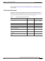
Site Environmental Requirements
Physical Characteristics 2-9
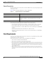
Rack Requirements
2-7
2-8
2-9
Router Environmental Requirements
2-10
Power Guidelines and Requirements
2-11
Network Cabling Specifications 2-11
Console and Auxiliary Port Considerations
Console Port Connections 2-12
Auxiliary Port Connections 2-13
Preparing for Network Connections 2-14
Ethernet Connections 2-14
2-12
Required Tools and Equipment for Installation and Maintenance
Installation Checklist
Creating a Site Log
CHAPTER
3
2-16
2-17
Installing and Connecting the Router
What You Need to Know
Before You Begin
2-14
3-1
3-3
3-3
Unpacking the Router
3-4
Installing the Router 3-4
Rack-Mounting the Chassis 3-5
Attaching Rack-Mount Brackets
3-5
Hardware Installation Guide for the Cisco 4451-X Integrated Services Router
iv
Contents
Mounting the Router in a Rack 3-7
Grounding the Chassis 3-9
Setting the Chassis on a Desktop 3-10
Chassis Grounding
3-11
Connecting Power 3-12
Connecting to AC Power
3-13
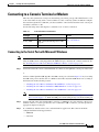
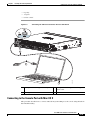
Connecting to a Console Terminal or Modem 3-14
Connecting to the Serial Port with Microsoft Windows
Connecting to the Console Port with Mac OS X 3-15
Connecting to the Console Port with Linux 3-16
3-14
Installing the Cisco Microsoft Windows USB Device Driver 3-16
Installing the Cisco Microsoft Windows XP USB Driver 3-17
Installing the Cisco Microsoft Windows 2000 USB Driver 3-17
Installing the Cisco Microsoft Windows Vista USB Driver 3-17
Uninstalling the Cisco Microsoft Windows USB Driver 3-18
Uninstalling the Cisco Microsoft Windows XP and 2000 USB Driver
Uninstalling the Cisco Microsoft Windows Vista USB Driver 3-19
Connecting to the Auxiliary Port
3-18
3-19
Connecting WAN, LAN, and Voice Interfaces 3-20
Ports and Cabling 3-22
Connection Procedures and Precautions 3-22
CHAPTER
4
Initial Configuration
4-1
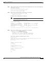
Performing the Initial Configuration on the Router 4-1
Using Cisco Setup Command Facility 4-1
Completing the Configuration 4-4
Using Cisco IOS-XE CLI—Manual Configuration 4-5
Configuring the Router Hostname 4-6
Configuring the Enable and Enable Secret Passwords 4-7
Configuring the Console Idle Privileged EXEC Timeout 4-8
Gigabit Ethernet Management Interface Overview 4-9
Default Gigabit Ethernet Configuration 4-10
Gigabit Ethernet Port Numbering 4-10
Configuring Gigabit Ethernet Interfaces 4-10
Configuration Examples 4-12
Specifying a Default Route or Gateway of Last Resort 4-12
Configuring IP Routing and IP Protocols 4-12
Default Routes 4-13
Default Network 4-13
Hardware Installation Guide for the Cisco 4451-X Integrated Services Router
v
Contents
Gateway of Last Resort 4-13
Configuration Examples 4-15
Configuring Virtual Terminal Lines for Remote Console Access
Configuration Examples 4-17
Configuring the Auxiliary Line 4-17
Verifying Network Connectivity 4-19
Saving Your Router Configuration 4-20
Saving Backup Copies of Configuration and System Image
Configuration Examples 4-21
Verifying the Initial Configuration
CHAPTER
5
4-20
4-23
ROM Monitor Overview and Basic Procedures
ROM Monitor Overview
4-16
5-1
5-1
Entering ROM Monitor Mode 5-2
Checking the Current ROMmon Version 5-2
Commonly Used ROM Monitor Commands 5-4
Displaying the Available ROM Monitor Commands
Examples 5-4
Changing the ROM Monitor Prompt 5-5
Displaying the Configuration Register Setting
5-4
5-5
Environment Variable Settings 5-5
Frequently Used Environmental Variables 5-6
Displaying Environment Variable Settings 5-6
Entering Environment Variable Settings 5-7
Saving Environment Variable Settings 5-7
Exiting ROM Monitor Mode 5-7
Configuration Example 5-8
Upgrading the ROMmon for a Router
Example of Upgrade 5-9
CHAPTER
6
5-9
Installing and Upgrading Internal Modules and FRUs
Safety Warnings
6-1
6-2
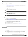
Accessing Internal Modules 6-4
Removing and Replacing the Chassis Cover
Removing the Cover 6-4
Replacing the Cover 6-4
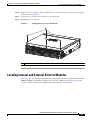
Locating Internal and External Slots for Modules
Overview of the SSD Carrier Card NIM (NIM-SSD)
6-4
6-5
6-6
Hardware Installation Guide for the Cisco 4451-X Integrated Services Router
vi
Contents
Overview 6-7
LEDs on the NIM-SSD 6-8
Solid State Drives (SSD) 6-10
Installing the SSD Drives into the NIM Carrier Card 6-12
Removing the SSD Drives from the NIM-SSD 6-13
Removing and Replacing the Cisco ISR 4451-X NIM-SSD Drives
Removing the NIM-SSD from the Router 6-16
Replacing the NIM-SSD on the Router 6-18
6-15
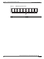
Installing and Removing DDR DIMMs 6-18
Locating and Orienting DIMM 6-18
Removing a DIMM 6-20
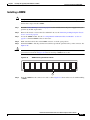
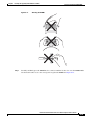
Installing a DIMM 6-21
Installing and Removing NIMs and SMs 6-23
Software Requirement for SMs 6-24
Locating an SM or NIM 6-24
Removing an SM or NIM 6-24
Installing an SM 6-24
Verifying SM Installation 6-25
Installing and Removing the PVDM4 6-25
Tools and Equipment Required During Installation 6-26
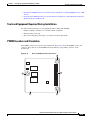
PVDM4 Location and Orientation 6-26
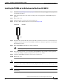
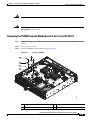
Installing the PVDM4 on the Motherboard of the Cisco ISR 4451-X 6-27
Removing the PVDM4 from the Motherboard of the Cisco ISR 4451-X 6-28
Installing the PVDM4 on the Cisco Fourth-Generation T1/E1 Voice and WAN NIM in the Cisco ISR
4451-X 6-29
Removing the PVDM4 from the Cisco Fourth-Generation T1/E1 Voice and WAN Network Interface
Module in the Cisco ISR 4451-X 6-30
Removing and Replacing the USB Flash Token Memory Stick
6-30
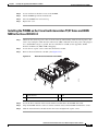
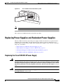
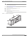
Replacing Power Supplies and Redundant Power Supplies 6-31
Replacing the Cisco ISR 4451-X Power Supply 6-31
Replacing the Power Supply on the Cisco ISR 4451-Xs 6-33
Inserting PoE Supply in an Ethernet Switch Network Module 6-33
Cisco ISR 4451-X Power and RPS Error Messages 6-34
Replacing a Fan Tray 6-34
Before Hot-Swapping a Fan Tray 6-34
Replacing the Cisco ISR 4451-X Fan Tray 6-34
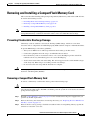
Removing and Installing a CompactFlash Memory Card
Preventing Electrostatic Discharge Damage 6-36
Removing a CompactFlash Memory Card 6-36
6-36
Hardware Installation Guide for the Cisco 4451-X Integrated Services Router
vii
Contents
Installing a CompactFlash Memory Card
6-37
Installing SFP Modules 6-38
Laser Safety Guidelines 6-40
Removing SFP Modules 6-40
Removing, Replacing, and Installing an Internal PoE Card
CHAPTER
7
Online Insertion and Removal (OIR) and Hot-Swapping
OIR Procedures 7-2
Removing a Module 7-2
Inserting a Data or Voice Module
Hot-Swapping Procedures
6-41
7-1
7-2
7-2
Hardware Installation Guide for the Cisco 4451-X Integrated Services Router
viii
Preface
This preface describes the objectives, audience, organization and conventions of this guide, and the
references that accompany this document set. The following sections are provided:
•
Objectives, page ix
•
Audience, page ix
•
Organization, page x
•
Conventions, page xi
•
Related Documentation, page xvii
•
Searching for Cisco Documents, page xviii
•
Obtaining Documentation and Submitting a Service Request, page xviii
Objectives
This guide explains how to install, connect, and perform initial configurations for the Cisco 4451-X
Integrated Services Router (ISR).
Note
For warranty, service, and support information, see the “Cisco Warranty Terms” section in the
Pointer Card for the Cisco 4451-X Integrated Services Router document that was shipped with
your router.
Audience
This guide is intended for Cisco equipment providers and service persons who are technically
knowledgeable and familiar with Cisco routers and Cisco IOS software and features. They would
understand how to install, configure, and maintain the router, and they should be familiar with electronic
circuitry and wiring practices, and have experience as an electronic or electromechanical technician.
This guide identifies certain procedures that should be performed only by trained and qualified
personnel.
Hardware Installation Guide for the Cisco 4451-X Integrated Services Router
OL-27644-01
ix
Organization
This guide includes the following chapters:
Chapter
Title
Description
1
Overview of the Cisco 4451-X
Integrated Services Router
Describes the router chassis views, information
for locating the serial number, PID1, and UDI2.
Also includes general hardware features, slot,
port, and interface information; and LED
indicators.
2
Preparing for Router Installation
Describes site requirements and the equipment
needed to install the router.
3
Installing and Connecting the Router Describes how to install and connect the router to
LAN, WAN, and Voice networks.
4
Initial Configuration
Describes how to power up the router and
perform the initial configuration.
5
ROM Monitor Overview and Basic
Procedures
Provides an overview of ROM Monitor concepts
and operations.
6
Installing and Upgrading Internal
Modules and FRUs
Describes how to install and upgrade internal
modules and field replaceable units3 on the
router.
7
Online Insertion and Removal (OIR) Describes how to remove and replace data and
and Hot-Swapping
modules using the online insertion and removal4
procedure.
1. PID = Product ID
2. UDI = Universal Device Identifier
3. FRU = Field Replaceable Unit
4. OIR = Online Insertion and Removal
Hardware Installation Guide for the Cisco 4451-X Integrated Services Router
x
OL-27644-01
Conventions
This document uses the following conventions:
Convention
Indication
bold font
Commands and keywords and user-entered text appear in bold font.
italic font
Document titles, new or emphasized terms, and arguments for which you supply
values are in italic font.
[ ]
Elements in square brackets are optional.
{x | y | z }
Required alternative keywords are grouped in braces and separated by
vertical bars.
[x|y|z]
Optional alternative keywords are grouped in brackets and separated by
vertical bars.
string
A nonquoted set of characters. Do not use quotation marks around the string or
the string will include the quotation marks.
courier
font
Terminal sessions and information the system displays appear in courier font.
< >
Nonprinting characters such as passwords are in angle brackets.
[ ]
Default responses to system prompts are in square brackets.
!, #
An exclamation point (!) or a pound sign (#) at the beginning of a line of code
indicates a comment line.
Note
Means reader take note.
Tip
Means the following information will help you solve a problem.
Caution
Timesaver
Means reader be careful. In this situation, you might perform an action that could result in equipment
damage or loss of data.
Means the described action saves time. You can save time by performing the action described in
the paragraph.
Hardware Installation Guide for the Cisco 4451-X Integrated Services Router
OL-27644-01
xi
Warning
IMPORTANT SAFETY INSTRUCTIONS
This warning symbol means danger. You are in a situation that could cause bodily injury. Before you
work on any equipment, be aware of the hazards involved with electrical circuitry and be familiar
with standard practices for preventing accidents. Use the statement number provided at the end of
each warning to locate its translation in the translated safety warnings that accompanied this
device. Statement 1071
SAVE THESE INSTRUCTIONS
Waarschuwing
BELANGRIJKE VEILIGHEIDSINSTRUCTIES
Dit waarschuwingssymbool betekent gevaar. U verkeert in een situatie die lichamelijk letsel kan
veroorzaken. Voordat u aan enige apparatuur gaat werken, dient u zich bewust te zijn van de bij
elektrische schakelingen betrokken risico's en dient u op de hoogte te zijn van de standaard
praktijken om ongelukken te voorkomen. Gebruik het nummer van de verklaring onderaan de
waarschuwing als u een vertaling van de waarschuwing die bij het apparaat wordt geleverd, wilt
raadplegen.
BEWAAR DEZE INSTRUCTIES
Varoitus
TÄRKEITÄ TURVALLISUUSOHJEITA
Tämä varoitusmerkki merkitsee vaaraa. Tilanne voi aiheuttaa ruumiillisia vammoja. Ennen kuin
käsittelet laitteistoa, huomioi sähköpiirien käsittelemiseen liittyvät riskit ja tutustu
onnettomuuksien yleisiin ehkäisytapoihin. Turvallisuusvaroitusten käännökset löytyvät laitteen
mukana toimitettujen käännettyjen turvallisuusvaroitusten joukosta varoitusten lopussa näkyvien
lausuntonumeroiden avulla.
SÄILYTÄ NÄMÄ OHJEET
Attention
IMPORTANTES INFORMATIONS DE SÉCURITÉ
Ce symbole d'avertissement indique un danger. Vous vous trouvez dans une situation pouvant
entraîner des blessures ou des dommages corporels. Avant de travailler sur un équipement, soyez
conscient des dangers liés aux circuits électriques et familiarisez-vous avec les procédures
couramment utilisées pour éviter les accidents. Pour prendre connaissance des traductions des
avertissements figurant dans les consignes de sécurité traduites qui accompagnent cet appareil,
référez-vous au numéro de l'instruction situé à la fin de chaque avertissement.
CONSERVEZ CES INFORMATIONS
Warnung
WICHTIGE SICHERHEITSHINWEISE
Dieses Warnsymbol bedeutet Gefahr. Sie befinden sich in einer Situation, die zu Verletzungen führen
kann. Machen Sie sich vor der Arbeit mit Geräten mit den Gefahren elektrischer Schaltungen und
den üblichen Verfahren zur Vorbeugung vor Unfällen vertraut. Suchen Sie mit der am Ende jeder
Warnung angegebenen Anweisungsnummer nach der jeweiligen Übersetzung in den übersetzten
Sicherheitshinweisen, die zusammen mit diesem Gerät ausgeliefert wurden.
BEWAHREN SIE DIESE HINWEISE GUT AUF.
Hardware Installation Guide for the Cisco 4451-X Integrated Services Router
xii
OL-27644-01
Avvertenza
IMPORTANTI ISTRUZIONI SULLA SICUREZZA
Questo simbolo di avvertenza indica un pericolo. La situazione potrebbe causare infortuni alle
persone. Prima di intervenire su qualsiasi apparecchiatura, occorre essere al corrente dei pericoli
relativi ai circuiti elettrici e conoscere le procedure standard per la prevenzione di incidenti.
Utilizzare il numero di istruzione presente alla fine di ciascuna avvertenza per individuare le
traduzioni delle avvertenze riportate in questo documento.
CONSERVARE QUESTE ISTRUZIONI
Advarsel
VIKTIGE SIKKERHETSINSTRUKSJONER
Dette advarselssymbolet betyr fare. Du er i en situasjon som kan føre til skade på person. Før du
begynner å arbeide med noe av utstyret, må du være oppmerksom på farene forbundet med
elektriske kretser, og kjenne til standardprosedyrer for å forhindre ulykker. Bruk nummeret i slutten
av hver advarsel for å finne oversettelsen i de oversatte sikkerhetsadvarslene som fulgte med denne
enheten.
TA VARE PÅ DISSE INSTRUKSJONENE
Aviso
INSTRUÇÕES IMPORTANTES DE SEGURANÇA
Este símbolo de aviso significa perigo. Você está em uma situação que poderá ser causadora de
lesões corporais. Antes de iniciar a utilização de qualquer equipamento, tenha conhecimento dos
perigos envolvidos no manuseio de circuitos elétricos e familiarize-se com as práticas habituais de
prevenção de acidentes. Utilize o número da instrução fornecido ao final de cada aviso para
localizar sua tradução nos avisos de segurança traduzidos que acompanham este dispositivo.
GUARDE ESTAS INSTRUÇÕES
¡Advertencia!
INSTRUCCIONES IMPORTANTES DE SEGURIDAD
Este símbolo de aviso indica peligro. Existe riesgo para su integridad física. Antes de manipular
cualquier equipo, considere los riesgos de la corriente eléctrica y familiarícese con los
procedimientos estándar de prevención de accidentes. Al final de cada advertencia encontrará el
número que le ayudará a encontrar el texto traducido en el apartado de traducciones que acompaña
a este dispositivo.
GUARDE ESTAS INSTRUCCIONES
Varning!
VIKTIGA SÄKERHETSANVISNINGAR
Denna varningssignal signalerar fara. Du befinner dig i en situation som kan leda till personskada.
Innan du utför arbete på någon utrustning måste du vara medveten om farorna med elkretsar och
känna till vanliga förfaranden för att förebygga olyckor. Använd det nummer som finns i slutet av
varje varning för att hitta dess översättning i de översatta säkerhetsvarningar som medföljer denna
anordning.
SPARA DESSA ANVISNINGAR
Hardware Installation Guide for the Cisco 4451-X Integrated Services Router
OL-27644-01
xiii
Hardware Installation Guide for the Cisco 4451-X Integrated Services Router
xiv
OL-27644-01
Aviso
INSTRUÇÕES IMPORTANTES DE SEGURANÇA
Este símbolo de aviso significa perigo. Você se encontra em uma situação em que há risco de lesões
corporais. Antes de trabalhar com qualquer equipamento, esteja ciente dos riscos que envolvem os
circuitos elétricos e familiarize-se com as práticas padrão de prevenção de acidentes. Use o
número da declaração fornecido ao final de cada aviso para localizar sua tradução nos avisos de
segurança traduzidos que acompanham o dispositivo.
GUARDE ESTAS INSTRUÇÕES
Advarsel
VIGTIGE SIKKERHEDSANVISNINGER
Dette advarselssymbol betyder fare. Du befinder dig i en situation med risiko for
legemesbeskadigelse. Før du begynder arbejde på udstyr, skal du være opmærksom på de
involverede risici, der er ved elektriske kredsløb, og du skal sætte dig ind i standardprocedurer til
undgåelse af ulykker. Brug erklæringsnummeret efter hver advarsel for at finde oversættelsen i de
oversatte advarsler, der fulgte med denne enhed.
GEM DISSE ANVISNINGER
Hardware Installation Guide for the Cisco 4451-X Integrated Services Router
OL-27644-01
xv
Hardware Installation Guide for the Cisco 4451-X Integrated Services Router
xvi
OL-27644-01
Warning
When installing the product, please use the provided or designated connection cables/power
cables/AC adaptors. Using any other cables/adaptors could cause a malfunction or a fire. Electrical
Appliance and Material Safety Law prohibits the use of UL-certified cables (that have the “UL” shown
on the code) for any other electrical devices than products designated by CISCO. The use of cables
that are certified by Electrical Appliance and Material Safety Law (that have “PSE” shown on the
code) is not limited to CISCO-designated products. Statement 371.
Warning
There is the danger of explosion if the battery is replaced incorrectly. Replace the battery only with
the same or equivalent type recommended by the manufacturer. Dispose of used batteries according
to the manufacturer’s instructions. Statement 1015
Warning
Do not use this product near water; for example, near a bath tub, wash bowl, kitchen sink or laundry
tub, in a wet basement, or near a swimming pool. Statement 1035
Warning
Never install telephone jacks in wet locations unless the jack is specifically designed for
wet locations. Statement 1036
Warning
Never touch uninsulated telephone wires or terminals unless the telephone line has been
disconnected at the network interface. Statement 1037
Related Documentation
For a list of all related release and supported module documentation, see the Documentation Roadmap
for the Cisco 4451-X Integrated Services Routers at the following URL:
http://www.cisco.com/en/US/docs/routers/access/4400/roadmap/isr4400roadmap.html
Hardware Installation Guide for the Cisco 4451-X Integrated Services Router
OL-27644-01
xvii
Searching for Cisco Documents
To search an HTML document using a web browser, press Ctrl-F (Windows) or Cmd-F (Apple). In most
browsers, the option to search whole words only, invoke case sensitivity, or search forward and backward
is also available.
To search a PDF document in Adobe Reader, use the basic Find toolbar (Ctrl-F) or the Full Reader
Search window (Shift-Ctrl-F). Use the Find toolbar to find words or phrases within a specific document.
Use the Full Reader Search window to search multiple PDF files simultaneously and to change case
sensitivity and other options. The Adobe Reader online help has more information about how to search
PDF documents.
Obtaining Documentation and Submitting a Service Request
For information on obtaining documentation, submitting a service request, and gathering additional
information, see What’s New in Cisco Product Documentation at:
http://www.cisco.com/en/US/docs/general/whatsnew/whatsnew.html.
Subscribe to What’s New in Cisco Product Documentation, which lists all new and revised Cisco technical
documentation, as an RSS feed and deliver content directly to your desktop using a reader application. The
RSS feeds are a free service
Hardware Installation Guide for the Cisco 4451-X Integrated Services Router
xviii
OL-27644-01
CH A P T E R
1
Overview of the Cisco 4451-X Integrated Services
Router
About the Cisco ISR 4451-X
The Cisco 4451-X Integrated Services Router (ISR) is a modular router with LAN and WAN
connectivity and supports several interface modules, including Cisco Service Modules (SMs), or
Enhanced Service Modules (SM-X), and Network Interface Modules (NIMs). The router has slots that
support the interface modules and modular Solid State Drives (SSDs).
The Cisco ISR 4451-Xs target the following applications:
•
Enterprise applications—Intended as the mid-size aggregation and gateway router typically residing
in a regional or large branch office:
– WAN aggregation at Cisco Enterprise core
– Internet gateway
– Branch or regional office aggregation
– Remote access aggregation
•
Service provider applications—Intended for high-end Enterprise Branch environments.:
– High-end customer premises equipment (CPE) for business-quality Internet access
– Service provider leased line aggregation
– Provider edge (PE) and high-end customer edge (CE) for Layer 2 VPN or Layer 3 VPN services
– Broadband aggregation—PPPoE/PPPoA aggregation and Service Selection Gateway (SSG)
– Low-end Ethernet aggregation
The Cisco ISR 4451-Xs provide the following capabilities:
•
Two single-wide SM slots that may be combined into one double wide SM slot.
•
Three single-wide NIM slots that may combined into one double wide (NIM1 and NIM2) and one
single wide NIM slot (NIM3). The slots can also support a modular or optional SSD.
•
NIM3 slot also functions as a special hard drive carrier slot.
•
1 10/100/1000 RJ-45 Ethernet port for system managements (labeled "GE 0" with “MGMT” on the
left of the connector)
•
2 USB 2 Type A host ports
•
1 USB mini-TypeB Console (placed next to the RJ45 Console port)
Hardware Installation Guide for the Cisco 4451-X Integrated Services Router
OL-27644-01
1-1
Chapter 1
Overview of the Cisco 4451-X Integrated Services Router
Safety Warnings
•
1 RJ45 Console
•
1 RJ45 AUX port with full modem control signals
•
4 10/100/1000 RJ-45 Ethernet ports (labeled GE 0/0/0, 0/0/1, 0/0/2, and 0/0/3)
•
4 100/1000 SFP Ethernet ports (labeled SFP 0/0/0, 0/0/1, 0/0/2, and 0/0/3)
•
LEDs for Ethernet and console status
•
LEDs for SATA hard disk drive activity and status (available on certain models)
•
Two DDR3 240 pin Control Plane DIMM slots which can be replaced
•
One DDR3 240 pin Data Plane DIMM slot which can be replaced
•
One compact flash slot, which is serviceable when the fan tray is removed
•
One 30W PoE daughter card for two of the front Gigabit Ethernet ports which can be replaced
(labeled GE 0/0/0 and 0/0/1)
•
One Packet Voice Digital Signal Processor Module (PVDM4) providing IP Voice and video
capability
•
Environment monitoring
•
Field replaceable fan tray
•
Dual redundant power supply units (PSUs) and PoE PSU.
This chapter contains the following sections:
•
Safety Warnings, page 1-2
•
Chassis Views, page 1-3
•
Locating the Serial Number, PID, VID and CLEI, page 1-7
•
Hardware Features, page 1-9
•
About Slots and Interfaces, page 1-17
•
Specifications, page 1-20
•
Periodic Inspection and Cleaning, page 1-25
Safety Warnings
Warning
IMPORTANT SAFETY INSTRUCTIONS
This warning symbol means danger. You are in a situation that could cause bodily injury. Before you
work on any equipment, be aware of the hazards involved with electrical circuitry and be familiar
with standard practices for preventing accidents. Use the statement number provided at the end of
each warning to locate its translation in the translated safety warnings that accompanied this device.
Statement 1071
SAVE THESE INSTRUCTIONS
Hardware Installation Guide for the Cisco 4451-X Integrated Services Router
OL-27644-01
1-2
Chapter 1
Overview of the Cisco 4451-X Integrated Services Router
Chassis Views
Warning
Ultimate disposal of this product should be handled according to all national laws and regulations.
Statement 1040
Warning
Only trained and qualified personnel should be allowed to install, replace, or service this equipment.
Statement 1030
Safety Warnings for Finland, Norway and Sweden
Warning statement 1017 applies to the countries of Finland, Norway, and Sweden.
Warning
This unit is intended for installation in restricted access areas. A restricted access area can be
accessed only through the use of a special tool, lock and key, or other means of security.
Statement 1017
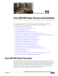
Chassis Views
This section contains views of the front and back panels of the Cisco ISR 4451-Xs, showing locations
of the power and signal interfaces, module slots, status indicators, and chassis identification labels.
Note
The Cisco ISR 4451-Xs support the following slot types:
- Network Interface Modules (NIMs)
- Service modules (SMs, like SM-X-1T3/E3)
- Integrated Services Card (ISC slots for PVDM4s)
- E-Series Server Modules
- Solid State Drives (SSDs).
Hardware Installation Guide for the Cisco 4451-X Integrated Services Router
OL-27644-01
1-3
Chapter 1
Overview of the Cisco 4451-X Integrated Services Router
Chassis Views
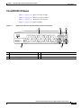
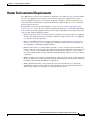
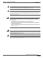
Cisco ISR 4451-X Chassis
Figure 1-1 on page 1-4— Bezel view with one PSU
Figure 1-2 on page 1-5— Bezel view with two PSUs
Figure 1-3 on page 1-5— Back panel slots and ports
Figure 1-4 on page 1-6—Bezel side LEDs
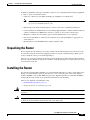
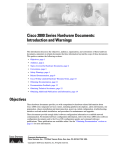
Figure 1-1
Bezel View of the Cisco ISR 4451-X with one Power Supply Unit
1
2
3
Cisco 4400 Series
PSU1
PSU2
INT
POE1
POE2
BOOST
FLASH
TEMP
PWR
VM
FAN
STAT
285694
POE
5
4
1
Router fan tray
2
LEDs
3
Router power On/Off switch
4
Power supply unit (PSU)
5
Optional power supply unit
Hardware Installation Guide for the Cisco 4451-X Integrated Services Router
OL-27644-01
1-4
Chapter 1
Overview of the Cisco 4451-X Integrated Services Router
Chassis Views
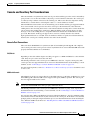
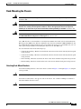
Figure 1-2
Bezel side of the Cisco ISR 4451-X with two PSUs
1
2
3
Cisco 4400 Series
PSU1
PSU2
INT
POE1
POE2
BOOST
FLASH
TEMP
PWR
VM
FAN
STAT
285695
POE
5
4
1
Router fan tray
2
LEDs
3
Router power On/Off switch
4
AC power supply unit (P1)
5
AC power supply unit (P0)
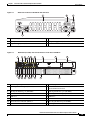
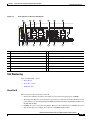
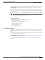
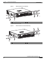
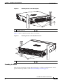
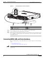
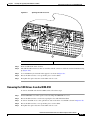
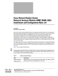
Back Panel (I/O Side) Slots and Connectors on the Cisco ISR 4451-X
1
2
3
5
6
4
8
9
10
11
7
1
2
23
22
21
20
18
19
285698
Figure 1-3
15
17 16
14
13
12
1
GE 0 management port
2
Auxiliary port
3
RJ45 Gigabit Ethernet port (GE 0/0/0)
4
LEDs for the GE 0/0/0 interface (See Table 1-1 for
detailed LED information)
5
SFP Gigabit Ethernet port (GE 0/0/0)
6
SFP Gigabit Ethernet port (GE 0/0/2)
7
LEDs for the GE 0/0/2 interface
8
RJ45 Gigabit Ethernet port (GE 0/0/2)
9
NIM slot 1
10 NIM slot 2
11 NIM slot 3 (Optional Modular SSD Slot)
12 Enhanced Service Module (SM-X) 2
13 Enhanced Service Module (SM-X) 1
14 RJ45 Gigabit Ethernet port GE 0/0/3
15 LEDs for the GE 0/0/3 interface
16 SFP Gigabit Ethernet GE 0/0/3
Hardware Installation Guide for the Cisco 4451-X Integrated Services Router
OL-27644-01
1-5
Chapter 1
Overview of the Cisco 4451-X Integrated Services Router
Chassis Views
17 SFP Gigabit Ethernet GE 0/0/1
18 LEDs for the GE 0/0/1 interface
19 RJ45 Gigabit Ethernet port GE 0/0/1
20 Serial Console Port
21 Console port USB 0 and USB 1
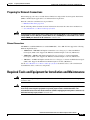
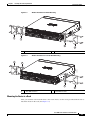
Figure 1-4
Bezel Side LEDS of the Single PSU Cisco ISR 4451-X Model
1
2
3
PSU0
PSU1
INT
4
5
FLASH TEMP
6
PWR
POE
POE0
POE1
BOOST
VM
FAN
STAT
12
11
10
9
8
7
Cisco 4400 Series
PSU1
PSU0
PSU2
PSU1
POE1
POE0
POE2
BOOST
POE1 BOOST
INT
INT
FLASH
TEMP
FLASH TEMP
PWR
PWR
POE
POE
FAN
FAN
STAT
285696
VM
VM
1
PSU0: Power supply unit 1
2
PSU1: Power supply unit 2
3
GE POE: Internal PoE daughter card status
4
FLASH: Compact flash status
5
TEMP: Temperature status
6
PWR: Power
7
STAT: System status
8
FAN: Fan status
9
ISC: Integrated Services Card status
10 POE BOOST: Power over Ethernet boost mode
11 POE 1: Power over Ethernet 2 status
12 POE 0: Power over Ethernet 1 status
Hardware Installation Guide for the Cisco 4451-X Integrated Services Router
OL-27644-01
1-6
Chapter 1
Overview of the Cisco 4451-X Integrated Services Router
Locating the Serial Number, PID, VID and CLEI
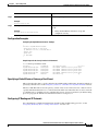
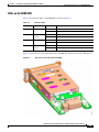
Platform Summary
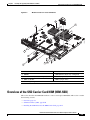
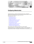
Figure 1-5 shows an internal view of the Cisco ISR 4451-X with all the parts and module location.
Figure 1-5
Platform Summary of the Cisco ISR 4451-X
2
3
285699
1
9
8
6
5
7
4
1.
ISC slot
2.
CPU
3.
DIMM
4.
Modular HDD Slot (Factory-configured)
5.
Modular HDD slot (Factory-configured)
6.
NIM 2 (single-wide)
7.
NIM slot divider
8.
NIM 1 (single-wide)
Locating the Serial Number, PID, VID and CLEI
Software License
To obtain a software license, you need a product authorization key (PAK) and the unique device
identifier (UDI) of the device where the license will be installed.
The serial number (SN), product ID (PID), version ID (VID), and Common Language Equipment
Identifier (CLEI) are printed on a label on the back of the router or on a label tray located on the router
chassis or motherboard. The UDI can be viewed using the show license udi command in privileged Exec
Hardware Installation Guide for the Cisco 4451-X Integrated Services Router
OL-27644-01
1-7
Chapter 1
Overview of the Cisco 4451-X Integrated Services Router
Locating the Serial Number, PID, VID and CLEI
mode in Cisco Internet Operating System (IOS) software. For additional information on the UDI or how
to obtain a PAK, see the Cisco Software Activation on Integrated Services Routers document on
Cisco.com.
The UDI has two main components:
•
Product ID (PID)
•
Serial number (SN)
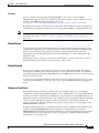
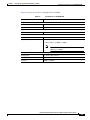
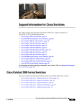
Labels on Cisco ISR 4451-X
Figure 1-6 shows the location of the labels on the Cisco ISR 4451-Xs.
Figure 1-6
Label Location on the Cisco ISR 4451-X
2
1
3
302982
4
Label
Description
1
Product ID
2
Serial Number
3
PID/VID
4
CLEI
For Additional Help Locating Labels on the Router
Use the Cisco Product Identification (CPI) tool to find labels on the router. It provides detailed
illustrations and descriptions of where the labels are located on Cisco products. It includes the following
features:
•
A search option that allows browsing for models by using a tree-structured product hierarchy
•
A search field on the final results page that makes it easier to look up multiple products
•
End-of-sale products clearly identified in results lists
The tool streamlines the process of locating serial number labels and identifying products. Serial number
information expedites the entitlement process and is important for access to support services.
Hardware Installation Guide for the Cisco 4451-X Integrated Services Router
OL-27644-01
1-8
Chapter 1
Overview of the Cisco 4451-X Integrated Services Router
Hardware Features
The Cisco Product Identification tool can be accessed at the following URL:
http://tools.cisco.com/Support/CPI/index.do
Hardware Features
This section describes the hardware features in the Cisco ISR 4451-X.
•
Built-in Interface Ports, page 1-9
•
LED Indicators, page 1-11
•
Removable and Interchangeable Modules and Cards, page 1-13
•
Fans, Ventilation, and Airflow, page 1-17
•
About Slots and Interfaces, page 1-17
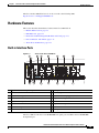
Built-in Interface Ports
Figure 1-7
1
Ports on the Cisco ISR 4451-X
4
5
3
6
7
8
2
L
16
15
14
13
12
11
10
9
1
Gigabit Ethernet management port
2
USB port 0
3
USB console
4
Auxiliary port
5
Gigabit Ethernet port 0
6
Small-form-factor pluggable (SFP) 0
7
SFP 2
8
Gigabit Ethernet port 2
9
Gigabit Ethernet port 3
10 SFP 3
11 SFP 1
12 Gigabit Ethernet port 1
13 Serial Console port
14 HDD LEDs
15 HDD LEDs
16 USB port 1
285701
L
The Cisco ISR 4451-Xs have four 10/100/1000 front panel ports and SFPs and one 10/100/1000
management port.
Hardware Installation Guide for the Cisco 4451-X Integrated Services Router
OL-27644-01
1-9
Chapter 1
Overview of the Cisco 4451-X Integrated Services Router
Hardware Features
Front Panel Ethernet Ports
There are 4 front panel Ethernet ports. Each port independently supports dual-media types, RJ45 copper
or SFPs.
Dual Mode GE/SFP Ports
There are Dual Mode ports available on the Cisco ISR 4451-X that can function as GE or SFP ports.
GE Ports
The GE RJ-45 copper interface ports support 10BASE-T, 100BASE-TX, and 1000BASE-T.
SFP Ports
The small-form-factor pluggable (SFP) ports support, but are not restricted to 1000BASE-LX/LH,
1000BASE-SX, 1000BASE-ZX, and Coarse Wavelength-Division Multiplexing (CWDM-8) modules, as
well as 100Mbs SFP modules.
The SFP port shares the same physical port as an RJ-45 GE port with the same number. It can only be
used for one or the other function at one time. The SFP port supports auto-media-detection, auto-failover
and remote fault indication (RFI), as described in the IEEE 802.3ah specification.
Use the media-type {rj45{auto-failover}} | {sfp{auto-failover}} command to enable the
auto-media-detection and auto-failover features. Use the Command Lookup Tool for details about this
command.
The SFP port can be configured for the following behaviors:
•
Always use the RJ-45 port.
•
Always use the SFP port.
•
Always use the RJ-45 port but fail over to the SFP port if the RJ-45 port fails. This is the default
configuration.
•
Always use the SFP port but fail over to the RJ-45 port if the SFP port fails.
USB Serial Console Port
The Mini-USB type B serial port can be used as an alternative to the RJ45 console port. For Windows
operating systems older than Windows 7, you must install a Windows USB device driver before using
the USB console port.
Front Panel PoE+ Ports
Two of the four front panel ethernet ports are PoE+ (802.3at) compliant ports. These are ports GE 0/0/0
and GE 0/0/1.
System PoE power supplies do not provide power to the front panel ports.
Note
The PoE card is always required to provide PoE power to these ports, regardless of what other power
supplies are present in the system. An internal PoE module needs to be ordered separately for this
functionality.
Hardware Installation Guide for the Cisco 4451-X Integrated Services Router
OL-27644-01
1-10
Chapter 1
Overview of the Cisco 4451-X Integrated Services Router
Hardware Features
Internal PoE card
The internal PoE daughter card provides a total of 30.8 Watts of power across the 2 ports.
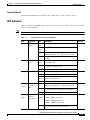
LED Indicators
Table 1-1 summarizes the LED indicators that are located in the router bezel or chassis, but not on the
interface cards and modules.
Note
For module LEDs, please refer to the respective module installation guides for each module.
Table 1-1
LED Indicators on the Cisco ISR 4451-X
LED
Represents
Color
Description
Location
STAT
System
Status
Solid
green
Normal System Operation.
Bezel side
Blinking BIOS/Rommon is in the process of booting.
amber
TEMP
FAN
Temperature
Status
Fan Status
Amber
BIOS/Rommon has completed booting and system
at Rommon prompt or booting platform software.
Off
System is not out of reset or BIOS image not
loadable.
Solid
green
All temperature sensors in the system are within
acceptable range.
Amber
One or more temperature sensors in the system are
outside the acceptable range.
Off
Temperature is not being monitored.
Green
All fans are operating.
Amber
One fan has stopped working.
Bezel side
Bezel side
Blinking Two or more fans have stopped working, or the fan
Amber
tray has been removed.
Off
L
(left)
Ethernet
Green
ports 0 and 1
Link
Amber
Off
S
(left)
Fans are not being monitored.
Ethernet cable present and link established with
other side or PoE power is enabled for this port.
I/O side
Yellow: PoE power for this connector is faulty and
link is down. (Only for Ethernet port 0 and 1.)
No link.
Speed of
Green
Blink frequency indicates port speed:
Ethernet
Blinking 1 blink - 10Mbps link speed
ports 0 and 1
2 blinks - 100Mbps link speed
I/O side
3 blinks - 1000Mbps link speed
Off
No link or a non-Ethernet 802.3af/t capable device
plugged in and powered over the PoE.
Hardware Installation Guide for the Cisco 4451-X Integrated Services Router
OL-27644-01
1-11
Chapter 1
Overview of the Cisco 4451-X Integrated Services Router
Hardware Features
Table 1-1
LED Indicators on the Cisco ISR 4451-X (continued)
LED
Represents
L
Green
Ethernet
ports 2 and 3
and
Off
Management
Ethernet
Link
(right)
S
(right)
SFP EN
SFP S
SER
CON
(right)
USB
CON
Color
Green
Ethernet
ports 2, and 3
and
Management
Ethernet
Speed
Off
Port 0, 1, 2, Green
and 3 Enable Amber
Description
Location
Ethernet cable present and link established with
other side.
I/O side
No link.
Blinking: blink frequency indicates port speed:
1 blink - 10Mbps link speed
2 blinks - 100Mbps link speed
3 blinks - 1000Mbps link speed
No link
Indicates SFP module detected and recognized.
Off
Not present.
Status of
Ports 0, 1, 2,
and 3
Green
tbd
Off
Not present.
Serial
Console
Active
Green
Indicates that the active console port is RJ-45.
FLASH
Compact
Flash Status
I/O side
Amber
Note
USB Console Green
Active
ISC Slot
Status
I/O side
Initialized with error.
I/O side
When this LED is on, the USB CON LED
will be off.
Green indicates that the active console port is USB. I/O side
Note
(left)
ISC
I/O side
When this LED is on, the SER CON LED
will be off.
Green
PVDM4 present and enabled.
Amber
Initialized with error.
Off
Not present.
Green
Present and inactive.
Bezel side
Bezel side
Blinking Compact flash present and currently being
Green
accessed.
Note
PSU
Power
Supply Unit
(P0 and P1)
Status
Do not remove the Compact Flash when this
LED is blinking.
Off
Not present.
Green
PSU on and providing power.
Amber
PSU is on but with errors or in a failure condition.
Off
Power supply turned off.
Bezel side
Hardware Installation Guide for the Cisco 4451-X Integrated Services Router
OL-27644-01
1-12
Chapter 1
Overview of the Cisco 4451-X Integrated Services Router
Hardware Features
Table 1-1
LED
LED Indicators on the Cisco ISR 4451-X (continued)
Represents
Color
Description
Location
POE PSU Power Over
Ethernet
(not
supported Power
in Cisco Supply Unit
1 and 2
IOS XE
Status
3.8)
Green
PSU is on and providing power.
Bezel side
Amber
PSU is on but with errors or in a failure condition.
Off
PSU is off.
POE
Boost
Green
Two PoE Power Supplies are installed and operating Bezel side
in boost mode.
Off
This can mean one of the following:
(not
supported
in Cisco
IOS XE
3.8)
GE POE
PWR
Power Over
Ethernet
Boost Mode
•
No PoE PSU installed
•
One PoE PSU installed
•
Two PoE PSUs installed and operating in
redundant mode.
Internal POE Green
Daughter
Amber
Card Status
Off
PSU installed and providing power
System
Power
Green
System power is on and functioning correctly.
Green
blinking
System power is in the process of shutting down.
Amber
System power is up, but low level initialization
failed.
Bezel side
PSU installed but in a failure condition.
PSU is off.
Bezel side
Amber
System power is up, but the system failed to come
blinking: out of reset.
AC OK
AC power
status
Off
System power is off.
Green
AC power is on.
Off
AC power is off.
On each
power
supply
unit
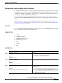
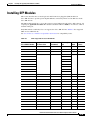
Removable and Interchangeable Modules and Cards
Table 1-2 on page 1-15 summarizes the type of removable modules and cards that can be installed in the
router to provide specific capabilities. Service Modules (SMs), Network Interface Modules (NIMs) and
E-Series Server Modules, fit into external slots and can be removed or replaced without opening the
chassis.
External Slots
•
Network Interface Modules, page 1-15
•
Cisco UCS E-Series Server Modules, page 1-15
•
Solid State Drives, page 1-15
Hardware Installation Guide for the Cisco 4451-X Integrated Services Router
OL-27644-01
1-13
Chapter 1
Overview of the Cisco 4451-X Integrated Services Router
Hardware Features
Internal Slots
•
Packet Voice Digital Signal Processor Modules, page 1-16
•
Memory, page 1-16
•
Compact Flash, page 1-15
Because of physical differences with the new slots, legacy network modules and legacy Service Modules
require an adapter for installation.
Warning
Only trained and qualified personnel should be allowed to install, replace, or service this equipment.
Statement 1030
Warning
This equipment must be installed and maintained by service personnel as defined by AS/NZS 3260.
Incorrectly connecting this equipment to a general-purpose outlet could be hazardous. The
telecommunications lines must be disconnected 1) before unplugging the main power connector or 2)
while the housing is open, or both. Statement 1043
See the Overview of Cisco Network Modules and Service Modules for Cisco Access Routers
document for general information and single- and double-wide slot numbering.
See the Installing Cisco Network Modules in Cisco Access Routers document for instructions that
describe how to install SMs in the router.
See the Overview of Cisco Interface Cards for Cisco Access Routers for general interface card
information.
See the Installing Cisco Interface Cards in Cisco Access Routers document, for instructions that
describe how to install legacy interface cards in the router.
Note
See the router product page at Cisco.com for a list of supported network modules and interface cards for
Cisco ISR 4451-Xs.
Hardware Installation Guide for the Cisco 4451-X Integrated Services Router
OL-27644-01
1-14
Chapter 1
Overview of the Cisco 4451-X Integrated Services Router
Hardware Features
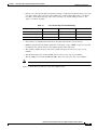
Table 1-2 shows the number of internal and external slots on Cisco ISR 4451-Xs. It also shows the
number of EHWICs and SMs that are supported in the router slots at any time.
Note
Table 1-2 is valid for Cisco IOS XE release 3.9.
T
Table 1-2
Cisco ISR 4451-X Slots and Module Configurations
Modules and Cards
Router
Cisco ISR
4451-X
Solid State Drive (SSD) Service Module (SM-X)
Network Interface Module (NIM)
E-Series Module (UCS)
1 single-wide
3 single-wide
or
1 double-wide + 1 single-wide
2 single-wide
or
1 double-wide
2 single-wide
or
1 double-wide
Network Interface Modules
To install the Cisco SM-X-1T3/E3 service modules on the router chassis, see the Installing Cisco
Network Modules in Cisco Access Routers guide for installation instructions at the following URL:
http://www.cisco.com/en/US/docs/routers/access/interfaces/nm/hardware/installation/guide/InstNetM.
html.
Cisco UCS E-Series Server Modules
The Cisco UCS E-Series Servers (E-Series Servers) are the next generation of Cisco UCS Express
servers. E-Series Servers are a family of size, weight, and power efficient blade servers that are housed
within the Generation 2 Cisco Integrated Services Routers (ISR G2) and the Cisco 4451-X Integrated
Services Router. These servers provide a general purpose compute platform for branch-office
applications deployed either as bare-metal on operating systems, such as Microsoft Windows or Linux;
or as virtual machines on hypervisors, such as VMware vSphere Hypervisor™, Microsoft Hyper-V, or
Citrix XenServer.
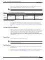
Compact Flash
The Cisco ISR 4451-Xs use a USB to Compact Flash.
Note
Do not run the router without a Compact Flash card installed. Cisco IOS-XE will not come up without
a compact flash card in the router.
Solid State Drives
The NIM slot 3 in the Cisco ISR 4451-X supports a field-replaceable solid state drive module with a
dual-SSD SATA slot.
The SSD slot is always powered up. The SSDs are hot-swappable as part of normal operation. See the
“Overview of the SSD Carrier Card NIM (NIM-SSD), page 6-6” section for more information.
Hardware Installation Guide for the Cisco 4451-X Integrated Services Router
OL-27644-01
1-15
Chapter 1
Overview of the Cisco 4451-X Integrated Services Router
Hardware Features
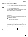
Packet Voice Digital Signal Processor Modules
The Packet Voice Digital Signal Processor Modules (PVDM4s) add additional voice capabilities to the
Cisco ISR 4451-Xs. The PVDM4 is installed inside the chassis of the router. See the “Installing the
PVDM4 on the Motherboard of the Cisco ISR 4451-X” section on page 6-27 for installation instructions.
Memory
Cisco ISR 4451-X routers contain the following types of memory:
Control and data plane DIMMs—Stores the running configuration and routing tables and is used for
packet buffering by the network interfaces. Cisco IOS XE software executes from memory.
Supported module types are Dual In-Line Memory Modules (DIMMs).
•
The DIMMs are interchangeable although the same sizes are not supported in all locations. The
single data plane DIMM must have a 2GB DIMM which is exactly like one of the two DIMMs
used for the control plane with 4GB default memory. The control plane uses two DIMMs and
they must be exactly the same type and density.
Note
•
Boot/NVRAM—Stores the bootstrap program (ROM monitor), the configuration register, and the
startup configuration.
•
Flash memory—Internal bootflash memory. Stores the operating system software image. Each
model supports 1 internal Compact Flash 8GB, 15GB or 32 GB memory card. The compact flash is
located behind the fan tray on the router chassis.
Note
You must use Cisco-qualified CompactFlash cards. Use of any other cards during normal
network operation can affect system performance.
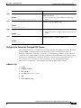
Power Supplies
Cisco ISR 4451-Xs support a variety of power supply configurations. All power supplies are
field-replaceable and externally accessible.
If configured with dual power supplies or a PoE adaptor, the power supplies are hot-swappable. There is
an option for a second power supply unit.
Configurations include AC, internal PoE, and PoE boost. Table 1-3 summarizes the power options.
Table 1-3
Router Model
Cisco ISR 4451
-X
Cisco ISR 4451-X Field Replaceable Unit Power Options
Hot Swap1
AC
X
X
Additional AC Power
Internal PoE
X
Internal PoE Boost
X
1. Must have PoE boost installed.
Hardware Installation Guide for the Cisco 4451-X Integrated Services Router
OL-27644-01
1-16
Chapter 1
Overview of the Cisco 4451-X Integrated Services Router
About Slots and Interfaces
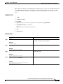
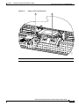
Fans, Ventilation, and Airflow
Chassis Ventilation
An internal fan tray consisting of 4 fans provides chassis cooling. An onboard temperature sensor
controls the fan speed. The fans are always on when the router is powered on. Under most conditions,
the fans operate at the slowest speed to conserve power and reduce fan noise. The fans operate at the
higher speeds when necessary under conditions of higher ambient temperature. To replace a fan tray, see
the “Replacing a Fan Tray” section on page 6-34.
•
Figure 1-8 shows the Cisco ISR 4451-X airflow.
Cisco ISR 4451-X Airflow)
303009
Figure 1-8
About Slots and Interfaces
This section covers the following topics:
•
About Slot, Subslot (Bay), and Port Numbering, page 1-17
•
Slot Numbering, page 1-19
•
Subslot/Bay Numbering, page 1-20
•
Gigabit Ethernet Management, page 1-20
•
About Fixed Interfaces, page 1-20
About Slot, Subslot (Bay), and Port Numbering
The Cisco ISR 4451-X supports two types of interface modules: Enhanced Service Modules (SMs) and
Network Modules (NIMs).
Hardware Installation Guide for the Cisco 4451-X Integrated Services Router
OL-27644-01
1-17
Chapter 1
Overview of the Cisco 4451-X Integrated Services Router
About Slots and Interfaces
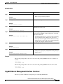
•
In most cases, the router designates its interfaces using a 3-tuple notation that lists the slot, bay, and
port. The 3-tuple value is zero based. An example of a 3-tuple is 0/1/2. This refers to slot 0, the
second bay in slot 0 (the first bay is 0 so the second bay is 1), and the third port in bay 1. See
Table 1-4 for more examples.
Table 1-4
Slot, Subslot (Bay) and Port Numbering
3-Tuple Example
Slot
Bay
Port
0/1/2
0
2nd
3rd
0/0/1
0
1st
2nd
1/1/1
1
2nd
2nd
•
Slots and bays are numbered from the left to the right, and from the top to the bottom.
•
NIMs are designated by the number of the first slot that they occupy. A NIM occupies two slots, but
its designation is only the left-most slot number (double-wide cards only).
•
The auxiliary (AUX) serial port and console (CON) serial port do not have slot, bay, or port
numbers.
•
The GE management port is named GE 0. It does not have a slot, bay, or port number.
•
The two USB ports are named USB0 and USB1. They do not have slot, bay or port numbers
Note
USB0 and USB1 can be used to insert flash drives..
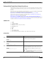
Figure 1-9 shows the ports and slots on the Cisco ISR 4451-Xs.
Hardware Installation Guide for the Cisco 4451-X Integrated Services Router
OL-27644-01
1-18
Chapter 1
Overview of the Cisco 4451-X Integrated Services Router
About Slots and Interfaces
Figure 1-9
Ports and Slots on the Cisco ISR 4451-Xs
1
3
4
5
6
7
8
2
L
16
15
14
13
12
11
10
9
1
Gigabit Ethernet management port
2
USB port 0
3
USB console
4
Auxiliary port
5
Gigabit Ethernet port 0
6
Small-form-factor pluggable (SFP) 0
7
SFP 2
8
Gigabit Ethernet port 2
9
Gigabit Ethernet port 3
10 SFP 3
11 SFP 1
12 Console port
13 Gigabit Ethernet port 1
14 HDD 2 LED
15 HDD 1 LED
16 USB port 1
285701
L
Slot Numbering
Slots are numbered 0, 1 and 2.
•
About Slot 0
•
About Slot 1 and 2
•
Additional Slots
About Slot 0
The following are the main features of Slot 0:
•
Slot 0 is the motherboard and not removable. It is reserved for integrated ports and NIMs.
•
The front panel GE ports (or native interface ports) always reside in slot 0 and bay 0. There are four
ports, and they are called Gigabitethernet 0/0/0, Gigabitethernet 0/0/1, Gigabitethernet 0/0/2, and
Gigabitethernet 0/0/3.
•
PVDM4s do not have an external slot number. Therefore, the nomenclature for PVDM4s always has
0 in the first tuple. For example, the 3-tuple for an PVDM4 might be 0/4/x.
Hardware Installation Guide for the Cisco 4451-X Integrated Services Router
OL-27644-01
1-19
Chapter 1
Overview of the Cisco 4451-X Integrated Services Router
Specifications
About Slot 1 and 2
Slot 1 and slot 2 are NIM slots. All enhanced SM slots start with 1.
Additional Slots
The Cisco ISR 4451-Xs have the following additional slots:
•
P0: Field upgradable power supply slot 0
•
P1: Field upgradable/replaceable power supply slot 1.
•
INT-POE: Internal PoE card slot.
Subslot/Bay Numbering
•
Integrated devices, also known as integrated ports or FPGEs, and integrated NIMs reside in a fixed
section of bay 0.
•
Main board NIMs bays start at bay 1, since the integrated devices and integrated NIMs take up bay 0.
•
The bay numbers for PVDM4s start with the next bay number after the last NIM bay number.
•
The two modular SATA slots share the same bay as the third NIM slot.
Gigabit Ethernet Management
The Cisco ISR 4451-X provides a Gigabit Ethernet Management port, called GE0. This port is the only
1-tuple port on the system. See the <chapter on Ethernet Management in SW Configuration Guide> for
additional information about the Gigabit Ethernet Management port.
About Fixed Interfaces
The router supports fixed interfaces on the motherboard and on service modules. The system treats the
onboard interfaces as if they lived on a virtual NIM plugged into bay 0. In this case, the front panel
GigabitEthernet ports are considered slot 0 bay 0 (0/0/x). The onboard ports on the service module are
slot 1 bay 0 (1/0/x).
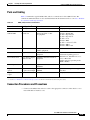
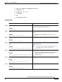
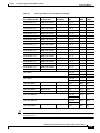
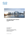
Specifications
The following tables provide Cisco ISR 4451-X specifications.
•
Cisco ISR 4451-X—Table 1-5
Table 1-5
Cisco ISR 4451-X Router Specifications
Description
Specification
Physical
Dimensions (H x W x D)
3.5 x 17.25 x 18.7 in. (88.9 x 438.2 x 474.9 mm), 2 RU height
Hardware Installation Guide for the Cisco 4451-X Integrated Services Router
OL-27644-01
1-20
Chapter 1
Overview of the Cisco 4451-X Integrated Services Router
Specifications
Table 1-5
Cisco ISR 4451-X Router Specifications (continued)
Description
Specification
Weight with AC PS (w/o
modules)
28.5 lbs (12.92 kg)
Weight with dual AC-PoE PS
(w/o modules)
30.0 lbs (13.6 kg)
Weight with dual AC + PoE
adaptor (w/o modules)
38.0-40.0 lbs (17.23-18.14 kg)
Power
AC input power
•
Input voltage
100 to 240 VAC, autoranging
•
Frequency
47 to 63 Hz
•
Input current
5.3 A
•
Input current with PoE
Power Adaptor
7.4 A
•
Surge current
60 A peak and less than 12 Arms per half cycle
Power consumption
•
75 to 320 W, 256 to 1092 BTU/hr (configuration dependent)
With AC-PoE
80 to 750 W, 273 to 753 BTU/hr (configuration dependent)
Ports
Console port
One RJ-45 connector and one mini USB Type B, USB 2.0
compliant
Auxiliary port
RJ-45 connector
USB ports
Two USB Type A, USB 2.0 compliant, 2.5 W (500 mA) max.1
10/100/1000 Gigabit Ethernet
Three RJ-45 connectors (GE0/0, GE0/1, GE0/2), auto-MDIX
SFP
Once an SFP module is installed the adjacent RJ-45 GE connector
is disabled. See xxxx for a list of supported modules.
Environmental
Operating humidity
5 to 85% RH
Operating temperature - up to
5906 ft (1800 m) elevation
32 to 104F (0 to 40C)
Operating temperature - up to
9843 ft (3000 m) elevation
32 to 104F (0 to 40C)
Operating temperature - up to
10,000 ft (3000 m) elevation
32 to 86 F (0 - 30 C)
Operating altitude maximum
10,000 ft (3000 m); China: > 2000 m
Transportation and Storage
Nonoperating temperature
-40 to 158F (-40 to 70C)
Nonoperating humidity
5 to 95% RH
Nonoperating altitude
15,000 ft (4570 m)
Acoustic
Hardware Installation Guide for the Cisco 4451-X Integrated Services Router
OL-27644-01
1-21
Chapter 1
Overview of the Cisco 4451-X Integrated Services Router
Specifications
Table 1-5
Cisco ISR 4451-X Router Specifications (continued)
Description
Specification
Weight with AC PS (w/o
modules)
28.5 lbs (12.92 kg)
Weight with dual AC-PoE PS
(w/o modules)
30.0 lbs (13.6 kg)
Weight with dual AC + PoE
adaptor (w/o modules)
38.0-40.0 lbs (17.23-18.14 kg)
Power
AC input power
•
Input voltage
100 to 240 VAC, autoranging
•
Frequency
47 to 63 Hz
•
Input current
5.3 A
•
Input current with PoE
Power Adaptor
7.4 A
•
Surge current
60 A peak and less than 12 Arms per half cycle
Power consumption
•
75 to 320 W, 256 to 1092 BTU/hr (configuration dependent)
With AC-PoE
80 to 750 W, 273 to 753 BTU/hr (configuration dependent)
Ports
Console port
One RJ-45 connector and one mini USB Type B, USB 2.0
compliant
Auxiliary port
RJ-45 connector
USB ports
Two USB Type A, USB 2.0 compliant, 2.5 W (500 mA) max.1
10/100/1000 Gigabit Ethernet
Three RJ-45 connectors (GE0/0, GE0/1, GE0/2), auto-MDIX
SFP
Once an SFP module is installed the adjacent RJ-45 GE connector
is disabled. See xxxx for a list of supported modules.
Environmental
Operating humidity
5 to 85% RH
Operating temperature - up to
5906 ft (1800 m) elevation
32 to 104F (0 to 40C)
Operating temperature - up to
9843 ft (3000 m) elevation
32 to 104F (0 to 40C)
Operating temperature - up to
10,000 ft (3000 m) elevation
32 to 86 F (0 - 30 C)
Operating altitude maximum
10,000 ft (3000 m); China: > 2000 m
Transportation and Storage
Nonoperating temperature
-40 to 158F (-40 to 70C)
Nonoperating humidity
5 to 95% RH
Nonoperating altitude
15,000 ft (4570 m)
Acoustic
Hardware Installation Guide for the Cisco 4451-X Integrated Services Router
OL-27644-01
1-22
Chapter 1
Overview of the Cisco 4451-X Integrated Services Router
Specifications
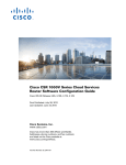
Table 1-5
Cisco ISR 4451-X Router Specifications (continued)
Description
Specification
Acoustic: Sound Pressure
(Typical/Maximum)
54.4 to 67.4 dBA
Acoustic: Sound Power
(Typical/Maximum)
62.6 to 74.5 dBA
Regulatory
Safety compliance
IEC 60950-1, Safety of information technology equipment
EN 60950-1, Safety of information technology equipment
UL 60950-1, Standard for safety for information technology
equipment [US]
CAN/CSA C22.2 No. 60950-1, Safety of information technology
equipment including electrical business equipment [Canada]
AS/NZS 60950.1 2003
GB 4943[PRC]
IEC60950, 2nd Edition [Mexico]
For detailed compliance information, see the Regulatory
Compliance and Safety Information for the Cisco 4451-X
Integrated Services Router document
Hardware Installation Guide for the Cisco 4451-X Integrated Services Router
OL-27644-01
1-23
Chapter 1
Overview of the Cisco 4451-X Integrated Services Router
Specifications
Table 1-5
Cisco ISR 4451-X Router Specifications (continued)
Description
Specification
Immunity compliance
CISPR24 ITE-Immunity characteristics, Limits and methods of
measurement
EN 55024 ITE-Immunity characteristics, Limits and methods of
measurement
EN 50082-1 Electromagnetic compatibility - Generic immunity
standard - Part 1
EN 300-386 Electromagnetic compatibility for TNE
SD/EMI
EN 61000-6-1
For detailed compliance information, see the Regulatory
Compliance and Safety Information for the Cisco 4451-X
Integrated Services Router document
EMC compliance
EN 55022, class A
CISPR22, class A
CFR47, Part 15, Subpart B, class A
EN 300386, Class A
AS/NZS CISPR22, Class A
VCCI, Class A
SD/EMI, Class A
Harmonic Current Emission
EN 61000-3-2 for EUT Power requirements <16A
EN 61000-3-12 for EUT Power requirements >16A
Voltage Fluctuation and Flicker
EN 61000-3-3 for EUT Power requirements <16
EN 61000-3-11 for EUT Power requirements >16A
For detailed compliance information, see the Regulatory
Compliance and Safety Information for the Cisco 4451-X
Integrated Services Router document.
1. 480 Mb/s individually, bandwidth is shared when both are used.
Hardware Installation Guide for the Cisco 4451-X Integrated Services Router
OL-27644-01
1-24
Chapter 1
Overview of the Cisco 4451-X Integrated Services Router
Periodic Inspection and Cleaning
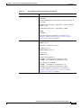
Periodic Inspection and Cleaning
Periodic inspection and cleaning of the external surface of the router is recommended to minimize the
negative impact of environmental dust or debris. The frequency of inspection and cleaning is dependent
upon the severity of the environmental conditions, but a minimum of every six months is recommended.
Cleaning involves vacuuming of router air intake and exhaust vents. See the “Fans, Ventilation, and
Airflow” section on page 1-17.
Caution
Sites with ambient temperatures consistently above 25°C or 77°F and with potentially high levels of dust
or debris may require periodic preventative maintenance cleaning.
Hardware Installation Guide for the Cisco 4451-X Integrated Services Router
OL-27644-01
1-25
CH A P T E R
2
Preparing for Router Installation
This document provides preinstallation information, such as recommendations and requirements that
should be before installing your router. See the following sections to prepare for installation:
•
Safety Recommendations, page 2-5
•
General Site Requirements, page 2-7
•
Rack Requirements, page 2-9
•
Router Environmental Requirements, page 2-10
•
Network Cabling Specifications, page 2-11
•
Installation Checklist, page 2-16
•
Creating a Site Log, page 2-17
To see translated warnings that appear in this publication, see the Regulatory Compliance and Safety
Information for the Cisco 4451-X Integrated Services Routers document.
Standard Warning Statements
This section describes the warning definition and then lists core safety warnings grouped by topic.
Warning
This warning symbol means danger. You are in a situation that could cause bodily injury. Before you
work on any equipment, be aware of the hazards involved with electrical circuitry and be familiar
with standard practices for preventing accidents. Use the statement number provided at the end of
each warning to locate its translation in the translated safety warnings that accompanied this device.
Note: SAVE THESE INSTRUCTIONS
Statement 1071
General Safety Warnings
Warning
Read the installation instructions before you connect the system to its power source. Statement 1004
Hardware Installation Guide for the Cisco 4451-X Integrated Services Router
OL-27644-01
2-1
Chapter 2
Preparing for Router Installation
Standard Warning Statements
Warning
Ultimate disposal of this product should be handled according to all national laws and regulations.
Statement 1040
Warning
Installation of the equipment must comply with local and national electrical codes. Statement 1074
Warning
To comply with the Class A emissions requirements shielded twisted pair T1/E1 cables must be used
for SPA-8-Port Channelized T1/E1 SPA (SPA-8XCHT1/E1) on the Cisco ISR 4451-Xs. EN55022/CISPR22
Statement
Warning
To comply with Class A emissions requirements- shielded management Ethernet, CON, and AUX
cables on the Cisco ISR 4451-Xs must be used.
Warning
Power cable and AC adapter - When installing the product, please use the provided or designated
connection cables/power cables/AC adaptors. Using any other cables or adapters could cause a
malfunction or a fire. Electrical Appliance and Material Safety Law prohibits the use of certified
cables (that have the ‘UL’ shown on the code) for any other electrical devices than products
designated by Cisco. The use of cables that are certified by Electrical Appliance and Material Safety
Law (that have ‘PSE’ shown on the code) is not limited to Cisco-designated products. Statement 371
Warning
Only trained and qualified personnel should be allowed to install or replace this equipment
Statement 1030
Warning
This product relies on the building’s installation for short-circuit (overcurrent) protection. Ensure that
the protective device is rated not greater than: AC power supplies for the Cisco ISR 4451-X. Statement
1005
Warning
This product requires short-circuit (overcurrent) protection to be provided as part of the building
installation. Install only in accordance with national and local wiring regulations. Statement 1045
Warning
This unit may have more than one power supply connection. All connections must be removed to
de-energize the unit. Statement 1028
Warning
This unit is intended for installation in restricted access areas. A restricted access area can be
accessed only through the use of a special tool, lock and key, or other means of security. Statement
1017
Hardware Installation Guide for the Cisco 4451-X Integrated Services Router
OL-27644-01
2-2
Chapter 2
Preparing for Router Installation
Standard Warning Statements
Warning
The plug-socket combination must be accessible at all times, because it serves as the main
disconnecting device. Statement 1019
Warning
Hazardous voltage or energy may be present on the DC power terminals. Always replace cover when
terminals are not in service. Be sure uninsulated conductors are not accessible when cover is in
place. Statement 1075
Warning
Use copper conductors only. Statement 1025
Warning
This equipment must be grounded. Never defeat the ground conductor or operate the equipment in the
absence of a suitably installed ground conductor. Contact the appropriate electrical inspection
authority or an electrician if you are uncertain that suitable grounding is available. Statement 1024
Warning
Hazardous voltage or energy is present on the backplane when the system is operating. Use caution
when servicing. Statement 1034
Warning
Class 1 laser product. Statement 1008
Warning
Class 1 LED product. Statement 1027
Warning
Laser radiation is present when the system is open. Statement 1009
Warning
Do not stare into the laser beam. Statement 1010
Warning
Class I(CDRH) and Class 1M (IEC) laser products. Statement 1055
Warning
Invisible laser radiation may be emitted from the end of the unterminated fiber cable or connector. Do
not view directly with optical instruments. Viewing the laser output with certain optical instruments
(for example, eye loupes, magnifiers, and microscopes) within a distance of 100 mm may pose an eye
hazard. Statement 1056
Warning
There is the danger of explosion if the battery is replaced incorrectly. Replace the battery only with
the same or equivalent type recommended by the manufacturer. Dispose of used batteries according
to the manufacturer’s instructions. Statement 1015
Hardware Installation Guide for the Cisco 4451-X Integrated Services Router
OL-27644-01
2-3
Chapter 2
Preparing for Router Installation
Standard Warning Statements
Warning
Do not touch or bridge the metal contacts on the battery. Unintentional discharge of the batteries can
cause serious burns. Statement 341
Warning
To prevent personal injury or damage to the chassis, never attempt to lift or tilt the chassis using the
handles on modules (such as power supplies, fans, or cards); these types of handles are not designed
to support the weight of the unit. Statement 1032
Warning
To prevent the system from overheating, do not operate it in an area that exceeds the maximum
recommended ambient temperature of: 40 degrees C. Statement 1047
Warning
This equipment must be externally grounded using a customer-supplied ground wire before power is
applied. Contact the appropriate electrical inspection authority or an electrician if you are uncertain
that suitable grounding is available. Statement 366
Warning
Blank faceplates and cover panels serve three important functions: they prevent exposure to
hazardous voltages and currents inside the chassis; they contain electromagnetic interference (EMI)
that might disrupt other equipment; and they direct the flow of cooling air through the chassis. Do not
operate the system unless all cards, faceplates, front covers, and rear covers are in place. Statement
1029
Warning
Only trained and qualified personnel should be allowed to install, replace, or service this equipment.
Statement 1030
Warning
This equipment must be installed and maintained by service personnel as defined by AS/NZS 3260.
Incorrectly connecting this equipment to a general-purpose outlet could be hazardous. The
telecommunications lines must be disconnected 1) before unplugging the main power connector or 2)
while the housing is open, or both. Statement 1043
Warning
This unit might have more than one power supply connection. All connections must be removed to
de-energize the unit. Statement 1028
Warning
Hazardous network voltages are present in WAN ports regardless of whether power to the unit is OFF
or ON. To avoid electric shock, use caution when working near WAN ports. When detaching cables,
detach the end away from the unit first. Statement 1026
Warning
Before opening the unit, disconnect the telephone-network cables to avoid contact with
telephone-network voltages. Statement 1041
Hardware Installation Guide for the Cisco 4451-X Integrated Services Router
OL-27644-01
2-4
Chapter 2
Preparing for Router Installation
Safety Recommendations
Warning
Do not use this product near water; for example, near a bath tub, wash bowl, kitchen sink or laundry
tub, in a wet basement, or near a swimming pool. Statement 1035
Warning
Never install telephone jacks in wet locations unless the jack is specifically designed for
wet locations. Statement 1036
Warning
No user-serviceable parts inside. Do not open. Statement 1073
Warning
Never touch uninsulated telephone wires or terminals unless the telephone line has been
disconnected at the network interface. Statement 1037
Warning
Avoid using a telephone (other than a cordless type) during an electrical storm. There may be a remote
risk of electric shock from lightning. Statement 1038
Warning
To report a gas leak, do not use a telephone in the vicinity of the leak. Statement 1039
Safety Recommendations
Follow these guidelines to ensure general safety:
•
Review the safety warnings listed in Regulatory Compliance and Safety Information for the
Cisco 4451-X Integrated Services Routers that comes with your Cisco ISR 4451-X, before
installing, configuring, or maintaining the router.
•
Never attempt to lift an object that might be too heavy for you to lift by yourself.
•
Keep the chassis area clear and dust-free during and after installation.
•
If you remove the chassis cover, put it in a safe place.
•
Keep tools and chassis components away from walk areas.
•
Do not wear loose clothing that could get caught in the chassis. Fasten your tie or scarf and roll up
your sleeves.
•
Wear safety glasses when working under conditions that might be hazardous to your eyes.
•
Do not perform any action that creates a hazard to people or makes the equipment unsafe.
Safety with Electricity
Warning
This unit might have more than one power supply connection. All connections must be removed to
de-energize the unit. Statement 1028
Hardware Installation Guide for the Cisco 4451-X Integrated Services Router
OL-27644-01
2-5
Chapter 2
Preparing for Router Installation
Safety Recommendations
Warning
Do not work on the system or connect or disconnect cables during periods of lightning activity.
Statement 1001
Warning
Read the installation instructions before connecting the system to the power source. Statement 1004
Warning
The covers are an integral part of the safety design of the product. Do not operate the unit without the
covers installed. Statement 1077
Follow these guidelines when working on equipment powered by electricity:
•
Locate the emergency power-off switch in the room in which you are working. If an electrical
accident occurs, you can quickly turn off the power.
•
Disconnect all power before doing the following:
– Installing or removing a chassis
– Working near power supplies
•
Look carefully for possible hazards in your work area, such as moist floors, ungrounded power
extension cables, frayed power cords, and missing safety grounds.
•
Do not work alone if hazardous conditions exist.
•
Never assume that power is disconnected from a circuit. Always check.
•
Never open the enclosure of the internal power supply.
•
If an electrical accident occurs, proceed as follows:
– Use caution; do not become a victim yourself.
– Turn off power to the device.
– If possible, send another person to get medical aid. Otherwise, assess the condition of the victim
and then call for help.
– Determine if the person needs rescue breathing or external cardiac compressions; then take
appropriate action.
In addition, use the following guidelines when working with any equipment that is disconnected from a
power source but still connected to telephone wiring or other network cabling:
•
Never install telephone wiring during a lightning storm.
•
Never install telephone jacks in wet locations unless the jack is specifically designed for it.
•
Never touch uninsulated telephone wires or terminals unless the telephone line is disconnected at
the network interface.
•
Use caution when installing or modifying telephone lines.
•
Remove power cables from all installed power supplies before opening the chassis.
Hardware Installation Guide for the Cisco 4451-X Integrated Services Router
OL-27644-01
2-6
Chapter 2
Preparing for Router Installation
General Site Requirements
Preventing Electrostatic Discharge Damage
Electrostatic discharge (ESD) can damage equipment and impair electrical circuitry. It can occur if
electronic printed circuit cards are improperly handled and can cause complete or intermittent failures.
Always follow ESD prevention procedures when removing and replacing modules:
Caution
•
Ensure that the router chassis is electrically connected to ground.
•
Wear an ESD-preventive wrist strap, ensuring that it makes good skin contact. Connect the clip to
an unpainted surface of the chassis frame to channel unwanted ESD voltages safely to ground. To
guard against ESD damage and shocks, the wrist strap and cord must operate effectively.
•
If no wrist strap is available, ground yourself by touching a metal part of the chassis.
For the safety of your equipment, periodically check the resistance value of the antistatic strap. It should
be between 1 and 10 megohms (Mohm).
General Site Requirements
This section describes the requirements your site must meet for safe installation and operation of your
router. Ensure that the site is properly prepared before beginning installation. If you are experiencing
shutdowns or unusually high errors with your existing equipment, this section can also help you isolate
the cause of failures and prevent future problems.
General Precautions
Observe the following general precautions when using and working with your Cisco ISR 4451-X.
•
Keep your system components away from radiators and heat sources and do not block cooling vents.
•
Do not spill food or liquids on your system components and never operate the product in a wet
environment.
•
Do not push any objects into the openings of your system components. Doing so can cause fire or
electric shock by shorting out interior components.
•
Position system cables and power supply cables carefully. Route system cables and the power supply
cable and plug so that they cannot be stepped on or tripped over. Be sure that nothing else rests on
your system component cables or power cable.
•
Do not modify power cables or plugs. Consult a licensed electrician or your power company for site
modifications. Always follow your local and national wiring rules.
•
If you turn off your system, wait at least 30 seconds before turning it on again to avoid system
component damage.
Site Selection Guidelines
The Cisco ISR 4451-Xs require specific environmental operating conditions. Temperature, humidity,
altitude, and vibration can affect the performance and reliability of the router. The following sections
provide specific information to help you plan for the proper operating environment.
Hardware Installation Guide for the Cisco 4451-X Integrated Services Router
OL-27644-01
2-7
Chapter 2
Preparing for Router Installation
General Site Requirements
The Cisco ISR 4451-Xs are designed to meet the industry EMC, safety, and environmental standards
described in the Regulatory, Safety, and Compliance Information for Cisco 4451-X Integrated Services
Routers document.
Site Environmental Requirements
Environmental monitoring in the Cisco ISR 4451-X protects the system and components from damage
caused by excessive voltage and temperature conditions. To ensure normal operation and avoid
unnecessary maintenance, plan and prepare your site configuration before installation. After installation,
make sure the site maintains the environmental characteristics as shown in Table 2-1.
Table 2-1
Cisco ISR 4451-X Environmental Tolerances
Environmental Characteristic
Minimum
Maximum
Steady State Operating
0 degree C
50 degree C
(50 degrees C at 10,000
feet)
Storage
–20 degrees C
+70 degrees C
Humidity operating (noncondensing)
10%
90%
Humidity nonoperating (noncondensing)
5%
95%
Altitude operating: over allowable temperature
range (0 to 50 degrees C)
–500 feet
10,000 feet
Altitude, nonoperating: over allowable temperature
range
–1000 feet
50,000 feet
Thermal shock non-operating with change over time –25 degrees C
of 3 minute
+70 degrees C
Thermal Shock - Operating at 2.5 degree C per
minute
+50 degrees C
0 degrees C
Hardware Installation Guide for the Cisco 4451-X Integrated Services Router
OL-27644-01
2-8
Chapter 2
Preparing for Router Installation
Rack Requirements
Physical Characteristics
Be familiar with the physical characteristics of the Cisco ISR 4451-X to assist you in placing the system
in the proper location.
Table 2-2 shows the weight and dimensions of the Cisco ISR 4451-X.
Table 2-2
Physical Characteristics of Cisco ISR 4451-Xs
Characteristics
Cisco ISR 4451-Xs
Height
3.5 in. (8.89 cm.)—2RU rack-mount
Width
17.25 in. (43.815 cm.)—19-inch rack-mount
Depth
18.7 in. (47.498 cm.)
(including card handles, cable-management brackets, power supply
handles)
Weight
38-40 lbs (17.23-18.14 kg)
The following list describes additional Cisco ISR 4451-X chassis characteristics:
•
Chassis height meets EIA-310 rack spacing 2RU (3.5 inches/88.90 mm.), universal rack-mount
•
Chassis width meets EIA-310 19-inch (17.25 inches/438.15 mm) wide with rack brackets
•
Cable-management brackets at each Cisco ISR 4451-X locations can hold 16 ports of STP/UTP RJ
45 cables
•
Cable-management brackets allow a bend radius of 1.5 inches for cables
•
Adjustable rack-mount brackets allow for a front to rear rail variance distance of 15.50/394mm to
19.00/482.6mm
Rack Requirements
Some Cisco routers include brackets for use with a 19-inch rack or, if specified in your order, optional
larger brackets for use with a 23-inch rack.
The following information can help you plan your equipment rack configuration:
•
Allow clearance around the rack for maintenance.
•
Allow at least one rack unit of vertical space between routers.
•
Enclosed racks must have adequate ventilation. Ensure that the rack is not congested, because each
router generates heat. An enclosed rack should have louvered sides and a fan to provide cooling air.
Heat generated by equipment near the bottom of the rack can be drawn upward into the intake ports
of the equipment above it.
•
When mounting a chassis in an open rack, ensure that the rack frame does not block the intake or
exhaust ports. If the chassis is installed on slides, check the position of the chassis when it is seated
in the rack.
Hardware Installation Guide for the Cisco 4451-X Integrated Services Router
OL-27644-01
2-9
Chapter 2
Preparing for Router Installation
Router Environmental Requirements
Router Environmental Requirements
Cisco ISR 4451-Xs can be placed on a desktop or installed in a rack. The location of your router and the
layout of your equipment rack or wiring room are extremely important considerations for proper
operation. Equipment placed too close together, inadequate ventilation, and inaccessible panels can
cause malfunctions and shutdowns, and can make maintenance difficult. Plan for access to both front
and rear panels of the router.
When planning your site layout and equipment locations, refer to the “General Site Requirements”
section on page 2-7, section. If you are currently experiencing shutdowns or an unusually high number
of errors with your existing equipment, these precautions and recommendations may help you isolate the
cause of failure and prevent future problems.
•
Ensure that the room where your router operates has adequate air circulation. Electrical equipment
generates heat. Without adequate air circulation, ambient air temperature may not cool equipment
to acceptable operating temperatures.
•
Always follow ESD-prevention procedures described in the “Preventing Electrostatic Discharge
Damage” section on page 2-7 to avoid damage to equipment. Damage from static discharge can
cause immediate or intermittent equipment failure.
•
Ensure that the chassis cover and module rear panels are secure. All empty network module slots,
interface card slots, and power supply bays must have filler panels installed. The chassis is designed
to allow cooling air to flow within it, through specially designed cooling slots. A chassis with
uncovered openings permits air leaks, which may interrupt and reduce the flow of air across internal
components.
•
Baffles can help to isolate exhaust air from intake air, which also helps to draw cooling air through
the chassis. The best placement of the baffles depends on the airflow patterns in the rack, which can
be found by experimenting with different configurations.
•
When equipment installed in a rack (particularly in an enclosed rack) fails, try operating the
equipment by itself, if possible. Power off other equipment in the rack (and in adjacent racks) to
allow the router under test a maximum of cooling air and clean power.
Hardware Installation Guide for the Cisco 4451-X Integrated Services Router
OL-27644-01
2-10
Chapter 2
Preparing for Router Installation
Power Guidelines and Requirements
Power Guidelines and Requirements
Check the power at your site to ensure that you are receiving “clean” power (free of spikes and noise).
Install a power conditioner if necessary.
The AC power supply includes the following features:
•
Autoselects either 110 V or 220 V operation.
•
All units include a 6-foot (1.8-meter) electrical power cord. (A label near the power inlet indicates
the correct voltage, frequency [AC-powered systems only], current draw, and power dissipation for
the unit.)
Table 2-3 lists power requirements for the Cisco ISR 4451-Xs.
Table 2-3
Power Requirements for Cisco ISR 4451-Xs
Router
Power Source
Input Power
Input Voltage
Tolerance Limits
Cisco ISR 4451-X
AC
100 — 240 VAC, 3.0 A, 50 — 60 Hz
90 — 264 VAC
Cisco ISR 4451-X with
PoE
AC
100 — 240 VAC, 8.0 A, 50 — 60 Hz
90 — 264 VAC
Network Cabling Specifications
The following sections describe the cables needed to install your Cisco ISR 4451-X in the following
sections:
•
Console and Auxiliary Port Considerations, page 2-12
•
Preparing for Network Connections, page 2-14
Hardware Installation Guide for the Cisco 4451-X Integrated Services Router
OL-27644-01
2-11
Chapter 2
Preparing for Router Installation
Network Cabling Specifications
Console and Auxiliary Port Considerations
The router includes an asynchronous serial console port and an auxiliary port. The console and auxiliary
ports provide access to the router either locally using a console terminal connected to the console port,
or remotely using a modem connected to the auxiliary port. This section discusses important cabling
information to consider before connecting the router to a console terminal or modem.
The main difference between the console and auxiliary ports is that the auxiliary port supports hardware
flow control and the console port does not. Flow control paces the transmission of data between a
sending device and a receiving device. Flow control ensures that the receiving device can absorb the data
sent to it before the sending device sends more. When the buffers on the receiving device are full, a
message is sent to the sending device to suspend transmission until the data in the buffers has been
processed. Because the auxiliary port supports flow control, it is ideally suited for use with the
high-speed transmissions of a modem. Console terminals send data at speeds slower than modems do;
therefore, the console port is ideally suited for use with console terminals.
Console Port Connections
The router has both EIA/TIA-232 asynchronous (RJ-45) and USB 5-pin mini Type B, 2.0 compliant
serial console ports. The console ports do not have any hardware flow control. Shielded USB cables with
properly terminated shields are recommended.
EIA/TIA-232
Depending on the cable and the adapter used, this port appears as a DTE or DCE device at the end of the
cable. Only one port can be used at the same time.
The default parameters for the console port are 9600 baud, 8 data bits, 1 stop bit, and no parity. The
console port does not support hardware flow control. For detailed information about installing a console
terminal, see the “Connecting to a Console Terminal or Modem” section on page 3-14.
For cable and port pinouts, see the Cisco Modular Access Router Cable Specifications document located
on Cisco.com.
USB Serial Console
The USB serial console port connects directly to the USB connector of a PC using a USB Type A to 5-pin
mini USB Type-B cable. The USB Console supports full speed (12Mb/s) operation. The console port
does not support hardware flow control.
Note
Always use shielded USB cables with a properly terminated shield.
The default parameters for the console port are 9600 baud, 8 data bits, no parity, and 1 stop bit. For
detailed information about installing a console terminal, see the “Connecting to a Console Terminal or
Modem” section on page 3-14.
For operation with a Microsoft Windows OS version older than Windows 7, the Cisco Windows USB
Console Driver must be installed on any PC connected to the console port. If the driver is not installed,
prompts guide you through a simple installation process. For detailed information about installing the
Cisco Windows USB Console Driver see “Installing the Cisco Microsoft Windows USB Device Driver”
section on page 3-16.
Hardware Installation Guide for the Cisco 4451-X Integrated Services Router
OL-27644-01
2-12
Chapter 2
Preparing for Router Installation
Network Cabling Specifications
The Cisco Windows USB Console Driver allows plugging and unplugging the USB cable from the
console port without affecting Windows HyperTerminal operations. No special drivers are needed for
Mac OS X or Linux.
Only one console port can be active at a time. When a cable is plugged into the USB console port, the
RJ-45 port becomes inactive. Conversely, when the USB cable is removed from the USB port, the RJ-45
port becomes active.
Baud rates for the USB console port are 1200, 2400, 4800, 9600, 19200, 38400, 57600, and 115200 bps.
Note
4-pin mini USB Type-B connectors are easily confused with 5-pin mini USB Type-B connectors.
Only the 5-pin mini USB Type-B is supported.
USB Console OS Compatibility
•
Windows 2000, Window XP 32 bit, Windows Vista 32 bit
•
Mac OS X version 10.5.4
•
Redhat / Fedora Core 10 with kernel 2.6.27.5-117
•
Ubuntu 8.10 with kernel 2.6.27-11
•
Debian 5.0 with kernel 2.6
•
Suse 11.1 with kernel 2.6.27.7-9
Auxiliary Port Connections
The router has an EIA/TIA-232 asynchronous serial auxiliary port (RJ-45) that supports flow control.
Depending on the cable and the adapter used, this port appears as a DTE or DCE device at the end of the
cable.
For connection to a modem, your must use an RJ-45-to-DB-25 adapter cable. This cable is orderable
separately along with a DB-9-to-DB-25 adapter.
For detailed information about connecting devices to the auxiliary port, see the “Connecting to a Console
Terminal or Modem” section on page 3-14.
For cable and port pinouts, see the Cisco Modular Access Router Cable Specifications document at
Cisco.com.
Hardware Installation Guide for the Cisco 4451-X Integrated Services Router
OL-27644-01
2-13
Chapter 2
Preparing for Router Installation
Required Tools and Equipment for Installation and Maintenance
Preparing for Network Connections
When setting up your router, consider distance limitations and potential electromagnetic interference
(EMI) as defined by the applicable local and international regulations.
Network connection considerations are provided for:
•
Ethernet Connections, page 2-14
See the following online document for more information about network connections and interfaces:
•
Warning
Cisco Modular Access Router Cable Specifications
To avoid electric shock, do not connect safety extra-low voltage (SELV) circuits to telephone-network
voltage (TNV) circuits. LAN ports contain SELV circuits, and WAN ports contain TNV circuits. Some
LAN and WAN ports both use RJ-45 connectors. Statement 1021
Ethernet Connections
The IEEE has established Ethernet as standard IEEE 802.3. Cisco ISR 4451-Xs support the following
Ethernet implementations:
•
1000BASE-T—1000 Mb/s full-duplex transmission over a Category 5 or better unshielded
twisted-pair (UTP) cable. Supports the Ethernet maximum length of 328 feet (100 meters).
•
100BASE-T—100 Mb/s full-duplex transmission over a Category 5 or better unshielded
twisted-pair (UTP) cable. Supports the Ethernet maximum length of 328 feet (100 meters).
•
10BASE-T—10 Mb/s full-duplex transmission over a Category 5 or better unshielded twisted-pair
(UTP) cable. Supports the Ethernet maximum length of 328 feet (100 meters).
See the Cisco Modular Access Router Cable Specifications document at Cisco.com for information
about Ethernet cables, connectors, and pinouts.
Required Tools and Equipment for Installation and Maintenance
Warning
Only trained and qualified personnel should be allowed to install, replace, or service this equipment.
Statement 1030
Warning
This equipment must be installed and maintained by service personnel as defined by AS/NZS 3260.
Incorrectly connecting this equipment to a general-purpose outlet could be hazardous. The
telecommunications lines must be disconnected 1) before unplugging the main power connector or 2)
while the housing is open, or both. Statement 1043
Hardware Installation Guide for the Cisco 4451-X Integrated Services Router
OL-27644-01
2-14
Chapter 2
Preparing for Router Installation
Required Tools and Equipment for Installation and Maintenance
You need the following tools and equipment to install and upgrade the router and its components:
•
ESD-preventive cord and wrist strap
•
Number 2 Phillips screwdriver
•
Phillips screwdrivers: small, 3/16-in. (4 to 5 mm) and medium, 1/4-in. (6 to 7 mm)
– To install or remove modules
– To remove the cover, if you are upgrading memory or other components
•
Screws that fit your rack
•
Wire crimper
•
Wire for connecting the chassis to an earth ground:
– AWG 6 (13 mm 2) wire for NEBS-compliant chassis grounding
– AWG 14 (2 mm 2) or larger wire for NEC-compliant chassis grounding
– AWG 18 (1 mm 2) or larger wire for EN/IEC 60950-compliant chassis grounding
•
For NEC-compliant grounding, an appropriate user-supplied ring terminal, with an inner diameter
of 1/4 in. (5 to 7 mm)
In addition, depending on the type of modules you plan to use, you might need the following equipment
to connect a port to an external network:
•
Cables for connection to the WAN and LAN ports (dependent on configuration)
Note
For more information on cable specifications, see the Cisco Modular Access Router Cable
Specifications document at Cisco.com.
•
Ethernet hub or PC with a network interface card for connection to an Ethernet (LAN) port.
•
Console terminal (an ASCII terminal or a PC running HyperTerminal or similar terminal emulation
software) configured for 9600 baud, 8 data bits, 1 stop bit, no flow control, and no parity.
•
Modem for connection to the auxiliary port for remote administrative access (optional).
•
Data service unit (DSU) or channel service unit/data service unit (CSU/DSU) as appropriate for
serial interfaces.
•
External CSU for any CT1/PRI modules without a built-in CSU.
Hardware Installation Guide for the Cisco 4451-X Integrated Services Router
OL-27644-01
2-15
Chapter 2
Preparing for Router Installation
Installation Checklist
Installation Checklist
The sample installation checklist lists items and procedures for installing a new router. Make a copy of
this checklist and mark the entries when completed. Include a copy of the checklist for each router in
your site log (described in the next section, “Creating a Site Log”).
Installation checklist for site_____________________________________________
Router name_______________________________________________________
Task
Verified by
Date
Installation checklist copied
Background information placed in Site Log
Site power voltages verified
Installation site power check completed
Required tools available
Additional equipment available
Router received
Router quick start guide received
Regulatory Compliance and Safety Information for the
Cisco 4451-X Integrated Services Routers document
received
Product registration card received
Cisco.com contact information label received
Chassis components verified
Initial electrical connections established
ASCII terminal (for local configuration) or
modem (for remote configuration) available
Signal distance limits verified
Startup sequence steps completed
Initial operation verified
Software image verified
Hardware Installation Guide for the Cisco 4451-X Integrated Services Router
OL-27644-01
2-16
Chapter 2
Preparing for Router Installation
Creating a Site Log
Creating a Site Log
The Site Log provides a record of all actions related to the router. Keep it in an accessible place near the
chassis where anyone who performs tasks has access to it. Use the installation checklist to verify steps
in the installation and maintenance of the router. Site Log entries might include the following
information:
•
Installation progress—Make a copy of the installation checklist and insert it into the site log. Make
entries as each procedure is completed.
•
Upgrade and maintenance procedures—Use the site log as a record of ongoing router maintenance
and expansion history. A site log might include the following events:
– Installation of network modules
– Removal or replacement of network modules and other upgrades
– Configuration changes
– Maintenance schedules and requirements
– Maintenance procedures performed
– Intermittent problems
– Comments and notes
Inspect all items for shipping damage. If anything appears to be damaged or if you encounter problems
installing or configuring your router, contact customer service. Warranty, service, and support
information is in the quick start guide that shipped with your router, or in the Preface of this guide. See
the “Obtaining Documentation and Submitting a Service Request” section on page -xviii.
Hardware Installation Guide for the Cisco 4451-X Integrated Services Router
OL-27644-01
2-17
CH A P T E R
3
Installing and Connecting the Router
This document describes how to install and connect the Cisco 4451-X Integrated Services Routers
(ISRs) to LAN, WAN, and Voice networks. The following sections provide technical details.
•
Installing the Router, page 3-4
•
Chassis Grounding, page 3-11
•
Connecting Power, page 3-12
•
Connecting to a Console Terminal or Modem, page 3-14
•
Installing the Cisco Microsoft Windows USB Device Driver, page 3-16
•
Uninstalling the Cisco Microsoft Windows USB Driver, page 3-18
•
Connecting to the Auxiliary Port, page 3-19
•
Connecting WAN, LAN, and Voice Interfaces, page 3-20
Warning
To see translations of the warnings that appear in this publication, see the Regulatory Compliance and
Safety Information for the Cisco 4451-X Integrated Services Routers document. Only trained and
qualified personnel should be allowed to install, replace, or service this equipment. Statement 1030
Warning
This unit might have more than one power supply connection. All connections must be removed to
de-energize the unit. Statement 1028
Warning
Blank faceplates and cover panels serve three important functions: they prevent exposure to
hazardous voltages and currents inside the chassis; they contain electromagnetic interference (EMI)
that might disrupt other equipment; and they direct the flow of cooling air through the chassis. Do not
operate the system unless all cards, faceplates, front covers, and rear covers are in place. Statement
1029
Warning
Hazardous network voltages are present in WAN ports regardless of whether power to the unit is OFF
or ON. To avoid electric shock, use caution when working near WAN ports. When detaching cables,
detach the end away from the unit first. Statement 1026
Cisco 4400 Series Hardware Installation Guide
OL-27644-01
3-1
Chapter 3
Installing and Connecting the Router
Warning
This equipment must be grounded. Never defeat the ground conductor or operate the equipment in the
absence of a suitably installed ground conductor. Contact the appropriate electrical inspection
authority or an electrician if you are uncertain that suitable grounding is available. Statement 1024
Warning
Before opening the unit, disconnect the telephone-network cables to avoid contact with
telephone-network voltages. Statement 1041
Warning
Do not use this product near water; for example, near a bath tub, wash bowl, kitchen sink or laundry
tub, in a wet basement, or near a swimming pool. Statement 1035
Warning
Never install telephone jacks in wet locations unless the jack is specifically designed for
wet locations. Statement 1036
Warning
Never touch uninsulated telephone wires or terminals unless the telephone line has been
disconnected at the network interface. Statement 1037
Warning
Avoid using a telephone (other than a cordless type) during an electrical storm. There may be a remote
risk of electric shock from lightning. Statement 1038
Warning
To report a gas leak, do not use a telephone in the vicinity of the leak. Statement 1039
Warning
This unit is intended for installation in restricted access areas. A restricted access area can be
accessed only through the use of a special tool, lock and key, or other means of security.
Statement 1017
Warning
Blank faceplates and cover panels serve three important functions: they prevent exposure to
hazardous voltages and currents inside the chassis; they contain electromagnetic interference (EMI)
that might disrupt other equipment; and they direct the flow of cooling air through the chassis. Do not
operate the system unless all cards, faceplates, front covers, and rear covers are in place.
Statement 1029
Warning
The covers are an integral part of the safety design of the product. Do not operate the unit without the
covers installed. Statement 1077
Cisco 4400 Series Hardware Installation Guide
OL-27644-01
3-2
Chapter 3
Installing and Connecting the Router
What You Need to Know
What You Need to Know
CLI Console Access
Use the USB console port on the router to access the Cisco Internet Operating System (IOS-XE)
command line interface (CLI) on the router and perform configuration tasks. A terminal emulation
program is required to establish communication between the router and a PC. See the “Connecting to a
Console Terminal or Modem” section on page 3-14 for instructions.
Note
A Microsoft Windows USB driver must be installed before you establish physical connectivity
between the router and the PC.
Slot and Port Numbers
Cisco ISR 4451-Xs have built in ports and new slots. The new slots accommodate new modules and
interface cards; SMs, NIMs, PVDM4s, and the Cisco E-Series Server Modules. See the “About Slots and
Interfaces” section on page 1-17 for slot and port numbering.
Software Licenses
To use all the features on the Cisco ISR 4451-X, you must purchase a software package.
See the ”Licensing” section of the Software Configuration Guide for the Cisco 4451-X Integrated
Services Routers for more information.
Before You Begin
Before installing and connecting a Cisco Integrated Services Router, read the safety warnings and gather
the following tools and equipment.
•
ESD-preventive cord and wrist strap
•
Number 2 Phillips screwdriver
•
Flat-blade screwdrivers: small, 3/16-in. (4 to 5 mm) and medium, 1/4-in. (6 to 7 mm)
– To install or remove modules
– To remove the cover, if you are upgrading memory or other components
•
Screws that fit your rack
•
Wire crimper
•
Wire for connecting the chassis to an earth ground:
– AWG 6 (13 mm 2) wire for NEBS-compliant chassis grounding
– AWG 14 (2 mm 2) or larger wire for NEC-compliant chassis grounding
– AWG 18 (1 mm 2) or larger wire for EN/IEC 60950-compliant chassis grounding
•
For NEC-compliant grounding, an appropriate user-supplied ring terminal, with an inner diameter
of 1/4 in. (5 to 7 mm)
Cisco 4400 Series Hardware Installation Guide
OL-27644-01
3-3
Chapter 3
Installing and Connecting the Router
Unpacking the Router
In addition, depending on the type of modules you plan to use, you might need the following equipment
to connect a port to an external network:
•
Cables for connection to the WAN and LAN ports (dependent on configuration)
Note
For more information on cable specifications, see the Cisco Modular Access Router Cable
Specifications document on Cisco.com.
•
Ethernet hub or PC with a network interface card for connection to an Ethernet (LAN) port.
•
Console terminal (an ASCII terminal or a PC running HyperTerminal or similar terminal emulation
software) configured for 9600 baud, 8 data bits, 1 stop bit, no flow control, and no parity.
•
Modem for connection to the auxiliary port for remote administrative access (optional).
•
Data service unit (DSU) or channel service unit/data service unit (CSU/DSU) as appropriate for
serial interfaces.
•
External CSU for any CT1/PRI modules without a built-in CSU.
Unpacking the Router
Do not unpack the router until you are ready to install it. If the final installation site will not be ready
for some time, keep the chassis in its shipping container to prevent accidental damage. When you are
ready to install the router, proceed with unpacking it.
The router, accessory kit, publications, and any optional equipment you ordered may be shipped in more
than one container. When you unpack the containers, check the packing list to ensure that you received
all of the items on the list.
Installing the Router
If you need to install modules and FRUs, you can install them either before or after you install the router.
Ideally, you install modules when you have the best access to the back panel of the router. Internal
modules and FRUs, such as SMs, NIMs or Packet Voice Digital Signal Processor Module (PVDM4s),
Compact Flash Cards, and fan trays should be installed before rack-mounting.
There are two methods of installing the router:
•
Rack-Mounting the Chassis, page 3-5
•
Setting the Chassis on a Desktop, page 3-10
Warning
Before working on a system that has an on/off switch, turn OFF the power and unplug the power cord.
Statement 1
Caution
To prevent damage to the chassis, never attempt to lift or tilt the chassis by holding it by the plastic panel
on the front. Always hold the chassis by the sides of the metal body.
Cisco 4400 Series Hardware Installation Guide
OL-27644-01
3-4
Chapter 3
Installing and Connecting the Router
Installing the Router
Rack-Mounting the Chassis
Warning
If the rack is provided with stabilizing devices, install the stabilizers before mounting or servicing the unit in the rack.
Statement 1006
Warning
This equipment must be grounded. Never defeat the ground conductor or operate the equipment in the
absence of a suitably installed ground conductor. Contact the appropriate electrical inspection
authority or an electrician if you are uncertain that suitable grounding is available. Statement 1024
Warning
To prevent the system from overheating, do not operate it in an area that exceeds the maximum
recommended ambient temperature of: 40 degrees C. Statement 1047
Cisco ISR 4451-Xs can be installed in 19-inch (48.26-cm) EIA and 23-inch (58.42-cm) Southwestern
Bell Corporation (SBC) racks. The Cisco ISR 4451-Xs can also be mounted in a 600-mm ETSI rack. Use
the standard brackets shipped with the router for mounting the chassis in a 19-inch EIA rack; you can
order optional larger brackets for mounting the chassis in a 23-inch SBC rack.
You can mount the router in the following ways:
•
Center-front mounting—Brackets attached in the center front of the chassis with only the front panel
facing forward.
•
Center-back mounting—Brackets attached in the center back of the chassis with only the back panel
facing forward.
•
Front mounting—Brackets attached at the front of the chassis with the front panel facing forward.
•
Back mounting—Brackets attached at the back of the chassis with the back panel facing forward.
Attaching Rack-Mount Brackets
Attach the mounting brackets to the router chassis as shown in Figure 3-1 through Figure 3-4, using the
screws provided.
Caution
Do not over-torque the screws. The recommended torque is 15 to 18 inch-lb (1.7 to 2.0 N-m).
Attach the second bracket to the opposite side of the chassis. Use a number-2 Phillips screwdriver to
install the number-8 bracket screws.
Caution
Your chassis installation must allow unrestricted airflow for chassis cooling.
Cisco 4400 Series Hardware Installation Guide
OL-27644-01
3-5
Chapter 3
Installing and Connecting the Router
Installing the Router
Bracket Installation for Front Mounting
2
302953
Figure 3-1
1
2
1
1
23-inch SBC1 brackets
2
19-inch EIA brackets
1. Southwestern Bell Corporation (SBC)
Figure 3-2
Bracket Installation for Center-Front Mounting
1
302954
2
2
1
1
23-inch SBC brackets
2
19-inch EIA brackets
Cisco 4400 Series Hardware Installation Guide
OL-27644-01
3-6
Chapter 3
Installing and Connecting the Router
Installing the Router
Bracket Installation for Back Mounting
302955
Figure 3-3
1
2
2
1
1
23-inch SBC brackets
Figure 3-4
19-inch EIA brackets
Bracket Installation for Center-Back Mounting
2
302956
1
2
2
1
1
23-inch SBC brackets
2
19-inch EIA brackets
Mounting the Router in a Rack
After you attach the rack-mount brackets to the router chassis, use the screws provided with the rack to
install the chassis in the rack. (See Figure 3-5.)
Cisco 4400 Series Hardware Installation Guide
OL-27644-01
3-7
Chapter 3
Installing and Connecting the Router
Installing the Router
Tip
For both the 19-inch EIA brackets and the 23-inch SBC brackets, start the lower pair of screws first, and
rest the brackets on the lower screws while you insert the upper pair of screws.
Tip
The screw slots in the brackets are spaced to line up with every second pair of screw holes in the rack.
When the correct screw holes are used, the small threaded holes in the brackets line up with unused screw
holes in the rack. If the small holes do not line up with the rack holes, you must raise or lower the
brackets to the next rack hole.
Warning
Warning
Caution
To prevent bodily injury when mounting or servicing this unit in a rack, you must take special
precautions to ensure that the system remains stable. The following guidelines are provided to
ensure your safety:
•
This unit should be mounted at the bottom of the rack if it is the only unit in the rack.
•
When mounting this unit in a partially filled rack, load the rack from the bottom to the top with the heaviest
component at the bottom of the rack.
•
If the rack is provided with stabilizing devices, install the stabilizers before mounting or servicing the unit in
the rack. Statement 1006
To prevent personal injury or damage to the chassis, never attempt to lift or tilt the chassis using the
handles on modules (such as power supplies, fans, or cards); these types of handles are not designed
to support the weight of the unit. Statement 1032
Be sure to leave space above and below each router in a rack to allow for cooling air circulation.
Figure 3-5 shows a typical installation in a rack.
Cisco 4400 Series Hardware Installation Guide
OL-27644-01
3-8
Chapter 3
Installing and Connecting the Router
Installing the Router
Figure 3-5
Mounting the Chassis in a Rack (Typical)
302994
SP
1
1
Mounting screws (4)
Figure 3-6 shows an installation with a chassis rear-forward.
Mounting the Chassis in a Rack, Rear Forward
302995
Figure 3-6
1
1
Mounting screws (4)
Grounding the Chassis
After the router is installed, you must connect the chassis to a reliable earth ground. For the chassis
ground connection procedures, see the “Chassis Grounding” section on page 3-11.
Cisco 4400 Series Hardware Installation Guide
OL-27644-01
3-9
Chapter 3
Installing and Connecting the Router
Installing the Router
Setting the Chassis on a Desktop
You can place the Cisco ISR 4451-X on a desktop, bench top, or shelf.
Note
Do not set the chassis in an area where the high accoustic noise can be an issue.
Warning
To prevent personal injury or damage to the chassis, never attempt to lift or tilt the chassis using the
handles on modules (such as power supplies, fans, or cards); these types of handles are not designed
to support the weight of the unit. Statement 1032
Caution
Do not place anything on top of the router that weighs more than 10 pounds (4.5 kg), and do not stack
routers on a desktop. Excessive distributed weight of more than 10 pounds, or pound point load of
10 pounds on top could damage the chassis.
Caution
Your chassis installation must allow unrestricted airflow for chassis cooling. For placing the router on a
desktop, keep at least 1 inch (2.54 cm) of clear space beside the cooling inlet and exhaust vents.
After the router is installed, you must connect the chassis to a reliable earth ground. For the chassis
ground connection procedures, see the “Chassis Grounding” section on page 3-11.
Cisco 4400 Series Hardware Installation Guide
OL-27644-01
3-10
Chapter 3
Installing and Connecting the Router
Chassis Grounding
Chassis Grounding
Warning
This equipment must be grounded. Never defeat the ground conductor or operate the equipment in the
absence of a suitably installed ground conductor. Contact the appropriate electrical inspection
authority or an electrician if you are uncertain that suitable grounding is available. Statement 1024
Warning
During this procedure, wear grounding wrist straps to avoid ESD damage to the card. Do not directly
touch the backplane with your hand or any metal tool, you could shock yourself. Statement 94
You must connect the chassis to a reliable earth ground; the ground wire must be installed in accordance
with local electrical safety standards.
•
For grounding, use size 6 AWG (13 mm2) copper wire and the ground lug provided in the accessory
kit.
Note
This equipment is suitable for installation in Network Telecommunications Facilities and
locations where the NEC applies. The equipment is suitable for installation as part of the
Common Bonding Network (CBN).
•
For NEC-compliant grounding, use size 14 AWG (2 mm2) or larger copper wire and an appropriate
user-supplied ring terminal with an inner diameter of 1/4 in. (5–7 mm).
•
For EN/IEC 60950-compliant grounding, use size 18 AWG (1 mm 2) or larger copper wire and an
appropriate user-supplied ring terminal.
To install the ground connection for a Cisco ISR 4451-X, perform the following steps:
Step 1
Strip one end of the ground wire to the length required for the ground lug or terminal.
•
For the ground lug—approximately 0.75 inch (20 mm)
•
For user-provided ring terminal—as required
Step 2
Crimp the ground wire to the ground lug or ring terminal, using a crimp tool of the appropriate size.
Step 3
Attach the ground lug or ring terminal to the chassis as shown in Figure 3-7. For a ground lug, use the
two screws with captive locking washers provided. For a ring terminal, use one of the screws provided.
Tighten the screws to a torque of 8 to 10 in-lb (0.9 to 1.1 N-m).
Cisco 4400 Series Hardware Installation Guide
OL-27644-01
3-11
Chapter 3
Installing and Connecting the Router
Connecting Power
Chassis Ground Connection on the Cisco ISR 4451-X Chassis
250915
Figure 3-7
Step 4
Connect the other end of the ground wire to a known reliable earth ground point at your site.
Connecting Power
This section explains how to connect AC power to Cisco ISR 4451-Xs.
Warning
Read the installation instructions before connecting the system to the power source. Statement 1004
Warning
This unit might have more than one power supply connection. All connections must be removed to
de-energize the unit. Statement 1028
Warning
Only trained and qualified personnel should be allowed to install, replace, or service this equipment.
Statement 1030
Note
The installation must comply with all required electrical codes applicable at the installation site.
Cisco 4400 Series Hardware Installation Guide
OL-27644-01
3-12
Chapter 3
Installing and Connecting the Router
Connecting Power
Warning
When installing the product, please use the provided or designated connection cables/power
cables/AC adaptors. Using any other cables/adaptors could cause a malfunction or a fire. Electrical
Appliance and Material Safety Law prohibits the use of UL-certified cables (that have the “UL” shown
on the code) for any other electrical devices than products designated by CISCO. The use of cables
that are certified by Electrical Appliance and Material Safety Law (that have “PSE” shown on the
code) is not limited to CISCO-designated products. Statement 371.
Connecting to AC Power
If your router uses AC power, connect it to a 15 A, 120 VAC (10 A, 240 VAC) circuit with overcurrent
protection.
Note
The input voltage tolerance limits for AC power are 90 and 264 VAC.
Note
This product requires surge protection to be provided as part of the building installation. To comply with
the Telcordia GR-1089 NEBS standard for electromagnetic compatibility and safety, an external surge
protective device (SPD) is required at the AC power service equipment.
Warning
AC connected units must have a permanent ground connection in addition to the power cable ground
wire. NEBS-compliant grounding satisfies this requirement. Statement 284
Warning
This product requires short-circuit (overcurrent) protection, to be provided as part of the building
installation. Install only in accordance with national and local wiring regulations. Statement 1045
Warning
This product relies on the building’s installation for short-circuit (overcurrent) protection. Ensure that
the protective device is rated not greater than:
15A, 120VAC (16A, 240VAC). Statement 1005
Cisco 4400 Series Hardware Installation Guide
OL-27644-01
3-13
Chapter 3
Installing and Connecting the Router
Connecting to a Console Terminal or Modem
Connecting to a Console Terminal or Modem
The router has asynchronous serial ports and auxiliary ports. These ports provide administrative access
to the router either locally (with a console terminal or a PC) or remotely (with a modem).To configure
the router through the Cisco IOS CLI, you must establish a connection between the router console port
and either a terminal or a PC.
Use the following cables and adapters to establish a local or remote connection.
Table 3-1
Local and Remote Connections
Port Type
Cable
Section
Serial (RJ-45)
EIA RJ-45
Serial (USB)
USB 5-pin mini USB Type-B-to-USB
Type-A
Connecting to the Serial Port with
Microsoft Windows
Auxiliary (Modem) DB-9-to-DB-25
Connecting to the Auxiliary Port
Connecting to the Serial Port with Microsoft Windows
Note
Install the USB device driver before establishing a physical connection between the router and the PC
using the USB Console cable plugged into the USB serial port, otherwise the connection will fail. See
the “Installing the Cisco Microsoft Windows USB Device Driver” section on page 3-16.
Step 1
Connect the end of the console cable with the RJ-45 connector to the light blue console port on the router.
or
Connect a USB 5-pin mini USB Type-B to the USB console port as shown in Figure 3-8. If you are using
the USB serial port for the first time on a Windows-based PC, install the USB driver now according to
the instructions in the following sections.
•
“Installing the Cisco Microsoft Windows XP USB Driver” section on page 3-17
•
“Installing the Cisco Microsoft Windows 2000 USB Driver” section on page 3-17
•
“Installing the Cisco Microsoft Windows Vista USB Driver” section on page 3-17
Note
You cannot use the USB port and the EIA port concurrently. See “Connecting to the Auxiliary
Port” section on page 3-19. When the USB port is used it takes priority over the RJ-45 EIA port.
Step 2
Connect the end of the cable with the DB-9 connector (or USB Type-A) to the terminal or PC. If your
terminal or PC has a console port that does not accommodate a DB-9 connector, you must provide an
appropriate adapter for that port.
Step 3
To communicate with the router, start a terminal emulator application. This software should be
configured with the following parameters:
•
9600 baud
•
8 data bits
Cisco 4400 Series Hardware Installation Guide
OL-27644-01
3-14
Chapter 3
Installing and Connecting the Router
Connecting to a Console Terminal or Modem
•
no parity
•
1 stop bit
•
no flow control
Figure 3-8
Connecting the USB Console Cable to the Cisco ISR 4451-X
1
EN
AUX
CONSOLE
1
2
3
1
USB 5-pin mini USB Type-B console port
3
USB Type-A
2
302959
2
USB 5-pin mini USB Type-B to USB Type-A
console cable
Connecting to the Console Port with Mac OS X
This procedure describes how to connect a Mac OS X system USB port to the console using the built in
OS X Terminal utility.
Cisco 4400 Series Hardware Installation Guide
OL-27644-01
3-15
Chapter 3
Installing and Connecting the Router
Installing the Cisco Microsoft Windows USB Device Driver
Step 1
Use the Finder to go to Applications > Utilities > Terminal.
Step 2
Connect the OS X USB port to the router.
Step 3
Enter the following commands to find the OS X USB port number
macbook:user$ cd /dev
macbook:user$ ls -ltr /dev/*usb*
crw-rw-rw- 1 root
wheel
DT-macbook:dev user$
Step 4
9,
66 Apr
1 16:46 tty.usbmodem1a21
Connect to the USB port with the following command followed by the router USB port speed
macbook:user$ screen /dev/tty.usbmodem1a21 9600
To disconnect the OS X USB console from the Terminal window
Enter Ctrl-a followed by Ctrl-\
Connecting to the Console Port with Linux
This procedure shows how to connect a Linux system USB port to the console using the built in Linux
Terminal utility.
Step 1
Open the Linux Terminal window.
Step 2
Connect the Linux USB port to the router.
Step 3
Enter the following commands to find the Linux USB port number
root@usb-suse# cd /dev
root@usb-suse /dev# ls -ltr *ACM*
crw-r--r-1 root
root
188,
root@usb-suse /dev#
Step 4
0 Jan 14 18:02 ttyACM0
Connect to the USB port with the following command followed by the router USB port speed
root@usb-suse /dev# screen /dev/ttyACM0 9600
To disconnect the Linux USB console from the Terminal window
Enter Ctrl-a followed by : then quit
Installing the Cisco Microsoft Windows USB Device Driver
A USB device driver must be installed the first time a Microsoft Windows-based PC is connected to the
USB serial port on the router.
This section contains the following topics:
•
“Installing the Cisco Microsoft Windows XP USB Driver”
•
“Installing the Cisco Microsoft Windows 2000 USB Driver”
•
“Installing the Cisco Microsoft Windows Vista USB Driver”
Cisco 4400 Series Hardware Installation Guide
OL-27644-01
3-16
Chapter 3
Installing and Connecting the Router
Installing the Cisco Microsoft Windows USB Device Driver
Installing the Cisco Microsoft Windows XP USB Driver
This procedure shows how to install the Microsoft Windows XP USB driver.
Before you begin, download the appropriate driver for your router model from the Cisco Software
Download site, USB Console Software category:
http://www.cisco.com/cisco/software/navigator.html?mode=prod
Step 1
Unzip the file Cisco_usbconsole_driver_X_X.zip (where X is a revision number).
Step 2
If using 32-bit Windows XP double-click the file setup.exe from the Windows_32 folder, or if using
64-bit Windows XP double-click the file setup(x64).exe from the Windows_64 folder.
Step 3
The Cisco Virtual Com InstallShield Wizard begins. Click Next.
Step 4
The Ready to Install the Program window appears, Click Install.
Step 5
The InstallShield Wizard Completed window appears. Click Finish.
Step 6
Connect the USB cable to the PC and router USB console ports. See Table 3-1. The EN LED for the USB
console port turns green, and within a few moments the Found New Hardware Wizard appears.
Following the instructions to complete the installation of the driver.
Step 7
The USB console is ready for use.
Installing the Cisco Microsoft Windows 2000 USB Driver
This procedure shows how to install the Microsoft Windows 2000 USB driver.
Step 1
Obtain the file Cisco_usbconsole_driver.zip from the Cisco.com web site and unzip it.
Step 2
Double-click the file setup.exe.
Step 3
The Cisco Virtual Com InstallShield Wizard begins. Click Next.
Step 4
The Ready to Install the Program window appears, Click Install.
Step 5
The InstallShield Wizard Completed window appears. Click Finish.
Step 6
Connect the USB cable to the PC and router USB console ports. See Table 3-1. The EN LED for the USB
console port turns green, and within a few moments a series of Found New Hardware Wizard windows
appear. Following the instructions to complete the installation of the driver.
Step 7
The USB console is ready for use.
Installing the Cisco Microsoft Windows Vista USB Driver
This procedure shows how to install the Microsoft Windows Vista USB driver.
Step 1
Obtain the file Cisco_usbconsole_driver.zip from the Cisco.com web site and unzip it.
Step 2
If using 32-bit Windows Vista double-click the file setup.exe from the Windows_32 folder, or if using
64-bit Windows Vista double-click the file setup(x64).exe from the Windows_64 folder.
Cisco 4400 Series Hardware Installation Guide
OL-27644-01
3-17
Chapter 3
Installing and Connecting the Router
Uninstalling the Cisco Microsoft Windows USB Driver
Step 3
The Cisco Virtual Com InstallShield Wizard begins. Click Next.
Step 4
The Ready to Install the Program window appears, Click Install.
Note
If a User Account Control warning appears, click “Allow - I trust this program...” to proceed.
Step 5
The InstallShield Wizard Completed window appears. Click Finish.
Step 6
Connect the USB cable to the PC and router USB console ports. See Table 3-1. The EN LED for the USB
console port turns green, and within a few moments a pop up window stating “Installing device driver
software” appears. Following the instructions to complete the installation of the driver.
Step 7
The USB console is ready for use.
Uninstalling the Cisco Microsoft Windows USB Driver
This section provides instructions for how to uninstall the Cisco Microsoft Windows USB device driver.
•
“Uninstalling the Cisco Microsoft Windows XP and 2000 USB Driver”
•
“Uninstalling the Cisco Microsoft Windows Vista USB Driver”
Uninstalling the Cisco Microsoft Windows XP and 2000 USB Driver
This procedure shows you how to uninstall both the Microsoft Windows XP and 2000 USB driver. The
driver can be removed using the Windows Add Remove Programs utility or the setup.exe program.
Using the Add Remove Programs utility
Note
Disconnect the router console terminal before uninstalling the driver.
Step 1
Click Start > Control Panel > Add or Remove Programs.
Step 2
Scroll to Cisco Virtual Com and click Remove.
Step 3
When the Program Maintenance window appears, select the Remove radio button. Click Next.
Using the Setup.exe program
Note
Disconnect the router console terminal before uninstalling the driver.
Step 1
Run the setup.exe for Windows 32-bit or setup(x64).exe for Windows-64bit. Click Next.
Step 2
The InstallShield Wizard for Cisco Virtual Com appears. Click Next.
Step 3
When the Program Maintenance window appears, select the Remove radio button. Click Next.
Step 4
When the Remove the Program window appears, click Remove.
Cisco 4400 Series Hardware Installation Guide
OL-27644-01
3-18
Chapter 3
Installing and Connecting the Router
Connecting to the Auxiliary Port
Step 5
When the InstallShield Wizard Completed window appears click Finish.
Uninstalling the Cisco Microsoft Windows Vista USB Driver
This procedure shows you how to uninstall the Microsoft Windows Vista USB driver.
Note
Disconnect the router console terminal before uninstalling the driver.
Step 1
Run the setup.exe for Windows 32-bit or setup(x64).exe for Windows-64bit. Click Next.
Step 2
The InstallShield Wizard for Cisco Virtual Com appears. Click Next.
Step 3
When the Program Maintenance window appears, select the Remove radio button. Click Next.
Step 4
When the Remove the Program window appears, click Remove.
Note
Step 5
If a User Account Control warning appears, click “Allow - I trust this program...” to proceed.
When the InstallShield Wizard Completed window appears click Finish.
Connecting to the Auxiliary Port
When a modem is connected to the auxiliary port, a remote user can dial in to the router and configure
it. Use the light blue console cable and the DB-9-to-DB-25 connector adapter that came in the router
accessory kit.
To connect a modem to the router, follow these steps:
Step 1
Connect the RJ-45 end of the adapter cable to the black AUX port on the router. (See Figure 3-9.)
1
RJ-45 AUX port
3
RJ-45 to DB-9
2
DB-9 to DB-25 adapter
4
Modem
Cisco 4400 Series Hardware Installation Guide
OL-27644-01
3-19
Chapter 3
Installing and Connecting the Router
Connecting WAN, LAN, and Voice Interfaces
Figure 3-9
Connecting a Modem to the Cisco ISR 4451-X
AUX
1
EN
AUX
CONSOLE
CONSOLE
302958
1
2
3
4
1
RJ-45 AUX port
3
RJ-45 to DB-9
2
DB-9 to DB-25 adapter
4
Modem
Step 2
Connect the DB-9 end of the console cable to the DB-9 end of the modem adapter.
Step 3
Connect the DB-25 end of the modem adapter to the modem.
Step 4
Make sure that your modem and the router auxiliary port are configured for the same transmission speed
(up to 115200 bps is supported) and for mode control with data carrier detect (DCD) and data terminal
ready (DTR) operations.
Connecting WAN, LAN, and Voice Interfaces
This section describes how to connect WAN, LAN, and voice interface cables. It covers the following
topics:
Warning
•
Ports and Cabling, page 3-22
•
Connection Procedures and Precautions, page 3-22
Do not work on the system or connect or disconnect cables during periods of lightning activity.
Statement 1001
Cisco 4400 Series Hardware Installation Guide
OL-27644-01
3-20
Chapter 3
Installing and Connecting the Router
Connecting WAN, LAN, and Voice Interfaces
Warning
To avoid electric shock, do not connect safety extra-low voltage (SELV) circuits to telephone-network
voltage (TNV) circuits. LAN ports contain SELV circuits, and WAN ports contain TNV circuits. Some
LAN and WAN ports both use RJ-45 connectors. Use caution when connecting cables. Statement 1021
Warning
Hazardous network voltages are present in WAN ports regardless of whether power to the unit is OFF
or ON. To avoid electric shock, use caution when working near WAN ports. When detaching cables,
detach the end away from the unit first. Statement 1026
Caution
To comply with the Telcordia GR-1089 NEBS standard for electromagnetic compatibility and safety,
connect Gigabit Ethernet ports using RJ-45 connectors for shielded twisted pair cable only to
intra-building or unexposed wiring or cable. The intra-building cable must be shielded and the shield
must be grounded at both ends. The intra-building port(s) of the equipment or subassembly must not be
metallically connected to interfaces that connect to the OSP or its wiring. These interfaces are designed
for use as intra-building interfaces only (Type 2 or Type 4 ports as described in GR-1089-CORE, Issue
4) and require isolation from the exposed OSP cabling. The addition of Primary Protectors is not
sufficient protection in order to connect these interfaces metallically to OSP wiring.
Warning
Never install telephone jacks in wet locations unless the jack is specifically designed for wet
locations. Statement 1036
Warning
Never touch uninsulated telephone wires or terminals unless the telephone line has been
disconnected at the network interface. Statement 1037
Warning
Class 1 laser product. Statement 1008
Cisco 4400 Series Hardware Installation Guide
OL-27644-01
3-21
Chapter 3
Installing and Connecting the Router
Connecting WAN, LAN, and Voice Interfaces
Ports and Cabling
Table 3-2 summarizes typical WAN, LAN, and voice connections for Cisco ISR 4451-Xs. The
connections summarized here are also described in detail in the document on Cisco.com: Cisco Modular
Access Router Cable Specifications
Table 3-2
WAN, LAN, and Voice Connections
Port or Connection
Port Type, Color1
Connection:
Cable
Ethernet
RJ-45, yellow
Ethernet hub or Ethernet switch
Category 5 or higher Ethernet
T1/E1 WAN
xCE1T1-PRI
RJ-48C/CA81A
RJ-48S, tan
T1 or E1 network
External T1 CSU or other
T1 equipment
RJ-48 T1/E1
RJ-48S to RJ-48S TE
RJ-48S to RJ-48S NT
RJ-48S to RJ-48S T1
RJ-48S to bare
RJ-48S to BNC
RJ-48S to twinaxial cable
RJ-48S to DB-15
RJ-48S to DB-15 null
T3/DS3/E3 WAN
BNC connector
T3 network, CSU/DSU, or other
T3/DS3 equipment
75-ohm coaxial cable
Cisco serial
60-pin D-sub, blue
CSU/DSU and serial network or
equipment
Cisco Smart serial
Cisco Smart compact
connector, blue
CSU/DSU and serial network or
equipment
Cisco serial transition cable that
matches the signaling protocol
(EIA/TIA-232, EIA/TIA-449, V.35,
X.21, or EIA-530)
and the serial port operating mode
(DTE or DCE).2
T1/E1 digital voice
RJ-48C/CA81A, tan
Digital PBX, ISDN network,
CSU/DSU
RJ-48 T1/E1
Gigabit Ethernet SFP, LC, color according
1000BASE-SX, -LX, -LH, -ZX,
optical
to optical wavelength -CWDM
Optical fiber as specified on applicable
data sheet
Gigabit Ethernet SFP, RJ-45
copper
Category 5, 5e, 6 UTP
1000BASE-T
1. Cable color codes are specific to Cisco cables.
2. See the Cisco Modular Access Router Cable Specifications document for information about choosing these cables.
Connection Procedures and Precautions
•
Connect each WAN, LAN, and voice cable to the appropriate connector on the chassis or on a
network module or interface card.
Cisco 4400 Series Hardware Installation Guide
OL-27644-01
3-22
Chapter 3
Installing and Connecting the Router
Connecting WAN, LAN, and Voice Interfaces
•
Position the cables carefully, so that they do not put strain on the connectors.
•
Organize cables in bundles so that cables do not intertwine.
•
Inspect the cables to make sure that the routing and bend radius is satisfactory. Reposition cables, if
necessary.
•
Install cable ties in accordance with site requirements.
For cable pinouts, see Cisco Modular Access Router Cable Specifications.
Cisco 4400 Series Hardware Installation Guide
OL-27644-01
3-23
CH A P T E R
4
Initial Configuration
This chapter describes how to perform the initial configuration on the router after you have installed and
connected it. It contains the following sections:
•
Performing the Initial Configuration on the Router, page 4-1
– Using Cisco Setup Command Facility, page 4-1
– Using Cisco IOS-XE CLI—Manual Configuration, page 4-5
•
Verifying the Initial Configuration, page 4-23
Performing the Initial Configuration on the Router
You can perform initial configuration on the router with the help of the following tools:
•
Using Cisco Setup Command Facility
•
Using Cisco IOS-XE CLI—Manual Configuration
Using Cisco Setup Command Facility
The setup command facility prompts you to enter the information that is needed to configure a router
quickly. The facility steps you through a initial configuration, including LAN and WAN interfaces. For
more general information about the setup command facility, see the following document:
Cisco IOS Configuration Fundamentals Configuration Guide, Release 12.4, Part 2: Cisco IOS User
Interfaces:Using AutoInstall and Setup:
http://www.cisco.com/en/US/docs/ios/fundamentals/configuration/guide/12_4/cf_12_4_book.html
This section explains how to configure a hostname for the router, set passwords, and configure an
interface tocommunicate with the management network.
Note
The messages that are displayed will vary based on your router model, the installed interface modules,
and the software image. The following example and the user entries (in bold) are shown as examples
only.
Note
If you make a mistake while using the setup command facility, you can exit and run the setup command
facility again. Press Ctrl-C, and enter the setup command in privileged EXEC mode (Router#).
Hardware Installation Guide for the Cisco 4451-X Integrated Services Router
OL-27644-01
4-1
Chapter 4
Initial Configuration
Performing the Initial Configuration on the Router
Step 1
From the Cisco IOS-XE CLI, enter the setup command in privileged EXEC mode:
Router> enable
Password: <password>
Router# setup
--- System Configuration Dialog --Continue with configuration dialog? [yes/no]:
You are now in the Setup Configuration Utility.
The prompts in the setup command facility vary; depending on your router model, on the installed
interface modules, and on the software image. The following steps and the user entries (in bold) are
shown as examples only.
Step 2
Note
This setup command facility is also entered automatically if there is no configuration on the
router when it is booted into Cisco IOS-XE.
Note
If you make a mistake while using the setup command facility, you can exit and run the setup
command facility again. Press Ctrl-C, and enter the setup command at the privileged EXEC
mode prompt (Router#). For more information on using the setup command facility, see The
Setup Command chapter in Cisco IOS Configuration Fundamentals Command Reference,
Release 12.2T, at the following URL:
http://www.cisco.com/en/US/docs/ios/12_2t/fun/command/reference/122tfr.html
To proceed using the setup command facility, enter yes.
Continue with configuration dialog? [yes/no]:
At any point you may enter a question mark '?' for help.
Use ctrl-c to abort configuration dialog at any prompt.
Default settings are in square brackets '[]'.
Step 3
Basic management setup configures only enough connectivity
Would you like to enter basic management setup? [yes/no]: yes
Step 4
Enter a hostname for the router (this example uses myrouter):
Configuring global parameters:
Enter host name [Router]: myrouter
Step 5
Enter an enable secret password. This password is encrypted (for more security) and cannot be seen
when viewing the configuration.
The enable secret is a password used to protect access to
privileged EXEC and configuration modes. This password, after
entered, becomes encrypted in the configuration.
Enter enable secret: cisco
Step 6
Enter an enable password that is different from the enable secret password. This password is not
encrypted (and is less secure) and can be seen when viewing the configuration.
The enable password is used when you do not specify an
enable secret password, with some older software versions, and
some boot images.
Enter enable password: cisco123
Hardware Installation Guide for the Cisco 4451-X Integrated Services Router
OL-27644-01
4-2
Chapter 4
Initial Configuration
Performing the Initial Configuration on the Router
Step 7
Enter the virtual terminal password, which prevents unauthenticated access to the router through ports
other than the console port:
The virtual terminal password is used to protect
access to the router over a network interface.
Enter virtual terminal password: cisco
Step 8
Respond to the following prompts as appropriate for your network:
Configure SNMP Network Management? [no]: yes
Community string [public]:
A summary of the available interfaces is displayed.
Note
The interface summary includes interface numbering, which is dependent on the router model
and the installed modules and interface cards.
Current interface summary
Interface
IP-Address
OK? Method Status
Protocol
GigabitEthernet0/0/0 unassigned
YES NVRAM administratively down down
GigabitEthernet0/1/0 10.10.10.12
YES DHCP
up
up
GigabitEthernet0/2/0 unassigned
YES NVRAM administratively down down
SSLVPN-VIF0
unassigned
NO unset up
Any interface listed with OK? value "NO" does not have a valid configuration
Step 9
Respond to the following prompts as appropriate for your network:
Configuring interface GigabitEthernet0/1/0:
Configure IP on this interface? [yes]: yes
IP address for this interface [10.10.10.12]:
Subnet mask for this interface [255.0.0.0] : 255.255.255.0
Class A network is 10.0.0.0, 24 subnet bits; mask is /24
The following configuration command script was created:
hostname myrouter
enable secret 5 $1$t/Dj$yAeGKviLLZNOBX0b9eifO0 enable password cisco123 line vty 0 4
password cisco snmp-server community public !
no ip routing
!
interface GigabitEthernet0/0/0
shutdown
no ip address
!
interface GigabitEthernet0/1/0
no shutdown
ip address 10.10.10.12 255.255.255.0
!
interface GigabitEthernet0/2/0
shutdown
no ip address
!
end
Hardware Installation Guide for the Cisco 4451-X Integrated Services Router
OL-27644-01
4-3
Chapter 4
Initial Configuration
Performing the Initial Configuration on the Router
Step 10
Respond to the following prompts. Select [2] to save the initial configuration:
[0] Go to the IOS command prompt without saving this config.
[1] Return back to the setup without saving this config.
[2] Save this configuration to nvram and exit.
Enter your selection [2]: 2
Building configuration...
Use the enabled mode 'configure' command to modify this configuration.
Press RETURN to get started! RETURN
The user prompt is displayed:
myrouter>
Completing the Configuration
When using the Cisco Setup, and after you have provided all the information requested by the facility,
the final configuration appears. To complete your router configuration, follow these steps:
Step 1
The facility prompts you to save the configuration.
•
If you answer no, the configuration information you entered is not saved, and you return to the router
enable prompt (Router#). Enter setup to return to the System Configuration Dialog.
•
If you answer yes, the configuration is saved, and you are returned to the user EXEC prompt
(Router>).
Use this configuration? {yes/no} : yes
Building configuration...
Use the enabled mode 'configure' command to modify this configuration.
Press RETURN to get started!
%LINK-3-UPDOWN:
%LINK-3-UPDOWN:
%LINK-3-UPDOWN:
%LINK-3-UPDOWN:
%LINK-3-UPDOWN:
%LINK-3-UPDOWN:
%LINK-3-UPDOWN:
%LINK-3-UPDOWN:
Interface
Interface
Interface
Interface
Interface
Interface
Interface
Interface
Ethernet0/0, changed state to up
Ethernet0/1, changed state to up
Serial0/0/0, changed state to up
Serial0/0/1, changed state to down
Serial0/2, changed state to down
Serial1/0, changed state to up
Serial1/1, changed state to down
Serial1/2, changed state to down
<Additional messages omitted.>
Step 2
When the messages stop appearing on your screen, press Return to get the Router> prompt.
Step 3
The Router> prompt indicates that you are now at the command-line interface (CLI) and you have just
completed a initial router configuration. Nevertheless, this is not a complete configuration. At this point,
you have two choices:
•
Run the setup command facility again, and create another configuration.
Router> enable
Password: password
Router# setup
•
Modify the existing configuration or configure additional features by using the CLI:
Router> enable
Password: password
Hardware Installation Guide for the Cisco 4451-X Integrated Services Router
OL-27644-01
4-4
Chapter 4
Initial Configuration
Performing the Initial Configuration on the Router
Router# configure terminal
Router(config)#
Using Cisco IOS-XE CLI—Manual Configuration
This section shows you how to access the command-line interface (CLI) to perform the initial
configuration on the router.
If the system configuration dialog message does not appear, a default configuration file was installed on
the router prior to shipping. Follow these steps to configure the router.
Step 1
Enter the following answer when the system message appears on the router.
--- System Configuration Dialog --At any point you may enter a question mark '?' for help.
Use ctrl-c to abort configuration dialog at any prompt.
Default settings are in square brackets '[]'.
Would you like to enter the initial configuration dialog? [yes/no]: no
Step 2
Press Return to terminate autoinstall and continue with manual configuration:
Would you like to terminate autoinstall? [yes] Return
Several messages are displayed, ending with a line similar to the following:
...
Copyright (c) 1986-2012 by cisco Systems, Inc.
Compiled <date> <time> by <person>
Step 3
Press Return to bring up the Router> prompt.
...
flashfs[4]: Initialization complete.
Router>
Step 4
Type enable to enter privileged EXEC mode:
Router> enable
Router#
•
Configuring the Router Hostname, page 4-6 (Optional)
•
Configuring the Enable and Enable Secret Passwords, page 4-7 (Required)
•
Configuring the Console Idle Privileged EXEC Timeout, page 4-8 (Optional)
•
Gigabit Ethernet Management Interface Overview, page 4-9 (Required)
•
Specifying a Default Route or Gateway of Last Resort, page 4-12 (Required)
•
Configuring IP Routing and IP Protocols, page 4-12 (Required)
•
Configuring Virtual Terminal Lines for Remote Console Access, page 4-16 (Required)
•
Configuring the Auxiliary Line, page 4-17 (Optional)
•
Verifying Network Connectivity, page 4-19 (Required)
Hardware Installation Guide for the Cisco 4451-X Integrated Services Router
OL-27644-01
4-5
Chapter 4
Initial Configuration
Performing the Initial Configuration on the Router
•
Saving Your Router Configuration, page 4-20 (Required)
•
Saving Backup Copies of Configuration and System Image, page 4-20 (Optional)
Configuring the Router Hostname
The hostname is used in CLI prompts and default configuration filenames. If you do not configure the
router hostname, the router uses the factory-assigned default hostname “Router.”
SUMMARY STEPS
1.
enable
2.
configure terminal
3.
hostname name
4.
Verify that the router prompt displays your new hostname.
5.
end
DETAILED STEPS
Step 1
Command or Action
Purpose
enable
Enables privileged EXEC mode.
•
Enter your password if prompted.
Example:
Router> enable
Step 2
Enters global configuration mode.
configure terminal
Example:
Router# configure terminal
Step 3
Specifies or modifies the hostname for the network server.
hostname name
Example:
Router(config)# hostname myrouter
Step 4
Verify that the router prompt displays your new
hostname.
—
Example:
myrouter(config)#
Step 5
end
(Optional) Returns to privileged EXEC mode.
Example:
myrouter# end
Hardware Installation Guide for the Cisco 4451-X Integrated Services Router
OL-27644-01
4-6
Chapter 4
Initial Configuration
Performing the Initial Configuration on the Router
Configuring the Enable and Enable Secret Passwords
To provide an additional layer of security, particularly for passwords that cross the network or are stored
on a TFTP server, you can use either the enable password command or enable secret command. Both
commands accomplish the same thing—they allow you to establish an encrypted password that users
must enter to access privileged EXEC (enable) mode.
We recommend that you use the enable secret command because it uses an improved encryption
algorithm. Use the enable password command only if you boot an older image of the Cisco IOS XE
software.
For more information, see the “Configuring Passwords and Privileges” chapter in the Cisco IOS Security
Configuration Guide. Also see the Cisco IOS Password Encryption Facts tech note and the Improving
Security on Cisco Routers tech note.
Restrictions
If you configure the enable secret command, it takes precedence over the enable password command;
the two commands cannot be in effect simultaneously.
SUMMARY STEPS
1.
enable
2.
configure terminal
3.
enable password password
4.
enable secret password
5.
end
6.
enable
7.
end
DETAILED STEPS
Step 1
Command or Action
Purpose
enable
Enables privileged EXEC mode.
•
Enter your password if prompted.
Example:
Router> enable
Step 2
configure terminal
Enters global configuration mode.
Example:
Router# configure terminal
Step 3
enable password password
Example:
Router(config)# enable password pswd2
(Optional) Sets a local password to control access to various
privilege levels.
•
We recommend that you perform this step only if you
boot an older image of the Cisco IOS-XE software or if
you boot older boot ROMs that do not recognize the
enable secret command.
Hardware Installation Guide for the Cisco 4451-X Integrated Services Router
OL-27644-01
4-7
Chapter 4
Initial Configuration
Performing the Initial Configuration on the Router
Step 4
Command or Action
Purpose
enable secret password
Specifies an additional layer of security over the enable
password command.
•
Example:
Router(config)# enable secret greentree
Step 5
Do not use the same password that you entered in
Step 3.
Returns to privileged EXEC mode.
end
Example:
Router(config)# end
Step 6
Enables privileged EXEC mode.
enable
•
Example:
Verify that your new enable or enable secret password
works.
Router> enable
Step 7
(Optional) Returns to privileged EXEC mode.
end
Example:
Router(config)# end
Configuring the Console Idle Privileged EXEC Timeout
This section describes how to configure the console line’s idle privileged EXEC timeout. By default, the
privileged EXEC command interpreter waits 10 minutes to detect user input before timing out.
When you configure the console line, you can also set communication parameters, specify autobaud
connections, and configure terminal operating parameters for the terminal that you are using. For more
information on configuring the console line, see the Cisco IOS Configuration Fundamentals and
Network Management Configuration Guide. In particular, see the “Configuring Operating
Characteristics for Terminals” and “Troubleshooting and Fault Management” chapters.
SUMMARY STEPS
1.
enable
2.
configure terminal
3.
line console 0
4.
exec-timeout minutes [seconds]
5.
end
6.
show running-config
Hardware Installation Guide for the Cisco 4451-X Integrated Services Router
OL-27644-01
4-8
Chapter 4
Initial Configuration
Performing the Initial Configuration on the Router
DETAILED STEPS
Step 1
Command or Action
Purpose
enable
Enables privileged EXEC mode.
•
Enter your password if prompted.
Example:
Router> enable
Step 2
configure terminal
Enters global configuration mode.
Example:
Router# configure terminal
Step 3
line console 0
Configures the console line and starts the line configuration
command collection mode.
Example:
Router(config)# line console 0
Step 4
exec-timeout minutes [seconds]
Example:
Router(config-line)# exec-timeout 0 0
Step 5
Sets the idle privileged EXEC timeout, which is the interval
that the privileged EXEC command interpreter waits until
user input is detected.
•
The example shows how to specify no timeout. Setting
the exec-timeout value to 0 will cause the router to
never log out once logged in. This could have security
implications if you leave the console without manually
logging out using the disable command.
Returns to privileged EXEC mode.
end
Example:
Router(config)# end
Step 6
show running-config
Displays the running configuration file.
•
Example:
Verify that you properly configured the idle privileged
EXEC timeout.
Router(config)# show running-config
Examples
The following example shows how to set the console idle privileged EXEC timeout to 2 minutes 30
seconds:
line console
exec-timeout 2 30
The following example shows how to set the console idle privileged EXEC timeout to 30 seconds:
line console
exec-timeout 0 30
Gigabit Ethernet Management Interface Overview
The router provides an Ethernet management port, named GigabitEthernet0.
Hardware Installation Guide for the Cisco 4451-X Integrated Services Router
OL-27644-01
4-9
Chapter 4
Initial Configuration
Performing the Initial Configuration on the Router
The purpose of this interface is to allow users to perform management tasks on the router; it is an
interface that should not and often cannot forward network traffic but can be used to access the router
via Telnet and SSH to perform management tasks on the router. The interface is most useful before a
router has begun routing, or in troubleshooting scenarios when other forwarding interfaces are inactive.
The following aspects of the management ethernet interface should be noted:
•
The router has one management ethernet interface named GigabitEthernet0.
•
IPv4, IPv6, and ARP are the only routed protocols supported for the interface.
•
The interface provides a way to access to the router even if forwarding interfaces are not functional,
or the IOS process is down.
•
The management ethernet interface is part of its own VRF. See the “Management Ethernet Interface
VRF” section in the Software Configuration Guide for the Cisco 4451-X Integrated Services Routers
for more details.
Default Gigabit Ethernet Configuration
By default, a forwarding VRF is configured for the interface with a special group named “Mgmt-intf.”
This cannot be changed. This isolates the traffic on the management interface away from the forwarding
plane. Otherwise, the interface can be configured like other Gigabit Ethernet interfaces for most
functions.
For example, the default configuration is as follows:
interface GigabitEthernet0
vrf forwarding Mgmt-intf
ip address 172.18.77.212 255.255.255.240
negotiation auto
Gigabit Ethernet Port Numbering
The Gigabit Ethernet Management port is always GigabitEthernet0.
The port can be accessed in configuration mode.
Router# config t
Enter configuration commands, one per line.
Router(config)#interface gigabitethernet0
Router(config-if)#
End with CNTL/Z.
Configuring Gigabit Ethernet Interfaces
This sections shows how to assign an IP address and interface description to an Ethernet interface on
your router.
For comprehensive configuration information on Gigabit Ethernet interfaces, see the “Configuring LAN
Interfaces” chapter of the Cisco IOS Interface and Hardware Component Configuration Guide,
http://www.cisco.com/en/US/docs/ios/12_2/interface/configuration/guide/icflanin.html
For information on interface numbering, see the software configuration guide for your router.
SUMMARY STEPS
1.
enable
2.
show ip interface brief
3.
configure terminal
Hardware Installation Guide for the Cisco 4451-X Integrated Services Router
OL-27644-01
4-10
Chapter 4
Initial Configuration
Performing the Initial Configuration on the Router
4.
interface {fastethernet | gigabitethernet} 0/0/port
5.
description string
6.
ip address ip-address mask
7.
no shutdown
8.
end
9.
show ip interface brief
DETAILED STEPS
Step 1
Command or Action
Purpose
enable
Enables privileged EXEC mode.
•
Enter your password if prompted.
Example:
Router> enable
Step 2
Displays a brief status of the interfaces that are configured
for IP.
show ip interface brief
•
Example:
Router# show ip interface brief
Step 3
Learn which type of Ethernet interface is on your
router.
Enters global configuration mode.
configure terminal
Example:
Router# configure terminal
Step 4
interface {fastethernet | gigabitethernet}
0/port
Specifies the Ethernet interface and enters interface
configuration mode.
Note
Example:
Router(config)# interface gigabitethernet 0/0/0
Step 5
(Optional) Adds a description to an interface configuration.
description string
•
Example:
Router(config-if)# description GE int to 2nd
floor south wing
Step 6
For information on interface numbering, see About
Slot, Subslot (Bay), and Port Numbering,
page 1-17.
The description helps you remember what is attached to
this interface. The description can be useful for
troubleshooting.
Sets a primary IP address for an interface.
ip address ip-address mask
Example:
Router(config-if)# ip address 172.16.74.3
255.255.255.0
Step 7
no shutdown
Enables an interface.
Example:
Router(config-if)# no shutdown
Hardware Installation Guide for the Cisco 4451-X Integrated Services Router
OL-27644-01
4-11
Chapter 4
Initial Configuration
Performing the Initial Configuration on the Router
Step 8
Command or Action
Purpose
end
Returns to privileged EXEC mode.
Example:
Router(config)# end
Step 9
Displays a brief status of the interfaces that are configured
for IP.
show ip interface brief
•
Example:
Router# show ip interface brief
Verify that the Ethernet interfaces are up and
configured correctly.
Configuration Examples
Configuring the GigabitEthernet Interface: Example
!
interface GigabitEthernet0/0/0
description GE int to HR group
ip address 172.16.3.3 255.255.255.0
duplex auto
speed auto
no shutdown
!
Sample Output for the show ip interface brief Command
Router#show ip interface brief
Interface
IP-Address
GigabitEthernet0/0/0
unassigned
GigabitEthernet0/0/1
unassigned
GigabitEthernet0/0/2
unassigned
GigabitEthernet0/0/3
unassigned
GigabitEthernet0
10.0.0.1
OK?
YES
YES
YES
YES
YES
Method
NVRAM
NVRAM
NVRAM
NVRAM
manual
Status
administratively
administratively
administratively
administratively
up
down
down
down
down
Protocol
down
down
down
down
up
Specifying a Default Route or Gateway of Last Resort
This section describes how to specify a default route with IP routing enabled. For alternative methods of
specifying a default route, see the Configuring a Gateway of Last Resort Using IP Commands tech note.
The Cisco IOS-XE software uses the gateway (router) of last resort if it does not have a better route for
a packet and if the destination is not a connected network. This section describes how to select a network
as a default route (a candidate route for computing the gateway of last resort). The way in which routing
protocols propagate the default route information varies for each protocol.
Configuring IP Routing and IP Protocols
For comprehensive configuration information about IP routing and IP routing protocols, see the
Configuring IP Routing Protocol-Independent Feature on Cisco.com.
Hardware Installation Guide for the Cisco 4451-X Integrated Services Router
OL-27644-01
4-12
Chapter 4
Initial Configuration
Performing the Initial Configuration on the Router
IP Routing
You can configure integrated routing and bridging (IRB) so the router can route and bridge
simultaneously. The router will act as an IP host on the network whether routing is enabled or not. To
read more about IRB see the following URL on Cisco.com,
http://www.cisco.com/en/US/tech/tk389/tk815/tk855/tsd_technology_support_sub-protocol_home.html
IP routing is automatically enabled in the Cisco ISO- XE software. When IP routing is configured, the
system will use a configured or learned route to forward packets, including a configured default route.
Note
This task section does not apply when IP routing is disabled. To specify a default route when IP routing
is disabled, refer to the Configuring a Gateway of Last Resort Using IP Commands tech note on
Cisco.com.
Default Routes
A router might not be able to determine the routes to all other networks. To provide complete routing
capability, the common practice is to use some routers as smart routers and give the remaining routers
default routes to the smart router. (Smart routers have routing table information for the entire
internetwork.) These default routes can be passed along dynamically, or can be configured into the
individual routers.
Most dynamic interior routing protocols include a mechanism for causing a smart router to generate
dynamic default information that is then passed along to other routers.
Default Network
If a router has an interface that is directly connected to the specified default network, the dynamic
routing protocols running on the router will generate or source a default route. In the case of RIP, the
router will advertise the pseudonetwork 0.0.0.0. In the case of IGRP, the network itself is advertised and
flagged as an exterior route.
A router that is generating the default for a network also may need a default of its own. One way a router
can generate its own default is to specify a static route to the network 0.0.0.0 through the appropriate
device.
Gateway of Last Resort
When default information is being passed along through a dynamic routing protocol, no further
configuration is required. The system periodically scans its routing table to choose the optimal default
network as its default route. In the case of RIP, there is only one choice, network 0.0.0.0. In the case of
IGRP, there might be several networks that can be candidates for the system default. The Cisco IOS-XE
software uses both administrative distance and metric information to determine the default route
(gateway of last resort). The selected default route appears in the gateway of last resort display of the
show ip route EXEC command.
If dynamic default information is not being passed to the software, candidates for the default route are
specified with the ip default-network global configuration command. In this usage, the ip
default-network command takes an unconnected network as an argument. If this network appears in the
routing table from any source (dynamic or static), it is flagged as a candidate default route and is a
possible choice as the default route.
Hardware Installation Guide for the Cisco 4451-X Integrated Services Router
OL-27644-01
4-13
Chapter 4
Initial Configuration
Performing the Initial Configuration on the Router
If the router has no interface on the default network, but does have a route to it, it considers this network
as a candidate default path. The route candidates are examined and the best one is chosen, based on
administrative distance and metric. The gateway to the best default path becomes the gateway of last
resort.
SUMMARY STEPS
1.
enable
2.
configure terminal
3.
ip routing
4.
ip route dest-prefix mask next-hop-ip-address [admin-distance] [permanent]
5.
ip default-network network-number
or
ip route dest-prefix mask next-hop-ip-address
6.
end
7.
show ip route
DETAILED STEPS
Step 1
Command or Action
Purpose
enable
Enables privileged EXEC mode.
•
Enter your password if prompted.
Example:
Router> enable
Step 2
Enters global configuration mode.
configure terminal
Example:
Router# configure terminal
Step 3
Enables IP routing.
ip routing
Example:
Router(config)# ip routing
Step 4
ip route dest-prefix mask next-hop-ip-address
[admin-distance] [permanent]
Establishes a static route.
Example:
Router(config)# ip route 192.168.24.0
255.255.255.0 172.28.99.2
Hardware Installation Guide for the Cisco 4451-X Integrated Services Router
OL-27644-01
4-14
Chapter 4
Initial Configuration
Performing the Initial Configuration on the Router
Step 5
Command or Action
Purpose
ip default-network network-number
or
ip route dest-prefix mask next-hop-ip-address
Selects a network as a candidate route for computing the
gateway of last resort.
Creates a static route to network 0.0.0.0 0.0.0.0 for
computing the gateway of last resort.
Example:
Router(config)# ip default-network 192.168.24.0
Example:
Router(config)# ip route 0.0.0.0 0.0.0.0
172.28.99.1
Step 6
Returns to privileged EXEC mode.
end
Example:
Router(config)# end
Step 7
Displays the current routing table information.
show ip route
•
Verify that the gateway of last resort is set.
Example:
Router# show ip route
Configuration Examples
Specifying a Default Route: Example
!
ip routing
!
ip route 192.168.24.0 255.255.255.0 172.28.99.2
!
ip default-network 192.168.24.0
!
Sample Output for the show ip route Command
Router# show ip route
Codes: L - local, C - connected, S - static, R - RIP, M - mobile, B - BGP
D - EIGRP, EX - EIGRP external, O - OSPF, IA - OSPF inter area
N1 - OSPF NSSA external type 1, N2 - OSPF NSSA external type 2
E1 - OSPF external type 1, E2 - OSPF external type 2 i - IS-IS, su - IS-IS
summary, L1 - IS-IS level-1, L2 - IS-IS level-2 ia - IS-IS inter area, * candidate default,
U - per-user static route o - ODR, P - periodic downloaded static route, H - NHRP,
l - LISP a - application route + - replicated route, % - next hop override
Gateway of last resort is not set 40.0.0.0/8 is variably subnetted, 2 subnets, 2 masks C
40.0.0.0/24 is directly connected, Loopback1 L 40.0.0.1/32 is directly connected,
Loopback1 Router#
Hardware Installation Guide for the Cisco 4451-X Integrated Services Router
OL-27644-01
4-15
Chapter 4
Initial Configuration
Performing the Initial Configuration on the Router
Configuring Virtual Terminal Lines for Remote Console Access
Virtual terminal (vty) lines are used to allow remote access to the router. This section shows you how to
configure the virtual terminal lines with a password, so that only authorized users can remotely access
the router.
The router has five virtual terminal lines by default. However, you can create additional virtual terminal
lines. See the Cisco IOS XE Dial Technologies Configuration Guide at
http://www.cisco.com/en/US/docs/ios/dial/configuration/guide/2_xe/dia_2_xe_book.html.
Line passwords and password encryption is described in the Cisco IOS XE Security Configuration
Guide: Secure Connectivity at the following URL:
http://www.cisco.com/en/US/docs/ios/ios_xe/sec_secure_connectivity/configuration/guide/2_xe/sec_se
cure_connectivity_xe_book.html. See the Security with Passwords, Privilege Levels, and Login
Usernames for CLI Sessions on Networking Devices section. If you want to secure the vty lines with an
access list, see the Access Control Lists: Overview and Guidelines.
SUMMARY STEPS
1.
enable
2.
configure terminal
3.
line vty line-number [ending-line-number]
4.
password password
5.
login
6.
end
7.
show running-config
8.
From another network device, attempt to open a Telnet session to the router.
DETAILED STEPS
Step 1
Command or Action
Purpose
enable
Enables privileged EXEC mode.
•
Enter your password if prompted.
Example:
Router> enable
Step 2
Enters global configuration mode.
configure terminal
Example:
Router# configure terminal
Step 3
line vty line-number [ending-line-number]
Example:
Starts the line configuration command collection mode for
the virtual terminal lines (vty) for remote console access.
•
Router(config)# line vty 0 4
Note
Make sure that you configure all vty lines on your
router.
To verify the number of vty lines on your router, use
the line vty ? command.
Hardware Installation Guide for the Cisco 4451-X Integrated Services Router
OL-27644-01
4-16
Chapter 4
Initial Configuration
Performing the Initial Configuration on the Router
Step 4
Command or Action
Purpose
password password
Specifies a password on a line.
Example:
Router(config-line)# password guessagain
Step 5
Enables password checking at login.
login
Example:
Router(config-line)# login
Step 6
Returns to privileged EXEC mode.
end
Example:
Router(config-line)# end
Step 7
show running-config
Displays the running configuration file.
•
Example:
Verify that you properly configured the virtual terminal
lines for remote access.
Router# show running-config
Step 8
From another network device, attempt to open a Telnet Verifies that you can remotely access the router and that the
session to the router.
virtual terminal line password is correctly configured.
Example:
Router# 172.16.74.3
Password:
Configuration Examples
The following example shows how to configure virtual terminal lines with a password:
!
line vty 0 4
password guessagain
login
!
What to Do Next
After you configure the vty lines, follow these steps:
•
(Optional) To encrypt the virtual terminal line password, see the “Configuring Passwords and
Privileges” chapter in the Cisco IOS Security Configuration Guide. Also see the Cisco IOS Password
Encryption Facts tech note.
•
(Optional) To secure the VTY lines with an access list, see the “Part 3: Traffic Filtering and
Firewalls” in the Cisco IOS Security Configuration Guide.
Configuring the Auxiliary Line
This section describes how to enter line configuration mode for the auxiliary line. How you configure
the auxiliary line depends on your particular implementation of the auxiliary (AUX) port. See the
following documents for information on configuring the auxiliary line:
Hardware Installation Guide for the Cisco 4451-X Integrated Services Router
OL-27644-01
4-17
Chapter 4
Initial Configuration
Performing the Initial Configuration on the Router
Configuring a Modem on the AUX Port for EXEC Dialin Connectivity, tech note
http://www.cisco.com/en/US/tech/tk801/tk36/technologies_tech_note09186a0080094bbc.shtml
Configuring Dialout Using a Modem on the AUX Port, sample configuration
http://www.cisco.com/en/US/tech/tk801/tk36/technologies_configuration_example09186a0080094579
.shtml
Configuring AUX-to-AUX Port Async Backup with Dialer Watch, sample configuration
http://www.cisco.com/en/US/tech/tk801/tk36/technologies_configuration_example09186a0080093d2b.
shtml
Modem-Router Connection Guide, tech note
http://www.cisco.com/en/US/tech/tk801/tk36/technologies_tech_note09186a008009428b.shtml
SUMMARY STEPS
1.
enable
2.
configure terminal
3.
line aux 0
4.
See the tech notes and sample configurations to configure the line for your particular
implementation of the AUX port.
DETAILED STEPS
Step 1
Command or Action
Purpose
enable
Enables privileged EXEC mode.
•
Enter your password if prompted.
Example:
Router> enable
Step 2
Enters global configuration mode.
configure terminal
Example:
Router# configure terminal
Step 3
Starts the line configuration command collection mode for
the auxiliary line.
line aux 0
Example:
Router(config)# line aux 0
Step 4
See the tech notes and sample configurations to
configure the line for your particular implementation
of the AUX port.
—
Hardware Installation Guide for the Cisco 4451-X Integrated Services Router
OL-27644-01
4-18
Chapter 4
Initial Configuration
Verifying Network Connectivity
Verifying Network Connectivity
This section describes how to verify network connectivity for your router.
Prerequisites
•
Complete all previous configuration tasks in this document.
•
The router must be connected to a properly configured network host.
1.
enable
2.
ping [ip-address | hostname]
3.
telnet {ip-address | hostname}
SUMMARY STEPS
DETAILED STEPS
Step 1
Command or Action
Purpose
enable
Enables privileged EXEC mode.
•
Enter your password if prompted.
Example:
Router> enable
Step 2
ping [ip-address | hostname]
Diagnoses initial network connectivity.
•
Example:
To verify connectivity, ping the next hop router or
connected host for each configured interface to.
Router# ping 172.16.74.5
Step 3
telnet {ip-address | hostname}
Logs in to a host that supports Telnet.
•
Example:
Router# telnet 10.20.30.40
If you want to test the vty line password, perform this
step from a different network device, and use your
router’s IP address.
Examples
The following display shows sample output for the ping command when you ping the IP address
192.168.7.27:
Router# ping
Protocol [ip]:
Target IP address: 192.168.7.27
Repeat count [5]:
Datagram size [100]:
Timeout in seconds [2]:
Extended commands [n]:
Sweep range of sizes [n]:
Type escape sequence to abort.
Sending 5, 100-byte ICMP Echos to 192.168.7.27, timeout is 2 seconds:
!!!!!
Success rate is 100 percent, round-trip min/avg/max = 1/2/4 ms
Hardware Installation Guide for the Cisco 4451-X Integrated Services Router
OL-27644-01
4-19
Chapter 4
Initial Configuration
Verifying Network Connectivity
The following display shows sample output for the ping command when you ping the IP hostname
donald:
Router# ping donald
Type escape sequence to abort.
Sending 5, 100-byte ICMP Echos to 192.168.7.27, timeout is 2 seconds:
!!!!!
Success rate is 100 percent, round-trip min/avg/max = 1/3/4 ms
Saving Your Router Configuration
This section describes how to avoid losing your configuration at the next system reload or power cycle
by saving the running configuration to the startup configuration in NVRAM. The NVRAM provides
256KB of storage on the router.
SUMMARY STEPS
1.
enable
2.
copy running-config startup-config
DETAILED STEPS
Step 1
Command or Action
Purpose
enable
Enables privileged EXEC mode.
•
Enter your password if prompted.
Example:
Router> enable
Step 2
Saves the running configuration to the startup
configuration.
copy running-config startup-config
Example:
Router# copy running-config startup-config
Saving Backup Copies of Configuration and System Image
To aid file recovery and minimize downtime in case of file corruption, we recommend that you save
backup copies of the startup configuration file and the Cisco IOS-XE software system image file on a
server.
Hardware Installation Guide for the Cisco 4451-X Integrated Services Router
OL-27644-01
4-20
Chapter 4
Initial Configuration
Verifying Network Connectivity
SUMMARY STEPS
1.
enable
2.
copy nvram:startup-config {ftp: | rcp: | tftp:}
3.
show bootflash:
4.
copy {bootflash}: {ftp: | rcp: | tftp:}
DETAILED STEPS
Step 1
Command or Action
Purpose
enable
Enables privileged EXEC mode.
•
Enter your password if prompted.
Example:
Router> enable
Step 2
copy nvram:startup-config {ftp: | rcp: | tftp:}
Example:
Router# copy nvram:startup-config ftp:
Step 3
Copies the startup configuration file to a server.
•
The configuration file copy can serve as a backup copy.
•
Enter the destination URL when prompted.
Displays the layout and contents of a flash memory file
system.
show {flash0|flash1}:
•
Example:
Learn the name of the system image file.
Router# show {flash0|flash1}:
Step 4
copy {flash0|flash1}: {ftp: | rcp: | tftp:}
Copies a file from flash memory to a server.
•
Copy the system image file to a server to serve as a
backup copy.
•
Enter the filename and destination URL when
prompted.
Example:
Router# copy {flash0|flash1}: ftp:
Configuration Examples
Copying the Startup Configuration to a TFTP Server: Example
The following example shows the startup configuration being copied to a TFTP server:
Router# copy nvram:startup-config tftp:
Remote host[]? 172.16.101.101
Name of configuration file to write [rtr2-confg]? <cr>
Write file rtr2-confg on host 172.16.101.101?[confirm] <cr>
![OK]
Copying from Flash Memory to a TFTP Server: Example
The following example shows the use of the show {flash0|flash1}: command in privileged EXEC to
learn the name of the system image file and the use of the copy {flash0|flash1}: tftp: privileged EXEC
command to copy the system image to a TFTP server. The router uses the default username and
password.
Router#Directory of bootflash:
Hardware Installation Guide for the Cisco 4451-X Integrated Services Router
OL-27644-01
4-21
Chapter 4
Initial Configuration
Verifying Network Connectivity
11 drwx 16384 Jun 12 2012 17:31:45 +00:00 lost+found 64897 drwx 634880 Sep 6 2012 14:33:26
+00:00 core 340705 drwx 4096 Oct 11 2012 19:28:27 +00:00 .prst_sync 81121 drwx 4096 Jun 12
2012 17:32:39 +00:00 .rollback_timer 12 -rw- 0 Jun 12 2012 17:32:50 +00:00 tracelogs.336
713857 drwx 1347584 Oct 11 2012 20:24:26 +00:00 tracelogs 162241 drwx 4096 Jun 12 2012
17:32:51 +00:00 .installer 48673 drwx 4096 Jul 2 2012 17:14:51 +00:00 vman_fdb 13 -rw420654048 Aug 28 2012 15:01:31 +00:00
crankshaftoverlord-universalk9.BLD_MCP_DEV_LATEST_20120826_083012.SSA.bin 14 -rw- 727035
Aug 29 2012 21:03:25 +00:00 uut2_2000_ikev1.cfg 15 -rw- 420944032 Aug 29 2012 19:40:28
+00:00 crankshaftoverlord-universalk9.BLD_MCP_DEV_LATEST_20120829_033026.SSA.bin 16 -rw1528 Aug 30 2012 14:24:38 +00:00 base.cfg 17 -rw- 360900 Aug 31 2012 19:10:02 +00:00
uut2_1000_ikev1.cfg 18 -rw- 421304160 Aug 31 2012 16:34:19 +00:00
crankshaftoverlord-universalk9.BLD_MCP_DEV_LATEST_20120821_193221.SSA.bin 19 -rw421072064 Aug 31 2012 18:31:57 +00:00
crankshaftoverlord-universalk9.BLD_MCP_DEV_LATEST_20120830_110615.SSA.bin 20 -rw- 453652
Sep 1 2012 01:48:15 +00:00 uut2_1000_ikev1_v2.cfg 21 -rw- 16452768 Sep 11 2012 20:36:20
+00:00 upgrade_stage_1_of_1.bin.2012-09-05-Delta 22 -rw- 417375456 Sep 12 2012 20:28:23
+00:00 crankshaftoverlord-universalk9.2012-09-12_00.45_cveerapa.SSA.bin 23 -rw- 360879 Oct
8 2012 19:43:36 +00:00 old-config.conf 24 -rw- 390804800 Oct 11 2012 15:34:08 +00:00
overlord_1010t.bin 7451738112 bytes total (4525948928 bytes free)
Router#show bootflash: -#- --length-- ---------date/time--------- path 1 4096 Oct 11 2012
20:22:19 +00:00 /bootflash/ 2 16384 Jun 12 2012 17:31:45 +00:00 /bootflash/lost+found 3
634880 Sep 06 2012 14:33:26 +00:00 /bootflash/core 4 1028176 Sep 06 2012 14:31:17 +00:00
/bootflash/core/UUT2_RP_0_iomd_17360.core.gz 5 1023738 Sep 06 2012 14:31:24 +00:00
/bootflash/core/UUT2_RP_0_iomd_23385.core.gz 6 1023942 Sep 06 2012 14:31:30 +00:00
/bootflash/core/UUT2_RP_0_iomd_24973.core.gz 7 1023757 Sep 06 2012 14:31:37 +00:00
/bootflash/core/UUT2_RP_0_iomd_26241.core.gz 8 1023726 Sep 06 2012 14:31:43 +00:00
/bootflash/core/UUT2_RP_0_iomd_27507.core.gz 9 1023979 Sep 06 2012 14:31:50 +00:00
/bootflash/core/UUT2_RP_0_iomd_28774.core.gz 10 1023680 Sep 06 2012 14:31:56 +00:00
/bootflash/core/UUT2_RP_0_iomd_30045.core.gz 11 1023950 Sep 06 2012 14:32:02 +00:00
/bootflash/core/UUT2_RP_0_iomd_31332.core.gz 12 1023722 Sep 06 2012 14:32:09 +00:00
/bootflash/core/UUT2_RP_0_iomd_5528.core.gz 13 1023852 Sep 06 2012 14:32:15 +00:00
/bootflash/core/UUT2_RP_0_iomd_7950.core.gz 14 1023916 Sep 06 2012 14:32:22 +00:00
/bootflash/core/UUT2_RP_0_iomd_9217.core.gz 15 1023875 Sep 06 2012 14:32:28 +00:00
/bootflash/core/UUT2_RP_0_iomd_10484.core.gz 16 1023907 Sep 06 2012 14:32:35 +00:00
/bootflash/core/UUT2_RP_0_iomd_11766.core.gz 17 1023707 Sep 06 2012 14:32:41 +00:00
/bootflash/core/UUT2_RP_0_iomd_13052.core.gz 18 1023963 Sep 06 2012 14:32:48 +00:00
/bootflash/core/UUT2_RP_0_iomd_14351.core.gz 19 1023915 Sep 06 2012 14:32:54 +00:00
/bootflash/core/UUT2_RP_0_iomd_15644.core.gz 20 1023866 Sep 06 2012 14:33:00 +00:00
/bootflash/core/UUT2_RP_0_iomd_17171.core.gz 21 1023518 Sep 06 2012 14:33:07 +00:00
/bootflash/core/UUT2_RP_0_iomd_18454.core.gz 22 1023938 Sep 06 2012 14:33:13 +00:00
/bootflash/core/UUT2_RP_0_iomd_19741.core.gz 23 1024017 Sep 06 2012 14:33:20 +00:00
/bootflash/core/UUT2_RP_0_iomd_21039.core.gz 24 1023701 Sep 06 2012 14:33:26 +00:00
/bootflash/core/UUT2_RP_0_iomd_22323.core.gz 25 4096 Oct 11 2012 19:28:27 +00:00
/bootflash/.prst_sync 26 4096 Jun 12 2012 17:32:39 +00:00 /bootflash/.rollback_timer 27 0
Jun 12 2012 17:32:50 +00:00 /bootflash/tracelogs.336 28 1347584 Oct 11 2012 20:24:26
+00:00 /bootflash/tracelogs 29 392 Oct 11 2012 20:22:19 +00:00
/bootflash/tracelogs/inst_cleanup_R0-0.log.gz 30 308 Oct 11 2012 18:39:43 +00:00
/bootflash/tracelogs/inst_cleanup_R0-0.log.0000.20121011183943.gz 31 308 Oct 11 2012
18:49:44 +00:00 /bootflash/tracelogs/inst_cleanup_R0-0.log.0000.20121011184944.gz 32 42853
Oct 04 2012 07:35:39 +00:00 /bootflash/tracelogs/hman_R0-0.log.0498.20121004073539.gz 33
307 Oct 11 2012 18:59:45 +00:00
/bootflash/tracelogs/inst_cleanup_R0-0.log.0000.20121011185945.gz 34 308 Oct 11 2012
19:19:47 +00:00 /bootflash/tracelogs/inst_cleanup_R0-0.log.0000.20121011191947.gz 35 307
Oct 11 2012 19:37:14 +00:00
/bootflash/tracelogs/inst_cleanup_R0-0.log.0000.20121011193714.gz 36 308 Oct 11 2012
19:47:15 +00:00 /bootflash/tracelogs/inst_cleanup_R0-0.log.0000.20121011194715.gz 37 308
Oct 11 2012 19:57:16 +00:00
/bootflash/tracelogs/inst_cleanup_R0-0.log.0000.20121011195716.gz 38 308 Oct 11 2012
20:07:17 +00:00 /bootflash/tracelogs/inst_cleanup_R0-0.log.0000.20121011200717.gz 39 307
Oct 11 2012 20:12:18 +00:00
/bootflash/tracelogs/inst_cleanup_R0-0.log.0000.20121011201218.gz 40 306 Oct 11 2012
20:17:18 +00:00 /bootflash/tracelogs/inst_cleanup_R0-0.log.0000.20121011201718.gz 41 44220
Oct 10 2012 11:47:42 +00:00 /bootflash/tracelogs/hman_R0-0.log.32016.20121010114742.gz 42
Hardware Installation Guide for the Cisco 4451-X Integrated Services Router
OL-27644-01
4-22
Chapter 4
Initial Configuration
Verifying the Initial Configuration
64241 Oct 09 2012 20:47:59 +00:00
/bootflash/tracelogs/fman-fp_F0-0.log.12268.20121009204757.gz 43 177 Oct 11 2012 19:27:03
+00:00 /bootflash/tracelogs/inst_compmatrix_R0-0.log.gz 44 307 Oct 11 2012 18:24:41 +00:00
/bootflash/tracelogs/inst_cleanup_R0-0.log.0000.20121011182441.gz 45 309 Oct 11 2012
18:29:42 +00:00 /bootflash/tracelogs/inst_cleanup_R0-0.log.0000.20121011182942.gz 46 43748
Oct 06 2012 13:49:19 +00:00 /bootflash/tracelogs/hman_R0-0.log.0498.20121006134919.gz 47
309 Oct 11 2012 18:44:43 +00:00
/bootflash/tracelogs/inst_cleanup_R0-0.log.0000.20121011184443.gz 48 309 Oct 11 2012
19:04:46 +00:00 /bootflash/tracelogs/inst_cleanup_R0-0.log.0000.20121011190446.gz 49 2729
Oct 09 2012 21:21:49 +00:00 /bootflash/tracelogs/IOSRP_R0-0.log.20011.20121009212149 50
116 Oct 08 2012 21:06:44 +00:00
/bootflash/tracelogs/binos_log_R0-0.log.20013.20121008210644
Note
To avoid losing work you have completed, be sure to save your configuration occasionally as you
proceed. Use the copy running-config startup-config command to save the configuration to
NVRAM.
Verifying the Initial Configuration
Enter the following commands in the Cisco IOS-XE to verify the initial configuration on the router:
•
show version—Displays the system hardware version; the installed software version; the names and
sources of configuration files; the boot images; and the amount of installed DRAM, NVRAM, and
flash memory.
•
show diag—Lists and displays diagnostic information about the installed controllers, interface
processors, and port adapters.
•
show interfaces— Shows interfaces are operating correctly and that the interfaces and line protocol
are in the correct state—up or down
•
show ip interface brief— Displays a summary status of the interfaces configured for IP protocol.
•
show configuration— Verify that you have configured the correct hostname and password.
When you have completed and verified the initial configuration, the specific features and functions are
ready to be configured. See the Software Configuration Guide for the Cisco 4451-X Integrated Services
Router
Hardware Installation Guide for the Cisco 4451-X Integrated Services Router
OL-27644-01
4-23
CH A P T E R
5
ROM Monitor Overview and Basic Procedures
This chapter provides an overview of ROM Monitor concepts and operations.
This chapter includes the following main topics:
•
ROM Monitor Overview, page 5-1
•
Entering ROM Monitor Mode, page 5-2
•
Displaying the Configuration Register Setting, page 5-5
•
Environment Variable Settings, page 5-5
•
Exiting ROM Monitor Mode, page 5-7
ROM Monitor Overview
The ROM Monitor is a bootstrap program that initializes the hardware and boots the
Cisco IOS XE software when you power on or reload a router. When you connect a terminal to the router
that is in ROM Monitor mode, the ROM Monitor command-line interface (CLI) prompt is displayed.
During normal operation, users do not see the ROM Monitor prompt or use ROM Monitor mode. ROM
Monitor mode is used only in special circumstances, such as reinstalling the entire software set, resetting
the router password, or specifying a configuration file to use at startup.
The ROM Monitor software is known by many names. It is sometimes called ROMMON because of the
CLI prompt in ROM Monitor mode. The ROM Monitor software is also called the boot software, boot
image, or boot helper. Although it is distributed with routers that use the Cisco IOS XE software, ROM
Monitor is a separate program from the Cisco IOS XE software. During normal startup, the ROM
Monitor initializes the router, and then control passes to the Cisco IOS XE software. After the
Cisco IOS XE software takes over, ROM Monitor is no longer in use.
Environmental Variables and the Configuration Register
Two primary connections exist between ROM Monitor and the Cisco IOS XE software: the ROM
Monitor environment variables and the configuration register.
The ROM Monitor environment variables define the location of the Cisco IOS XE software and describe
how to load it. After ROM Monitor has initialized the router, it uses the environment variables to locate
and load the Cisco IOS XE software.
The configuration register is a software setting that controls how a card starts up. One of the primary
uses of the configuration register is to control whether the card starts in ROM Monitor mode or
Administration EXEC mode. The configuration register is set in either ROM Monitor mode or
Hardware Installation Guide for the Cisco 4451-X Integrated Services Router
5-1
Chapter 5
ROM Monitor Overview and Basic Procedures
Entering ROM Monitor Mode
Administration EXEC mode as needed. Typically, you set the configuration register using the
Cisco IOS XE software prompt when you need to use ROM Monitor mode. When the maintenance in
ROM Monitor mode is complete, you change the configuration register so the router reboots with the
Cisco IOS XE software.
Accessing ROM Monitor Mode with a Terminal Connection
When the router is in ROM Monitor mode, you can access the ROM Monitor software only from a
terminal connected directly to the console port of the card. Because the Cisco IOS XE software (EXEC
mode) is not operating, the nonmanagement interfaces are not accessible. Basically, all
Cisco IOS XE software resources are unavailable. The hardware is there, but no configuration exists to
make use of the hardware.
Network Management Access and ROM Monitor Mode
Checking the Current ROMmon Version, page 5-2. Some people get confused when they start to use
ROM Monitor mode. It is important to remember that ROM Monitor mode is a router mode, not a mode
within the Cisco IOS XE software. It is best to remember that ROM Monitor software and the
Cisco IOS XE software are two separate programs that run on the same router. At any given time, the
router is running one of these programs, but it never runs both at the same time.
One area that can be confusing when using ROM Monitor and the Cisco IOS XE software is the area that
defines the IP configuration for the Management Ethernet interface. Most router users get comfortable
with configuring the Management Ethernet interface in the Cisco IOS XE software. When the router is
in ROM Monitor mode, however, the router is not running the Cisco IOS XE software, so that
Management Ethernet interface configuration is not available.
When you want to access other devices, such as a TFTP server, while in ROM Monitor mode on the
Cisco 4451-X ISR, you must configure the ROM Monitor variables with IP access information.
Entering ROM Monitor Mode
The following sections describe how to enter the ROMMON mode, and contains the following sections:
•
Checking the Current ROMmon Version, page 5-2
•
Commonly Used ROM Monitor Commands, page 5-4
•
Displaying the Available ROM Monitor Commands, page 5-4
•
Changing the ROM Monitor Prompt, page 5-5
Checking the Current ROMmon Version
To display the version of ROMmon running on a router, use the show rom-monitor command or the
show platform command.
Router# show rom-monitor r0
Router#show rom-monitor r0
System Bootstrap, Version 12.2(20120829:165313) [jhayduk-ESGROM_20120829_DELTA 101],
DEVELOPMENT SOFTWARE
Copyright (c) 1994-2012 by cisco Systems, Inc.
Router#show platform
Chassis type: ISR4451/K9
Hardware Installation Guide for the Cisco 4451-X Integrated Services Router
5-2
Chapter 5
ROM Monitor Overview and Basic Procedures
Entering ROM Monitor Mode
Slot
--------0
0/0
1
2
R0
F0
P0
P1
P2
Type
------------------ISR4451/K9
ISR4400-4X1GE
ISR4451/K9
ISR4451/K9
ISR4451/K9
ISR4451/K9
Unknown
XXX-XXXX-XX
ESG-FANTRAY
State
--------------------ok
ok
ok
ok
ok, active
ok, active
ps, fail
ok
ok
Insert time (ago)
----------------21:06:05
21:04:07
21:06:05
21:06:05
21:06:05
21:06:05
never
21:05:42
21:05:42
Slot
--------0
1
2
R0
F0
CPLD Version
------------------12090323
12090323
12090323
12090323
12090323
Firmware Version
--------------------------------------12.2(20120829:165313) [jhayduk-ESGRO...
12.2(20120829:165313) [jhayduk-ESGRO...
12.2(20120829:165313) [jhayduk-ESGRO...
12.2(20120829:165313) [jhayduk-ESGRO...
12.2(20120829:165313) [jhayduk-ESGRO...
Router# show rom
Router# show rom?
rom-monitor romvar
Router# show romvar
ROMMON variables:
PS1 = rommon ! >
SR_INIT_SHELL = aux_do_system_shell
TFTP_FILE = /noash/overlord_627.bin
DEFAULT_GATEWAY = 50.0.0.1
TFTP_SERVER = 172.18.40.12
IP_SUBNET_MASK = 255.255.255.0
MCP_STARTUP_TRACEFLAGS = 00000000:00000000
RET_2_RTS =
? = 0
LICENSE_BOOT_LEVEL = adventerprise,all:esg;
IP_ADDRESS = 172.18.40.56
BSI = 0
RET_2_RCALTS =
RANDOM_NUM = 1707176976
Router# reload
rommon 1 > set
PS1=rommon ! >
SR_INIT_SHELL=aux_do_system_shell
TFTP_FILE=/noash/overlord_627.bin
DEFAULT_GATEWAY=50.0.0.1
TFTP_SERVER=172.18.40.12
IP_SUBNET_MASK=255.255.255.0
MCP_STARTUP_TRACEFLAGS=00000000:00000000
RET_2_RTS=
?=0
LICENSE_BOOT_LEVEL=adventerprise,all:esg;
IP_ADDRESS=172.18.40.56
BSI=0
RANDOM_NUM=1707176976
RET_2_RCALTS=1350127173
Hardware Installation Guide for the Cisco 4451-X Integrated Services Router
5-3
Chapter 5
ROM Monitor Overview and Basic Procedures
Entering ROM Monitor Mode
Commonly Used ROM Monitor Commands
Table 5-1 summarizes the commands commonly used in ROM Monitor. For specific instructions on
using these commands, refer to the relevant procedure in this document.
Table 5-1
Commonly Used ROM Monitor Commands
ROMMON Command
Description
boot image
Manually boots a Cisco IOS XE software image.
boot image –o config-file-path
Manually boots the Cisco IOS XE software with a temporary
alternative administration configuration file.
confreg
Changes the config-register setting.
dev
Displays the available local storage devices.
dir
Displays the files on a storage device.
reset
Resets the node.
set
Displays the currently set ROM Monitor environmental
settings.
sync
Saves the new ROM Monitor environmental settings.
unset
Removes an environmental variable setting.
Displaying the Available ROM Monitor Commands
Table 5-2 describes the available help commands for ROM Monitor mode.
Table 5-2
Note
Help Commands in ROMMON
Command
Description
help or ?
Displays a summary of all available ROM Monitor commands.
-?
Displays information about command syntax.
Commands are case-sensitive. You can halt any command by pressing Ctrl-C.
Examples
The following example shows what appears when you enter the ? command on a Cisco ISR 4451-X:
rommon 1 > ?
alias
boot
break
confreg
context
cookie
dev
dir
dis
frame
set and display aliases command
boot up an external process
set/show/clear the breakpoint
configuration register utility
display the context of a loaded image
display contents of cookie PROM in hex
list the device table
list files in file system
display instruction stream
print out a selected stack frame
Hardware Installation Guide for the Cisco 4451-X Integrated Services Router
5-4
Chapter 5
ROM Monitor Overview and Basic Procedures
Displaying the Configuration Register Setting
help
history
meminfo
repeat
reset
set
showmon
stack
sync
sysret
tsec
unalias
unset
monitor builtin command help
monitor command history
main memory information
repeat a monitor command
system reset
display the monitor variables
display currently selected ROM monitor
produce a stack trace
write monitor environment to NVRAM
print out info from last system return
print out info from the ethernet driver
unset an alias
unset a monitor variable
Changing the ROM Monitor Prompt
You can change the prompt in ROM Monitor mode by using the PS1= command as shown in the
following example:
rommon 8 > PS1="ISR4400 rommon ! > "
ISR4400 rommon 9 >
Changing the prompt is useful if you are working with multiple routers in ROM Monitor at the same
time. This example specifies that the prompt is “” followed by the line number.
Displaying the Configuration Register Setting
To display the current configuration register setting, enter the confreg command without parameters as
follows:
rommon > confreg
Configuration Summary
(Virtual Configuration Register: )
enabled are:
console baud: 9600
boot: the ROM Monitor
do you wish to change the configuration? y/n
[n]:
The configuration register setting is labeled Virtual Configuration Register. Enter the no command to
avoid changing the configuration register setting.
Environment Variable Settings
The ROM Monitor environment variables define the attributes of the ROM Monitor. Environmental
variables are entered like commands and are always followed by the equal sign (=). Environment variable
settings are entered in capital letters, followed by a definition. For example:
IP_ADDRESS=10.0.0.2
Hardware Installation Guide for the Cisco 4451-X Integrated Services Router
5-5
Chapter 5
ROM Monitor Overview and Basic Procedures
Environment Variable Settings
Under normal operating conditions, you do not need to modify these variables. They are cleared or set
only when you need to make changes to the way ROM Monitor operates.
This section includes the following topics:
•
Frequently Used Environmental Variables, page 5-6
•
Displaying Environment Variable Settings, page 5-6
•
Entering Environment Variable Settings, page 5-7
•
Saving Environment Variable Settings, page 5-7
Frequently Used Environmental Variables
Table 5-3 shows the main ROM Monitor environmental variables. For instructions on how to use these
variables, see the relevant instructions in this document.
Table 5-3
Frequently Used ROM Monitor Environmental Variables
Environmental variable
Description
IP_ADDRESS=ip_address
Sets the IP address for the Management Ethernet
interface.
IP_SUBNET_MASK=ip_address
Sets the subnet mask for the Management
Ethernet interface.
DEFAULT_GATEWAY=ip_address
Sets the default gateway that serves.
TFTP_SERVER=ip_address
Sets the IP address of the TFTP server where a
bootable software image is located.
TFTP_FILE=path/file
Sets the directory and filename of a bootable
software image.
BOOT=path/file
Identifies the boot software for a node. This
variable is usually set automatically when the
router boots.
Displaying Environment Variable Settings
To display the current environment variable settings, enter the set command :
rommon 1 > showmon -v
Current image running (0/1): Boot ROM0
System Bootstrap, Version 12.2(20120829:165313) [jhayduk-ESGROM_20120829_DELTA 101],
DEVELOPMENT SOFTWARE
Copyright (c) 1994-2012 by cisco Systems, Inc.
Compiled Wed 08/29/2012 12:53:32.67 by jhayduk
CPLD Version
:
FPGA Version
:
FPGA Active
:
Board Version
:
PCH Version
:
DP CPU Version :
FPGA-ENV Version:
35 (MM/DD/YY): 09/03/12 (2.3)
0x82020300 (2.3.0)
read-only image
2 (P1C)
10 (B0)
00 (1.0)
0105
Hardware Installation Guide for the Cisco 4451-X Integrated Services Router
5-6
Chapter 5
ROM Monitor Overview and Basic Procedures
Exiting ROM Monitor Mode
HDD Status
MEFW Version
System Straps
Hardware Anchor
Certificate
Microloader
Module 0/1
Module 0/2
Module 0/3
Module 0/4
Module 1/0
Module 2/0
PCH Enum Errs
:
:
:
:
:
:
:
:
:
:
:
:
:
0A30
6.0.50.1244
00000F00 BE036FF1 B2EB6E8F
F01001R06.0116f365a2012-07-17
946944F17906C95E
MA0001R04.013eb9f7f2012-06-22
Absent
Absent
Absent
Absent
Absent
Absent
0
Entering Environment Variable Settings
Environment variable settings are entered in capital letters, followed by a definition. The following
example shows the environmental variables used to configure the control Ethernet port on a
Cisco ISR 4451-X:
rommon > IP_ADDRESS=1.1.1.1
rommon > IP_SUBNET_MASK=255.255.254.0
rommon > DEFAULT_GATEWAY=1.1.0.1
Saving Environment Variable Settings
To save the current environment variable settings, enter the sync command:
rommon > sync
Note
Environmental values that are not saved with the sync command are discarded whenever the system is
reset or booted.
Exiting ROM Monitor Mode
To exit ROM Monitor mode, you must change the configuration register and reset the .
SUMMARY STEPS
1.
confreg
2.
Respond to each prompt as instructed.
3.
reset
Hardware Installation Guide for the Cisco 4451-X Integrated Services Router
5-7
Chapter 5
ROM Monitor Overview and Basic Procedures
Exiting ROM Monitor Mode
DETAILED STEPS
Step 1
Command or Action
Purpose
confreg
Initiates the configuration register configuration prompts.
Example:
rommon 1> confreg
Step 2
Respond to each prompt as instructed.
See the example that follows this procedure for more
information.
Step 3
reset
Resets and initializes the router.
Example:
rommon 2> reset
Configuration Example
rommon 3 > confreg
Configuration Summary
(Virtual Configuration Register: 0x0)
enabled are:
[ 0 ] break/abort has effect
[ 1 ] console baud: 9600
boot: ...... the ROM Monitor
do you wish to change the configuration? y/n [n]:
enable "diagnostic mode"? y/n [n]:
enable "use net in IP bcast address"? y/n [n]:
enable "load rom after netboot fails"? y/n [n]:
enable "use all zero broadcast"? y/n [n]:
disable "break/abort has effect"? y/n [n]:
enable "ignore system config info"? y/n [n]:
change console baud rate? y/n [n]:
change the boot characteristics? y/n [n]:
y
Configuration Summary
(Virtual Configuration Register: 0x0)
enabled are:
[ 0 ] break/abort has effect
[ 1 ] console baud: 9600
boot: ...... the ROM Monitor
do you wish to change the configuration? y/n
[n]:
Hardware Installation Guide for the Cisco 4451-X Integrated Services Router
5-8
Chapter 5
ROM Monitor Overview and Basic Procedures
Exiting ROM Monitor Mode
Upgrading the ROMmon for a Router
Use this procedure to upgrade the ROMmon on a router:
Step 1
(Optional) Run the show platform command or the show rom-monitor slot command fon the router to
see the current release numbers of ROMmon on the hardware. See the “Checking the Current ROMmon
Version” section on page 5-2 for information about interpreting the output of the command that you run.
Step 2
If the ROMmon image has not been copied onto the router, copy the PKG file that is made available as
part of this ROMmon release onto the bootflash: or usb[0-1]: file system using the copy source-location
destination-location command. For example, if you are upgrading to Release 15.2(1r)S, copy the
asr1000-rommon.152-1r.S.pkg file.
Step 3
Run the dir file-system command to verify that the ROMmon file is copied into the specified directory.
Step 4
Run the upgrade rom-monitor filename location all command to begin the ROMmon image upgrade,
where location is the path to the ROMmon file.
Caution
Do not remove hardware, turn off power, or interrupt the router in any way during the ROMmon upgrade.
Although the router should be able to recover from most interruptions during the ROMmon upgrade,
certain scenarios may cause unpredictable problems.
Step 5
Messages pertaining to the upgrade are displayed on the console. After the display of these messages
stops and the router prompt is available, run the reload command to reload the router.
Step 6
If autoboot has not been enabled by using the config-register 0x2102 command, run the boot
filesystem:/file-location command at the ROMmon prompt to boot the Cisco IOS XE image, where
filesystem:/file-location is the path to the consolidated package file. The ROMmon upgrade is not
permanent for any piece of hardware until the Cisco IOS XE image is booted.
Step 7
Run the enable command at the user prompt to enter the privileged EXEC mode after the boot is
complete.
Step 8
Run the show platform command or the show rom-monitor slot command to verify whether the
ROMmon has been upgraded.
Example of Upgrade
The following sequence of commands is an example of the procedure to upgrade the ROMmon:
Note
The release numbers of ROMmon mentioned in this example are for illustrative purposes only.
Router#show rom-monitor r0
System Bootstrap, Version 12.2(20120829:165313) [jhayduk-ESGROM_20120829_DELTA 101],
DEVELOPMENT SOFTWARE
Copyright (c) 1994-2012 by cisco Systems, Inc.
Router#show platform
Chassis type: ISR4451/K9
Slot
Type
State
Insert time (ago)
Hardware Installation Guide for the Cisco 4451-X Integrated Services Router
5-9
Chapter 5
ROM Monitor Overview and Basic Procedures
Exiting ROM Monitor Mode
--------0
0/0
1
2
R0
F0
P0
P1
P2
------------------ISR4451/K9
ISR4400-4X1GE
ISR4451/K9
ISR4451/K9
ISR4451/K9
ISR4451/K9
Unknown
XXX-XXXX-XX
ESG-FANTRAY
--------------------ok
ok
ok
ok
ok, active
ok, active
ps, fail
ok
ok
----------------21:06:05
21:04:07
21:06:05
21:06:05
21:06:05
21:06:05
never
21:05:42
21:05:42
Slot
--------0
1
2
R0
F0
CPLD Version
------------------12090323
12090323
12090323
12090323
12090323
Firmware Version
--------------------------------------12.2(20120829:165313) [jhayduk-ESGRO...
12.2(20120829:165313) [jhayduk-ESGRO...
12.2(20120829:165313) [jhayduk-ESGRO...
12.2(20120829:165313) [jhayduk-ESGRO...
12.2(20120829:165313) [jhayduk-ESGRO...
Router# show rom
Router# show rom?
rom-monitor romvar
Router# show romvar
ROMMON variables:
PS1 = rommon ! >
SR_INIT_SHELL = aux_do_system_shell
TFTP_FILE = /noash/overlord_627.bin
DEFAULT_GATEWAY = 50.0.0.1
TFTP_SERVER = 172.18.40.12
IP_SUBNET_MASK = 255.255.255.0
MCP_STARTUP_TRACEFLAGS = 00000000:00000000
RET_2_RTS =
? = 0
LICENSE_BOOT_LEVEL = adventerprise,all:esg;
IP_ADDRESS = 172.18.40.56
BSI = 0
RET_2_RCALTS =
RANDOM_NUM = 1707176976
Router# reload
rommon 1 > set
PS1=rommon ! >
SR_INIT_SHELL=aux_do_system_shell
TFTP_FILE=/noash/overlord_627.bin
DEFAULT_GATEWAY=50.0.0.1
TFTP_SERVER=172.18.40.12
IP_SUBNET_MASK=255.255.255.0
MCP_STARTUP_TRACEFLAGS=00000000:00000000
RET_2_RTS=
?=0
LICENSE_BOOT_LEVEL=adventerprise,all:esg;
IP_ADDRESS=172.18.40.56
BSI=0
RANDOM_NUM=1707176976
RET_2_RCALTS=1350127173
Hardware Installation Guide for the Cisco 4451-X Integrated Services Router
5-10
CH A P T E R
6
Installing and Upgrading Internal Modules and
FRUs
This document describes how to install and upgrade internal modules and field replaceable units (FRUs)
in the Cisco 4451-X Integrated Services Router (ISRs). The install and upgrade information is contained
in the following sections:
Internal and External Modules
•
Safety Warnings, page 6-2
•
Accessing Internal Modules, page 6-4
•
Locating Internal and External Slots for Modules, page 6-5
•
Overview of the SSD Carrier Card NIM (NIM-SSD), page 6-6
•
Installing and Removing DDR DIMMs, page 6-18
•
Installing and Removing NIMs and SMs, page 6-23
•
Installing and Removing the PVDM4, page 6-25
•
Removing and Replacing the USB Flash Token Memory Stick, page 6-30
•
Replacing Power Supplies and Redundant Power Supplies, page 6-31
•
Removing and Installing a CompactFlash Memory Card, page 6-36
•
Removing, Replacing, and Installing an Internal PoE Card, page 6-41
FRUs
Caution
•
Replacing a Fan Tray, page 6-34
•
Removing and Installing a CompactFlash Memory Card, page 6-36
•
Installing SFP Modules, page 6-38
Read the Safety Warnings section and disconnect the power supply before you perform any module
replacement.
See the “Accessing Internal Modules” section on page 6-4 for instructions on how to install and replace
internal components.
Hardware Installation Guide for the Cisco 4451-X Integrated Services Router
OL-27644-01
6-1
Chapter 6
Installing and Upgrading Internal Modules and FRUs
Safety Warnings
Safety Warnings
Warning
Read the installation instructions before connecting the system to the power source. Statement 1004
Warning
Only trained and qualified personnel should be allowed to install, replace, or service this equipment.
Statement 1030
Warning
This equipment must be installed and maintained by service personnel as defined by AS/NZS 3260.
Incorrectly connecting this equipment to a general-purpose outlet could be hazardous. The
telecommunications lines must be disconnected 1) before unplugging the main power connector or 2)
while the housing is open, or both. Statement 1043
Warning
Before working on a system that has an on/off switch, turn OFF the power and unplug the power cord.
Statement 1
Warning
This unit might have more than one power supply connection. All connections must be removed to
de-energize the unit. Statement 1028
Warning
This equipment must be grounded. Never defeat the ground conductor or operate the equipment in the
absence of a suitably installed ground conductor. Contact the appropriate electrical inspection
authority or an electrician if you are uncertain that suitable grounding is available. Statement 1024
Warning
Hazardous network voltages are present in WAN ports regardless of whether power to the unit is OFF
or ON. To avoid electric shock, use caution when working near WAN ports. When detaching cables,
detach the end away from the unit first. Statement 1026
Warning
Before opening the unit, disconnect the telephone-network cables to avoid contact with
telephone-network voltages. Statement 1041
Warning
Before working on equipment that is connected to power lines, remove jewelry (including rings,
necklaces, and watches). Metal objects will heat up when connected to power and ground and can
cause serious burns or weld the metal object to the terminals. Statement 43
Warning
Do not use this product near water; for example, near a bath tub, wash bowl, kitchen sink or laundry
tub, in a wet basement, or near a swimming pool. Statement 1035
Hardware Installation Guide for the Cisco 4451-X Integrated Services Router
OL-27644-01
6-2
Chapter 6
Installing and Upgrading Internal Modules and FRUs
Safety Warnings
Warning
Never install telephone jacks in wet locations unless the jack is specifically designed for wet
locations. Statement 1036
Warning
Never touch uninsulated telephone wires or terminals unless the telephone line has been
disconnected at the network interface. Statement 1037
Warning
Avoid using a telephone (other than a cordless type) during an electrical storm. There may be a remote
risk of electric shock from lightning. Statement 1038
Warning
To report a gas leak, do not use a telephone in the vicinity of the leak. Statement 1039
Warning
There is the danger of explosion if the battery is replaced incorrectly. Replace the battery only with
the same or equivalent type recommended by the manufacturer. Dispose of used batteries according
to the manufacturer's instructions. Statement 1015
Warning
Blank faceplates and cover panels serve three important functions: they prevent exposure to
hazardous voltages and currents inside the chassis; they contain electromagnetic interference (EMI)
that might disrupt other equipment; and they direct the flow of cooling air through the chassis. Do not
operate the system unless all cards, faceplates, front covers, and rear covers are in place. Statement
1029
Warning
For connections outside the building where the equipment is installed, the following ports must be
connected through an approved network termination unit with integral circuit protection.
T1 SFP Statement 1044
Hardware Installation Guide for the Cisco 4451-X Integrated Services Router
OL-27644-01
6-3
Chapter 6
Installing and Upgrading Internal Modules and FRUs
Accessing Internal Modules
Accessing Internal Modules
To access the internal modules on the router., you must first remove the chassis cover. See the Removing
and Replacing the Chassis Cover, page 6-4 for instructions on how to remove and later replace the
chassis cover on the Cisco ISR 4451-Xs.
Removing and Replacing the Chassis Cover
The Cisco ISR 4451-Xs have a removable cover.
Caution
Warning
Note
Do not run the router with the cover off. Doing so can cause the router to overheat very quickly.
Before opening the unit, disconnect the telephone-network cables to avoid contact with
telephone-network voltages. Statement 1041
Use a number-2 Phillips screwdriver to perform the following tasks.
Removing the Cover
To remove the cover, perform the following steps.
Step 1
Read the “Safety Warnings” section on page 6-2 and disconnect the power supply before you perform
any module replacement.
Step 2
Confirm the router is turned off and disconnected from the power supply or power supplies. If a
redundant power is used, disconnect from the redundant power supply.
Step 3
Place the chassis on a flat surface.
Step 4
Remove the three cover screws at the back of the router cover. See Figure 6-1.
Step 5
Lift the cover from the back edge to a 45-degree angle.
Step 6
Pull the cover toward you to disengage the slots along the front (bezel) edge of the chassis. See
Figure 6-1.
Replacing the Cover
To replace the cover, perform the following steps.
Step 1
Read the Safety Warnings, page 6-2 and disconnect the power supply before you perform any module
replacement.
Step 2
Confirm the router is turned off and disconnected from the power supply or power supplies. If a
redundant power is used disconnect from the redundant power supply.
Step 3
Place the chassis on a flat surface.
Hardware Installation Guide for the Cisco 4451-X Integrated Services Router
OL-27644-01
6-4
Chapter 6
Installing and Upgrading Internal Modules and FRUs
Locating Internal and External Slots for Modules
Step 4
Hold the cover at a 45-degree angle and insert the cover tabs into the slots along the front (bezel) edge
of the chassis. See Figure 6-1.
Step 5
Center the cover over the chassis and lower it onto the chassis.
Step 6
Install the three cover screws.
Figure 6-1
Installing the Cover on Cisco ISR 4451-Xs
303010
1
1
Cover screws (3)
Locating Internal and External Slots for Modules
Figure 6-2 shows the locations of internal modules on the router motherboard. Internal modules include
DIMMs, PVDM4, Voice Modules, and PoE cards on the Cisco ISR 4451-X. Figure 6-21 shows the
location of the the available slots including the Integrated Services Card (ISC) slot.
Hardware Installation Guide for the Cisco 4451-X Integrated Services Router
OL-27644-01
6-5
Chapter 6
Installing and Upgrading Internal Modules and FRUs
Overview of the SSD Carrier Card NIM (NIM-SSD)
Figure 6-2
Module Locations in Cisco ISR 4451-Xs
2
3
285699
1
9
8
6
5
7
4
1.
ISC slot
2.
DIMMs
3.
DIMM
4.
NIM-SSD Slot 0 (Factory-configured)
5.
NIM-SSD slot 1 (Factory-configured)
6.
NIM 2 (single-wide)
7.
NIM slot divider
8.
NIM 1 (single-wide)
9.
GE management ports
Overview of the SSD Carrier Card NIM (NIM-SSD)
This section describes the NIM-SSD and how to remove and replace NIM-SSDs. This section contains
the following sections:
•
Overview, page 6-7
•
Solid State Drives (SSD), page 6-10
•
Installing the SSD Drives into the NIM Carrier Card, page 6-12
Hardware Installation Guide for the Cisco 4451-X Integrated Services Router
OL-27644-01
6-6
Chapter 6
Installing and Upgrading Internal Modules and FRUs
Overview of the SSD Carrier Card NIM (NIM-SSD)
•
Removing the SSD Drives from the NIM-SSD, page 6-13
•
Removing and Replacing the Cisco ISR 4451-X NIM-SSD Drives, page 6-15
•
Removing the NIM-SSD from the Router, page 6-16
•
Replacing the NIM-SSD on the Router, page 6-18
Overview
The solid state drive (SSD) carrier card network interface module (NIM) enables SSD support on the
Cisco ISR 4451-X platform NIM slots. It provides flash storage to the platform and supports dual 2.5”
(7mm max) SATA SSDs. The carrier card fits into NIM slot 3 in the Cisco ISR 4451-X. The router
supports only a single SSD Carrier Card NIM.
Note
Please refer to the “Network Interface Modules” section of the Software Configuration Guide for the
Cisco 4451-X Integrated Services Router for configuration information on the SSD carrier card NIM.
The SSD carrier card NIM (Figure 6-3) has the following features:
•
Single-wide NIM form factor
•
LEDs for module and driver status
•
On board PCIe x1 Gen 2(5G) dual-port SATA controller
•
Supports SFF 2.5” SATA2 or SATA3 (7mm or less) SSDs (
•
Supports module online insertion and removal (OIR)—You can remove it from a bay and insert it
into a bay while the router is running
•
The NIM-SSD is supported in any bay in slot 0
•
Only one NIM-SSD module per router is supported
Figure 6-3 shows the front panel of the SSD NIM
Figure 6-3
Front Panel of the SSD Carrier Card NIM
Hardware Installation Guide for the Cisco 4451-X Integrated Services Router
OL-27644-01
6-7
Chapter 6
Installing and Upgrading Internal Modules and FRUs
Overview of the SSD Carrier Card NIM (NIM-SSD)
LEDs on the NIM-SSD
Table 6-1 describes the LEDs on the NIM-SSD as shown in Figure 6-3.
Table 6-1
SSD Drive LEDs
LED
Represents
Color
Description
EN
Module power
Green
Module is powered on.
Off
Module power is off.
SSD0
ACT
SSD1
Solid state drive Green
in slot 0
Off
SSD present.
SSD activity
Green
Activity in the SSD drive.
Off
No activity.
Solid state drive Green
in slot 1
Off
No SSD drive in slot 0.
SSD present.
No SSD in slot 1.
Figure 6-4 shows the rear view of the SSD carrier card NIM. This end fits into the Cisco ISR 4451-X.
Figure 6-4
Rear view of the SSD Carrier Card NIM
Hardware Installation Guide for the Cisco 4451-X Integrated Services Router
OL-27644-01
6-8
Chapter 6
Installing and Upgrading Internal Modules and FRUs
Overview of the SSD Carrier Card NIM (NIM-SSD)
Table 6-2 lists the specifications of the SSD Carrier Card NIM.
Table 6-2
Description
Specifications of the NIM-SSD
Specification
Physical
Dimensions (H x W x D)
1.5 x 3.5 x 7.5 in (3.8 x 8.9 x 19.1 cm).
Weight
1.0 lbs (0.454 kg)
Power
Power consumption (maximum)
20W
Environmental
Operating humidity
Operating altitude maximum
10 to 85% operating
•
104°F (40°C) at sea level
•
104°F (40°C) at 6,000 ft (1,800m)
Note
De-rate 2.5°F (1.4°C) per 1,000 ft above 6,000 ft (per
300m above 2,600m)
Transportation and Storage
Temperature
4 to 149°F (-20 to +65°C)
Relative humidity
5 to 95%
Altitude
15,000 ft (4,600m)
Hardware Installation Guide for the Cisco 4451-X Integrated Services Router
OL-27644-01
6-9
Chapter 6
Installing and Upgrading Internal Modules and FRUs
Overview of the SSD Carrier Card NIM (NIM-SSD)
Figure 6-4 shows the top of the SSD carrier card NIM along with the serial number and label location.
Figure 6-5
Top View of the SSD Carrier Card NIM with Serial Number
Solid State Drives (SSD)
The Cisco ISR 4451-Xs contain two solid state drives (SSD) that provide nonvolatile storage in the form
of an internal flash disk. On the front panel of the router, the SSD LED indicates activity on the hard
drive.
The SSD carrier card NIM can support upto two SFF 2.5” SATA2 or SATA3 (7mm or less) SSDs.
Figure 6-6 shows a top view of the SSD drive that can be inserted into a NIM carrier card. Figure 6-7
shows two SSDs in a NIM carrier card.
Hardware Installation Guide for the Cisco 4451-X Integrated Services Router
OL-27644-01
6-10
Chapter 6
Installing and Upgrading Internal Modules and FRUs
Overview of the SSD Carrier Card NIM (NIM-SSD)
Figure 6-6
Solid State Drive (SSD)
Figure 6-7
NIM-SSD with Two Solid State Drives
Hardware Installation Guide for the Cisco 4451-X Integrated Services Router
OL-27644-01
6-11
Chapter 6
Installing and Upgrading Internal Modules and FRUs
Overview of the SSD Carrier Card NIM (NIM-SSD)
Installing the SSD Drives into the NIM Carrier Card
Follow these steps to insert one or two SSD drives into the carrier NIM:
Step 1
On the NIM-SSD, loosen the captive screws retaining the SSD card slot cover (Figure 6-8).
Figure 6-8
Opening the SSD Slot Cover
1
347342
1
1. Captive screws on the SSD slot cover attaching the SSD Drive to the NIM Carrier Card
Step 2
Rotate the SSD card slot cover down, exposing the slots which hold the SSDs as shown in Figure 6-9.
Hardware Installation Guide for the Cisco 4451-X Integrated Services Router
OL-27644-01
6-12
Chapter 6
Installing and Upgrading Internal Modules and FRUs
Overview of the SSD Carrier Card NIM (NIM-SSD)
Opening the SSD slot cover
1
347343
Figure 6-9
1. Carrier card slot cover
Step 3
Insert an SSD in the lower slot first.
Step 4
The SSD should be inserted connector end first with the connector side down and serial number facing
up (Figure 6-6).
Step 5
A second SSD may be inserted in the upper slot as shown in Figure 6-7.
Step 6
Rotate the SSD card slot cover up and into place over the SSD's.
Step 7
Re-tighten the captive fasteners on the SSD card slot cover.
Removing the SSD Drives from the NIM-SSD
To remove the SSD cards from the NIM carrier, follow these steps:
Step 1
On the NIM-SSD, loosen the captive screws retaining the NIM-SSD slot cover.
Step 2
Rotate the SSD card slot cover down, exposing the slots which hold the SSDs.
Step 3
To remove the SSD one at a time, pull the two tabs on the front of each SSD as shown in Figure 6-10.
Step 4
Rotate the SSD card slot cover up and into place over the SSDs.
Step 5
Re-tighten the captive fasteners on the SSD card slot cover.
Hardware Installation Guide for the Cisco 4451-X Integrated Services Router
OL-27644-01
6-13
Chapter 6
Installing and Upgrading Internal Modules and FRUs
Overview of the SSD Carrier Card NIM (NIM-SSD)
Figure 6-10
Pulling out the Solid State Drives
1
347344
1
1. Tabs to pull out the SSD drives
Hardware Installation Guide for the Cisco 4451-X Integrated Services Router
OL-27644-01
6-14
Chapter 6
Installing and Upgrading Internal Modules and FRUs
Overview of the SSD Carrier Card NIM (NIM-SSD)
Figure 6-11
Side View of the NIM-SSD
To insert or remove the NIM-SSD into the Cisco ISR 4451-X NIM slot 3, see the“Removing and
Replacing the Cisco ISR 4451-X NIM-SSD Drives” section in this chapter.
Removing and Replacing the Cisco ISR 4451-X NIM-SSD Drives
This section explains how to remove a solid state drive assembly (NIM-SSD) from the Cisco ISR 4451-X
chassis and replace it with a new external NIM-SSD.
To deactivate and reactivate a NIM, see the “Deactivating and Reactivating a SSD Carrier Card NIM”
section in the Software Configuration Guide for the Cisco ISR 4451-X.
Restrictions
•
Cisco SSD Carrier Card NIM with no SSD drives is not supported.
•
Dynamically removing and inserting SSD drives on a NIM is not supported.
•
Only a single SSD Carrier Card NIM per router is supported on any bay.
•
Plugging additional SSD Carrier Card NIMs into a bay will power off the module.
•
Power down the NIM-SSD module and wait for the power LED to turn off before removing the
module or removing and replacing new SSD drives.
•
Replacing any SSD drive can cause some data loss.
Hardware Installation Guide for the Cisco 4451-X Integrated Services Router
OL-27644-01
6-15
Chapter 6
Installing and Upgrading Internal Modules and FRUs
Overview of the SSD Carrier Card NIM (NIM-SSD)
Warning
During this procedure, wear grounding wrist straps to avoid ESD damage to the card. Do not directly
touch the backplane with your hand or any metal tool, or you could shock yourself. Statement 94
Before you begin, read the following important notices:
•
The form-factor internal hard drive is accessible from the front panel of the Cisco ISR 4451-X and
supports the online insertion and removal feature (OIR) using the following CLI commands for the
standby and active RP2:
– request platform hardware filesystem harddisk: offline (Unmounts the hard disk on the
active RP2.)
– To verify once the SSD drive is installed in the router, use the show platform command. The
following example shows a sample output for a NIM SSD installed:
Router# show platform
Chassis type: ISR4451/K9
Slot
Type
State
Insert time (ago)
--------- ------------------- --------------------- ----------------0
ISR4452/K9
ok
15:57:33
0/0
ISR4451-6X1GE
ok
15:55:24
g0/3
NIM-SSD
ok
15:55:24
1
ISR4451/K9
ok
15:57:33
1/0
SM-1T3/E3
ok
15:55:24
2
ISR4451/K9
ok
15:57:33
2/0
SM-1T3/E3
ok
15:55:24
R0
ISR4451/K9
ok, active
15:57:33
F0
ISR4451-FP
ok, active
15:57:33
P0
Unknown
ps, fail
never
P1
XXX-XXXX-XX
ok
15:56:58
P2
ACS-4450-ASSY
ok
15:56:58
Slot
--------0
1
2
R0
F0
CPLD Version
------------------12090323
12090323
12090323
12090323
12090323
Firmware Version
--------------------------------------15.3(01r)S
[ciscouser-ISRRO...
15.3(01r)S
[ciscouser-ISRRO...
15.3(01r)S
[ciscouser-ISRRO...
15.3(01r)S
[ciscouser-ISRRO...
15.3(01r)S
[ciscouser-ISRRO...
•
The reason you would be removing an internal hard drive is that it is failing or failed; so any data
recovery may be lost.
•
If the drive is functioning, you can back it up to a drive plugged into a USB port using the archive
tar command.
Removing the NIM-SSD from the Router
To remove the SSD NIM from the Cisco ISR 4451-X, follow this procedure:
Step 1
Slip on the ESD-preventive wrist strap that was included in the accessory kit. Loosen the screw fasteners
(11) located on the SSD slots on the right of the input/output (I/O) side of the Cisco ISR 4451-X.
(Figure 6-12).
Hardware Installation Guide for the Cisco 4451-X Integrated Services Router
OL-27644-01
6-16
Chapter 6
Installing and Upgrading Internal Modules and FRUs
Overview of the SSD Carrier Card NIM (NIM-SSD)
Figure 6-12
Removing the NIM-SSD from the Router
11
L
285700
L
1
2
1. Captive screws holding the NIM-SSD to the router.
Using a Phillips screwdriver, loosen the captive screws on either side as shown in Figure 6-12 and
Figure 6-13
Figure 6-13
Removing the NIM-SSD Carrier Card from the Router
1
1
347341
Step 2
1. Captive screws attaching the NIM-SSD carrier card to the router body.
Step 3
Holding the two captive screws, slide the entire NIM-SSD unit out as shown in Figure 6-13.
Hardware Installation Guide for the Cisco 4451-X Integrated Services Router
OL-27644-01
6-17
Chapter 6
Installing and Upgrading Internal Modules and FRUs
Installing and Removing DDR DIMMs
Replacing the NIM-SSD on the Router
To replace the NIM-SSD on the Cisco ISR 4451-X, follow these steps:
Step 1
Align the NIM-SSD carrier card to the router base.
Step 2
With two hands, slide it back into its slot in the Cisco ISR 4451-X.
Step 3
Tighten the captive screws as shown in Figure 6-13.
Installing and Removing DDR DIMMs
To access the DIMMs, you must remove the chassis cover as described in the “Accessing Internal
Modules” section on page 6-4.
Caution
Always wear an ESD-preventive wrist strap and ensure that it makes good contact with your skin when
you remove or install DIMMs. Connect the equipment end of the wrist strap to the metal part of the
chassis.
Caution
Handle DIMMs by the edges only. DIMMs are ESD-sensitive components and can be damaged by
mishandling.
Locating and Orienting DIMM
The Cisco ISR 4451-Xs have three DIMM sockets on the system board: two for the control plane CPU,
and one for the data plane CPU. See the “Locating Internal and External Slots for Modules” section on
page 6-5 to find DIMM connectors on the router.
DIMMs have a polarization notch on the mating edge to prevent incorrect insertion. Figure 6-14 shows
the polarization notch on a DIMM.
Caution
DIMMs and PVDM4s plug into similarly sized sockets. Only the polarization notch differs. Look for the
polarization notch shown in Figure 6-14 before inserting a DIMM in the socket.
Hardware Installation Guide for the Cisco 4451-X Integrated Services Router
OL-27644-01
6-18
Chapter 6
Installing and Upgrading Internal Modules and FRUs
Installing and Removing DDR DIMMs
DIMM Showing Polarization Notch
250944
Figure 6-14
1
1
Polarization notch
Hardware Installation Guide for the Cisco 4451-X Integrated Services Router
OL-27644-01
6-19
Chapter 6
Installing and Upgrading Internal Modules and FRUs
Installing and Removing DDR DIMMs
Removing a DIMM
Follow these steps to remove a DIMM:
Step 1
Read the “Safety Warnings” section on page 6-2 section and disconnect the power supply before you
perform any module replacement.
Step 2
Remove the chassis cover. For Cisco ISR 4451-Xs, see the “Removing and Replacing the Chassis
Cover” section on page 6-4.
Step 3
Locate the DIMM module. See the “Locating Internal and External Slots for Modules” section on
page 6-5 to find the DIMM sockets on the router.
Step 4
Pull the latches away from the DIMM at both ends to lift the DIMM slightly. Pull the DIMM out of the
socket as shown in Figure 6-15.
Removing a DIMM
250945
Figure 6-15
Step 5
Place the DIMM in an antistatic bag to protect it from ESD damage.
Step 6
Replace the chassis cover. For Cisco ISR 4451-Xs, see the “Removing and Replacing the Chassis Cover”
section on page 6-4. .
Hardware Installation Guide for the Cisco 4451-X Integrated Services Router
OL-27644-01
6-20
Chapter 6
Installing and Upgrading Internal Modules and FRUs
Installing and Removing DDR DIMMs
Installing a DIMM
Note
Unregistered DIMMS (UDIMMs) and very low profile (VLP) RDIMMs are not interchangeable.
Follow these steps to install a DIMM:
Step 1
Read the “Safety Warnings” section on page 6-2 section and disconnect the power supply before you
perform any module replacement.
Step 2
Remove the chassis cover. For the Cisco ISR 4451-Xs, see the “Removing and Replacing the Chassis
Cover” section on page 6-4.
Step 3
Locate the DIMM module. See the “Locating Internal and External Slots for Modules” section on
page 6-5 to find the DIMM sockets on the router.
Step 4
Make sure that both latches on the DIMM connector are in the open position.
Step 5
Orient the DIMM so that the polarization notch lines up with the polarization key on the connector. See
Figure 6-16.
Caution
DIMMs and PVDM4s plug into similarly sized sockets. Only the polarization notch differs. Look for the
polarization notch shown in Figure 6-16 before inserting a DIMM in the socket.
DIMM Showing Polarization Notch
250944
Figure 6-16
1
Step 6
Insert the DIMM into the connector one side at a time. Figure 6-17 shows what not to do while handling
a DIMM.
Hardware Installation Guide for the Cisco 4451-X Integrated Services Router
OL-27644-01
6-21
Chapter 6
Installing and Upgrading Internal Modules and FRUs
Installing and Removing DDR DIMMs
Handling the DIMMs
280360
Figure 6-17
Step 7
Carefully and firmly press the DIMM into the connector until the latches close onto the DIMM. Make
sure that both latches rotate to the closed position against the DIMM. See Figure 6-18.
Hardware Installation Guide for the Cisco 4451-X Integrated Services Router
OL-27644-01
6-22
Chapter 6
Installing and Upgrading Internal Modules and FRUs
Installing and Removing NIMs and SMs
Installing a DIMM
250946
Figure 6-18
Step 8
Replace the chassis cover. See the “Removing and Replacing the Chassis Cover” section on page 6-4.
Installing and Removing NIMs and SMs
Network Interface Modules (NIMs), Service Modules (SMs) and the Cisco E-Series Server Modules
plug into the various slots on the motherboard. SMs are sold as a spare part, and they have a label that
identifies the SM type. See the following sections for SM installation tasks:
Note
The procedures in this section apply to NIMs, SMs, and the Cisco E-Series Server modules.
•
Software Requirement for SMs, page 6-24
•
Locating an SM or NIM, page 6-24
•
Removing an SM or NIM, page 6-24
•
Installing an SM, page 6-24
•
Verifying SM Installation, page 6-25
Caution
Always wear an ESD-preventive wrist strap and ensure that it makes good contact with your skin when
you remove or install an SM. Connect the equipment end of the wrist strap to the metal part of the
chassis.
Caution
Handle SMs and NIMs by the edges only. SMs are ESD-sensitive components and can be damaged by
mishandling.
Hardware Installation Guide for the Cisco 4451-X Integrated Services Router
OL-27644-01
6-23
Chapter 6
Installing and Upgrading Internal Modules and FRUs
Installing and Removing NIMs and SMs
Software Requirement for SMs
Cisco IOS XE software of a specified release or later release is required for using an SM.
To determine the version of Cisco IOS software that is running on your router, log in to the router and
enter the show version command:
Router> show version
Cisco Internetwork Operating System Software
4400 Software (C4400-ADVENTERPRISEK9-M), Version 12.3(8.2)T, INTERIM SOFTWARE
Locating an SM or NIM
See the “Locating Internal and External Slots for Modules” section on page 6-5 to locate the SM or NIM
slot on the motherboard.
Removing an SM or NIM
Use the following procedure to remove an SM:
Step 1
Read the “Safety Warnings” section on page 6-2 and disconnect the power supply before you perform
any module replacement.
Step 2
Access the SM slot. See Figure 6-2 for the various NIM and SM slot locations.
Step 3
Loosen the captive screws to open the slot cover. See Figure 6-8 and Figure 6-9.
Step 4
Pull the SM out of the connector on the motherboard. Keep the SM parallel with the motherboard to
prevent damage to the slot and standoff.
Step 5
Place the SM in an antistatic bag to protect it from ESD damage.
Installing an SM
To install an SM, use a number 2 Phillips screwdriver or flat-blade screw drive, and a 1/4-inch nut driver
or wrench.
Step 1
Read the “Safety Warnings” section on page 6-2 and disconnect the power supply before you perform
any module replacement.
Step 2
Identify the SM slot you will insert the SM into.
Step 3
Loosen the captive screws to open the slot cover. See Figure 6-8 and Figure 6-9.
Step 4
Insert the SM to the system board.
Note
Step 5
Be sure to press firmly on the SM until the board seats onto the connector.
Insert the screws from the accessory kit through the SM into the standoffs. See Figure 6-20. Carefully
tighten the screws with a Phillips screwdriver (torque 6 to 8 in-lb or 0.7 to 1.1 Nm.).
Hardware Installation Guide for the Cisco 4451-X Integrated Services Router
OL-27644-01
6-24
Chapter 6
Installing and Upgrading Internal Modules and FRUs
Installing and Removing the PVDM4
Step 6
Note
Check that the SM is installed correctly on the system board.
For more details on installation of SMs, NIMs, and Cisco E-Series Server Modules, please see the
hardware installation guide for the particular module you have purchased.
For a list of links to all the SMs and NIMs supported on the Cisco ISR 4451-X, see the Documentation
Roadmap for the Cisco ISR 4451-X.
Verifying SM Installation
Use the show diag command to verify that the SM has been installed correctly. In the following example,
one SM is recognized by the system.
router#show diag ?
all
All related information
chassis Chassis related information
slot
Slot location information for this command
subslot Subslot location information for this command
Router#show diag subslot 2/0 eeprom detail
SPA EEPROM data for subslot 2/0:
EEPROM version
Compatible Type
Controller Type
Hardware Revision
PCB Part Number
Top Assy. Part Number
Board Revision
Deviation Number
Fab Version
PCB Serial Number
Asset ID
Product Identifier (PID)
Version Identifier (VID)
CLEI Code
Base MAC Address
MAC Address block size
Manufacturing Test Data
Environment Monitor Data
Platform features
:
:
:
:
:
:
:
:
:
:
:
:
:
:
:
:
:
:
:
4
0xFF
1909
1.0
73-14154-02
800-36532-01
06
123598
02
FOC15495HU1
REV 2F
SM-1T3/E3
V01
TBD
C4 0A CB 56 00
3
00 00 00 00 00
40 0B E3 43 00
02 01 01 0A 00
01 01 00
99
00 00 00
0A
00 00 00
Installing and Removing the PVDM4
This section describes the installation tasks for the PVDM4 used on the Cisco ISR 4451-X, and it
contains the following subsections:
•
Tools and Equipment Required During Installation
Hardware Installation Guide for the Cisco 4451-X Integrated Services Router
OL-27644-01
6-25
Chapter 6
Installing and Upgrading Internal Modules and FRUs
Installing and Removing the PVDM4
•
Installing the PVDM4 on the Cisco Fourth-Generation T1/E1 Voice and WAN NIM in the Cisco ISR
4451-X
•
Removing the PVDM4 from the Cisco Fourth-Generation T1/E1 Voice and WAN Network Interface
Module in the Cisco ISR 4451-X
Tools and Equipment Required During Installation
You will need the following tools and equipment while working with PVDM4:
•
Number 1 phillips screwdriver or a small flat-blade screwdriver
•
ESD-preventive wrist strap
•
(For routers using DC power) Tape to secure DC circuit breaker handle
PVDM4 Location and Orientation
The PVDM4 connector is located on the motherboard. Figure 6-19 shows the PVDM4, screws, and
connector. The connector on the PVDM4 must align with the corresponding connector on the
motherboard.
Figure 6-19
View of PVDM4 Connector and Screws
1
2
285704
1
3
1
Hardware Installation Guide for the Cisco 4451-X Integrated Services Router
OL-27644-01
6-26
Chapter 6
Installing and Upgrading Internal Modules and FRUs
Installing and Removing the PVDM4
Installing the PVDM4 on the Motherboard of the Cisco ISR 4451-X
Step 1
Read the “Safety Warnings” section on page 6-2 and disconnect the power supply before you perform
any module replacement.
Step 2
Turn off electrical power to the router. Leave the power cable plugged in to channel ESD voltages to
ground.
Step 3
Remove the cover.
Step 4
Identify the ISC slot on the router’s main motherboard.
Step 5
Locate the three standoffs from the accessory kit. See Figure 6-20.
Standoffs
121202
Figure 6-20
Step 6
Install the three standoffs into the system board in the attachment locations. Use a 1/4-inch nut driver to
tighten the standoffs. The locations for PVDM4 standoffs have white plastic grommets surrounding the
mounting hole location.
Step 7
Insert the PVDM4 into the ISC slot on the system board.
Note
Be sure to press firmly on the PVDM4 until the board seats onto the connector.
Step 8
Insert the screws from the accessory kit through the PVDM4 into the standoffs. Carefully tighten the
screws with a Phillips screwdriver (torque 6 to 8 in-lb. or 0.7 to 1.1 Nm).
Step 9
Check that the PVDM4 is installed correctly on the system board.
Step 10
Replace the cover.
Caution
When you remove or install the PVDM4, always wear an ESD-preventive wrist strap, and ensure that it
makes good contact with your skin. Connect the equipment end of the wrist strap to the metal part of the
chassis.
Caution
Handle the PVDM4 by the edges only. PVDM4s are ESD-sensitive components and can be damaged by
mishandling.
Hardware Installation Guide for the Cisco 4451-X Integrated Services Router
OL-27644-01
6-27
Chapter 6
Installing and Upgrading Internal Modules and FRUs
Installing and Removing the PVDM4
Warning
No user-serviceable parts inside. Do not open. Statement 1073
Warning
Only trained and qualified personnel should be allowed to install, replace, or service
this equipment. Statement 1030
Removing the PVDM4 from the Motherboard of the Cisco ISR 4451-X
Step 1
Turn off electrical power to the router. Leave the power cable plugged in to channel ESD voltages to
ground.
Step 2
Remove the router cover.
Step 3
Locate the PVDM4 on the motherboard. See Figure 6-21.
Figure 6-21
Location of PVDM4
1
2
3
345704
4
1
Screws
2
PVDM4
3
Connector
4
Standoffs
Hardware Installation Guide for the Cisco 4451-X Integrated Services Router
OL-27644-01
6-28
Chapter 6
Installing and Upgrading Internal Modules and FRUs
Installing and Removing the PVDM4
Step 4
Loosen and remove the three screws on the PVDM4.
Step 5
Lift the PVDM4 up from the motherboard.
Step 6
Place the PVDM4 in an anti-static bag.
Step 7
Replace the cover.
Installing the PVDM4 on the Cisco Fourth-Generation T1/E1 Voice and WAN
NIM in the Cisco ISR 4451-X
Step 1
Shut down the electrical power to the slot in the router by either turning off the electrical power to the
router or by issuing the online insertion and removal (OIR) commands. Leave the power cable plugged
in to channel ESD voltages to ground. For more information on OIR, see the Appendix, “Online
Insertion and Removal (OIR) and Hot-Swapping”.
Step 2
Loosen the two captive screws on the network interface module.
Step 3
Remove the network interface module. (See Figure 6-22.)
Network Interface Module with PVDM4
4
1
3
345528
Figure 6-22
2
1
1
Captive Screws
2
Ports
3
Network Card
4
PVDM4
Step 4
Locate the three standoffs on the network interface module where the PVDM4 will reside.
Step 5
Align the PVDM4 with the connector and the standoffs and attach the PVDM4 with the three screws.
Step 6
Slide the network interface module back in the router and tighten the captive screws.
Hardware Installation Guide for the Cisco 4451-X Integrated Services Router
OL-27644-01
6-29
Chapter 6
Installing and Upgrading Internal Modules and FRUs
Removing and Replacing the USB Flash Token Memory Stick
Removing the PVDM4 from the Cisco Fourth-Generation T1/E1 Voice and WAN
Network Interface Module in the Cisco ISR 4451-X
Step 1
Shut down the electrical power to the slot in the router by either turning off the electrical power to the
router or by issuing the online insertion and removal (OIR) stop command. Leave the power cable
plugged in to channel ESD voltages to ground. For more information on OIR, see the “OIR Procedures”
section on page 7-2.
Step 2
Loosen the two captive screws on the network interface module
Step 3
Remove the network interface module with the PVDM4. (See Figure 6-22.)
Step 4
Loosen the three screws and standoffs on the PVDM4.
Step 5
Lift the PVDM4 up from the network interface module.
Step 6
Place the PVDM4 in an anti-static bag.
Step 7
If you are not immediately replacing the network module, install the blank cover over the empty network
module slot.
Step 8
Slide the network interface module back in the router and tighten the captive screws.
Removing and Replacing the USB Flash Token Memory Stick
The Cisco ISR 4451-Xs contain ports for a 1 GB flash token memory stick to store configurations or
Cisco IOS XE consolidated packages.
Note
Caution
Only Cisco USB Flash memory modules are supported by Cisco routers.
Do not remove a USB Flash memory module when issuing some file access command or a read/write
operation to the Flash memory module when it is processing. The router might reload or the USB Flash
memory module can be damaged. You can check to see if the USB activity LED on the
Cisco ISR 4451-X front panel is flashing, prior to the removal of the USB device
To remove and then replace a USBflash token memory stick from a Cisco ISR 4451-X, follow these
steps:
Step 1
Pull the memory stick from the USB port.
Step 2
To replace a Cisco USB Flash memory stick, simply insert the module into the USB port 0 or 1 port as
shown in Figure 6-23. The Flash memory module can be inserted in only one way, and can be inserted
or removed regardless of whether the router is powered up or not.
Note
Figure 6-23 is only a sample of how the memory stick is inserted into the port and does not
display the actual Cisco ISR 4451-X faceplate.
Hardware Installation Guide for the Cisco 4451-X Integrated Services Router
OL-27644-01
6-30
Chapter 6
Installing and Upgrading Internal Modules and FRUs
Replacing Power Supplies and Redundant Power Supplies
Figure 6-23
Cisco ISR 4451-X Flash Token Memory Stick
PWR
STAT
CRIT
ACTV MA
J
STBY MIN
ASR1000-R
P
HD
O
AC
USB
1
1
BF
DISK
280382
0
Note
You can insert or remove the memory stick whether the router is powered on or not.
This completes the USB Flash memory installation procedure.
Replacing Power Supplies and Redundant Power Supplies
The Cisco ISR 4451-Xs have replaceable power supply modules and some have an optional external
redundant power supply (RPS). All of the internal power supplies for the Cisco ISR 4451-Xs are
modular and do not have internal cabling. These modular power supplies can be removed or installed
using only a screwdriver.
•
Replacing the Cisco ISR 4451-X Power Supply, page 6-31
•
Replacing the Power Supply on the Cisco ISR 4451-Xs, page 6-33
•
Inserting PoE Supply in an Ethernet Switch Network Module, page 6-33
•
Cisco ISR 4451-X Power and RPS Error Messages, page 6-34
Replacing the Cisco ISR 4451-X Power Supply
Warning
Blank faceplates and cover panels serve three important functions: they prevent exposure to
hazardous voltages and currents inside the chassis; they contain electromagnetic interference (EMI)
that might disrupt other equipment; and they direct the flow of cooling air through the chassis. Do not
operate the system unless all cards, faceplates, front covers, and rear covers are in place. Statement
1029
Warning
This unit might have more than one power supply connection. All connections must be removed to
de-energize the unit. Statement 1028
Hardware Installation Guide for the Cisco 4451-X Integrated Services Router
OL-27644-01
6-31
Chapter 6
Installing and Upgrading Internal Modules and FRUs
Replacing Power Supplies and Redundant Power Supplies
Warning
Care should be taken while removing the power supplies and power inverters (especially in boost
mode of operation). If the total power consumption is higher than can be supported by one power
supply alone and in this condition a power supply is removed, the hardware can be damaged. This
may then result in the system being unstable or unusable.
All of the power supply and RPS options have a similar modular form factor, with no cabling, for easy
removal and replacement. If an RPS is attached, the power supply may be hot-swapped.
Figure 6-24
Power Supply Unit
4
Cisco 4900 Series
PSU0
PSU1
GE
POE0
POE1
BOOST
FLASH
TEMP
PWR
ISC
FAN
STAT
POE
WARNING:
MULTIPLE POWER
INPUTS - REMOVE TO
DE-ENERGIZE
390474
100-240V- 5.1-2.5A
ADVERTISSEMENT:
POE
50/60Hz
POUR ÉJEINDRE L’UNITÉ,
DEBRANCHEZ
D’ALIMENTATION
À ENTRÉES
MULTIPLES
PSU1
PSU0
WARNING:
MULTIPLE POWER
INPUTS - REMOVE TO
DE-ENERGIZE
GE
FLASH
TEMP
PWR
ISC
FAN
STAT
POE
100-240V- 5.1-2.5A
ADVERTISSEMENT:
50/60Hz POE
POUR ÉJEINDRE L’UNITÉ,
DEBRANCHEZ
D’ALIMENTATION
À ENTRÉES
MULTIPLES
POE0
2
POE1
BOOST
5
WARNING:
MULTIPLE POWER
INPUTS - REMOVE TO
DE-ENERGIZE
1
ADVERTISSEMENT:
POUR ÉJEINDRE L’UNITÉ,
DEBRANCHEZ
D’ALIMENTATION
À ENTRÉES
MULTIPLES
3
1.
450W/1000W power supply (1000W shown)
2.
PSU Latch
3.
Multiple power supply unit warning
message—appears when there are multiple
power inputs
4.
Product series
5.
LEDs
Hardware Installation Guide for the Cisco 4451-X Integrated Services Router
OL-27644-01
6-32
Chapter 6
Installing and Upgrading Internal Modules and FRUs
Replacing Power Supplies and Redundant Power Supplies
Replacing the Power Supply on the Cisco ISR 4451-Xs
Caution
Figure 6-25
Care should be taken while removing the power supplies and power inverter, especially in boost mode
of operation. If the total power consumption is higher than can be supported by one PSU alone, and in
this condition, if a PSU is removed, the hardware can be damaged. This may result in the system being
unstable or unusable.
Similarly if there is only one PoE converter and it is providing PoE power to an SM, in this condition if
the PoE inverter is removed, the hardware may be damage and may result in the system being unstable
or unusable.
Step 1
Read the “Safety Warnings” section on page 6-2 section and disconnect the power supply before you
perform any module replacement.
Step 2
Pull on the quick-release catch on the side to leverage the power supply from its connector, and then slide
the power supply module out of the chassis.
Step 3
Insert the replacement power supply module.
Cisco ISR 4451-X Power Supply Units
.
1
2
3
Cisco 4400 Series
PSU1
PSU2
INT
POE1
POE2
BOOST
FLASH
TEMP
PWR
VM
FAN
STAT
285695
POE
5
4
1
Router fan tray
2
LEDs
3
Router On/Off switch
4
AC power supply unit (PSU) 2
5
AC power supply unit 1
Inserting PoE Supply in an Ethernet Switch Network Module
To insert a PoE PSU, you must first remove the fan tray. For instructions on how to remove the fan tray,
see “Replacing the Cisco ISR 4451-X Fan Tray” section on page 6-34
The PoE power supply for Ethernet Switch Network Modules supports online insertion feature. The PoE
power supply does not support online removal.
Hardware Installation Guide for the Cisco 4451-X Integrated Services Router
OL-27644-01
6-33
Chapter 6
Installing and Upgrading Internal Modules and FRUs
Replacing a Fan Tray
Warning
Care should be taken while removing the power supplies and power inverters (especially in boost
mode of operation). If the total power consumption is higher than can be supported by one power
supply alone and in this condition a power supply is removed, the hardware can be damaged. This
may then result in the system being unstable or unusable.
The following messages are expected behavior when you try to reload or insert a PoE supply in a router
with Ethernet Switch Network Module:
Aug 10 18:29:40.331: %ILPM_FAULT-5-ILPM_NOTICE: Notice: Inline power supply is being
started.
*Aug 10 18:29:40.331: %ILPM_FAULT-5-ILPM_WARNING: Warning: Ethernet Switch Network Modules
with PoE Support need to be reloaded to function properly.
*Aug 10 18:29:40.691: %SYS-5-RESTART: System restarted -- Cisco IOS Software, C2900
Software (C2900-UNIVERSALK9-M), Version 15.0(1)M2, RELEASE SOFTWARE (fc2)
This warning message is not an indication of any error in the system but a warning upon system reload
or PoE power supply restoration.
Upon PoE power supply insertion, inline power supply restores automatically in the router. After the
insertion, resets are needed for the switch modules in the router for the PoE supply to work properly.
If there are two PoE supplies, the power supplies can operate in a boost mode or redundant mode. In a
boost mode, the total power supplied is a sum of the two power supplies capacity. In a redundant mode,
if one of the PoE supply fails, the other PoE will supply power.
Cisco ISR 4451-X Power and RPS Error Messages
There are several RPS error messages unique to the Cisco ISR 4451-Xs. The messages appear on the
router console terminal.
Replacing a Fan Tray
The Cisco ISR 4451-Xs have hot-swappable fan trays that are field replaceable units (FRUs). The fan
tray includes all of the router fans in one assembly. If a fan fails, replace the tray using a flat-blade or
Phillips screwdriver.
Before Hot-Swapping a Fan Tray
Before hot-swapping a fan tray, read the safety precautions below.
•
Read the entire procedure and have the required tools available.
•
Do not attempt the hot-swap in ambient air temperature above 90°F (32°C).
•
Do not attempt the hot-swap at an altitude above 6000 feet (1829 meters).
•
When the router is being operated, it is recommended to change the fans in the Cisco ISR 4451-X
within 2 minutes to ensure the router does not overheat:
Replacing the Cisco ISR 4451-X Fan Tray
To replace the fan tray, complete the following steps:
Hardware Installation Guide for the Cisco 4451-X Integrated Services Router
OL-27644-01
6-34
Chapter 6
Installing and Upgrading Internal Modules and FRUs
Replacing a Fan Tray
Note
Figure 6-26
If hot-swapping the fan tray, it is recommended to complete the operation within two minutes to ensure
the router remains within operating temperature.
Step 1
Read the “Safety Warnings” section on page 6-2 section and disconnect the power supply before you
perform any module replacement.
Step 2
Pry open the fan tray screw covers on the four captive fan tray screws.
Step 3
Completely loosen the four captive fan tray screws.
Step 4
Pull the fan tray out.
Step 5
Insert the replacement fan tray and tighten the four captive screws.
Step 6
Snap the screw covers in place.
Cisco ISR 4451-X Fan Tray Replacement
285943
1
1.
Fan Tray
Hardware Installation Guide for the Cisco 4451-X Integrated Services Router
OL-27644-01
6-35
Chapter 6
Installing and Upgrading Internal Modules and FRUs
Removing and Installing a CompactFlash Memory Card
Removing and Installing a CompactFlash Memory Card
This section describes installing and replacing CompactFlash (CF) memory cards in Cisco ISR 4451-Xs.
It contains the following sections:
Note
•
Preventing Electrostatic Discharge Damage, page 6-36
•
Removing a CompactFlash Memory Card, page 6-36
•
Installing a CompactFlash Memory Card, page 6-37
You must turn off the power supply to the router to replace a CompactFlash Memory card. A
CompactFlash memory card must be inserted in order to run a Cisco IOS XE software image.
Preventing Electrostatic Discharge Damage
CF memory cards are sensitive to electrostatic discharge (ESD) damage, which can occur when
electronic cards or components are handled improperly. ESD results in complete or intermittent failures.
To prevent ESD damage, follow these guidelines:
Caution
•
Always use an ESD wrist or ankle strap and ensure that it makes good skin contact.
•
Connect the equipment end of the strap to an unfinished chassis surface.
•
Place CF memory cards on an antistatic surface or in a static shielding bag. If the card will be
returned to the factory, immediately place it in a static shielding bag.
•
Avoid contact between the card and clothing. The wrist strap protects the card from ESD voltages
on the body only; ESD voltages on clothing can still cause damage.
•
Do not remove the wrist strap until the installation is complete.
For safety, periodically check the resistance value of the antistatic strap. The measurement should be
between 1 and 10 megohms (Mohms).
Removing a CompactFlash Memory Card
To remove a CF memory card from the chassis, perform the following steps:
Caution
Do not remove a CF memory card from the chassis while it is being accessed. Cisco recommends not
removing the CF when in Cisco IOS-XE at all. Either power the system off or fall back to the rommon
prompt, if removing the CF. .
Step 1
Read the “Safety Warnings” section on page 6-2 section and disconnect the power supply before you
perform any module replacement.
Step 2
Remove the fan tray. For instructions on removing the fan tray, see “Replacing the Cisco ISR 4451-X
Fan Tray” section on page 6-34.
Step 3
Remove the CF cover by placing a flat-blade screwdriver in the slot and pushing sideways against the
tensioner to release the cover door.
Hardware Installation Guide for the Cisco 4451-X Integrated Services Router
OL-27644-01
6-36
Chapter 6
Installing and Upgrading Internal Modules and FRUs
Removing and Installing a CompactFlash Memory Card
Step 4
Press the ejector button next to the CompactFlash memory card. The ejector button moves outward so
that it projects from the panel.
Step 5
Press the ejector button again. This ejects the CompactFlash memory card partially out of its slot.
Step 6
Pull the CF memory card out of its slot.
Step 7
Push the ejector button in until the button is flush with the bezel.
Caution
Step 8
To prevent damage to the ejector mechanism, the ejector button must remain pressed all the way in (flush
against the bezel) when not being used to eject a CompactFlash memory card.
Replace the fan tray.
Installing a CompactFlash Memory Card
To install a CompactFlash memory card, perform the following steps:
Step 1
Read the “Safety Warnings” section on page 6-2 and disconnect the power supply before you perform
any module replacement.
Step 2
Remove the fan tray. For instructions on removing the fan tray, see “Replacing the Cisco ISR 4451-X
Fan Tray” section on page 6-34.
Step 3
Make sure that the ejector button is fully seated until it is flush with the bezel.
Note
Step 4
If the ejector button is projecting out from the panel, push it in until it is flush with the bezel.
Insert the CompactFlash memory card into the slot until it is fully seated. The ejector button remains
flush with the panel.
Note
If the ejector button is projecting from the panel after you insert the CompactFlash memory card,
remove the CompactFlash memory card, press the ejector button until it clicks, and reinsert the
CompactFlash memory card.
Caution
To prevent damage to the ejector mechanism, the ejector button must remain fully seated when not being
used to eject a CompactFlash memory card.
Step 5
Replace the CompactFlash cover by inserting the cover lip into the chassis and pushing the cover to snap
it back into place.
Step 6
Replace the fan tray.
Hardware Installation Guide for the Cisco 4451-X Integrated Services Router
OL-27644-01
6-37
Chapter 6
Installing and Upgrading Internal Modules and FRUs
Installing SFP Modules
Installing SFP Modules
This section describes how to install optional small-form-factor pluggable (SFP) modules in
Cisco ISR 4451-Xs to provide optical Gigabit Ethernet connectivity. There are four SFP slots in the
Cisco ISR 4451-X.
The SFP module installs into a slot on the router rear panel. When selected in Cisco IOS software, it is
assigned port gigabitethernet 0/0/0. The default is the built-in RJ-45 1000Base-T connector, which is
enabled on this port.
Only SFP modules certified by Cisco are supported on Cisco ISR 4451-Xs. Table 6-3 lists supported
SFPs on Cisco ISR 4451-Xs.
See Cisco Transceiver Modules Compatibility Information for compatibility issues.
Table 6-3
SFPs Supported on Cisco ISR 4451-Xs
Cisco Model Number
SFP Transceiver
Fiber Diameter
(micrometer)
Wavelength
(nm)
Mode
Maximum
Distance
GLC-SX-MM=
1000Base-SX
50
850
Multi
550 m
GLC-LH-SM=
1000Base-LX/LH
9/125
1310
Single
10 km
GLC-ZX-SM=
1000Base-ZX
9/125
1550
Single
100 km
50
1470
Single
100 km
CWDM-SFP-1470=
1000Base-CWDM
CWDM-SFP-1490=
1490
CWDM-SFP-1510=
1510
CWDM-SFP-1530=
1530
CWDM-SFP-1550=
1550
CWDM-SFP-1570=
1570
CWDM-SFP-1590=
1590
CWDM-SFP-1610=
1610
DWDM-SFP-3033
1000BASE-DWDM
—
1530.33
—
—
DWDM-SFP-3112
1000BASE-DWDM
—
1531.12
—
—
DWDM-SFP-3190
1000BASE-DWDM
—
1531.90
—
—
DWDM-SFP-3268
1000BASE-DWDM
—
1532.68
—
—
DWDM-SFP-3425
1000BASE-DWDM
—
1534.25
—
—
DWDM-SFP-3504
1000BASE-DWDM
—
1535.04
—
—
DWDM-SFP-3582
1000BASE-DWDM
—
1535.82
—
—
DWDM-SFP-3661
1000BASE-DWDM
—
1536.61
—
—
DWDM-SFP-3819
1000BASE-DWDM
—
1538.19
—
—
DWDM-SFP-3898
1000BASE-DWDM
—
1539.77
—
—
DWDM-SFP-3977
1000BASE-DWDM
—
1539.98
—
—
DWDM-SFP-4056
1000BASE-DWDM
—
1540.56
—
—
DWDM-SFP-4214
1000BASE-DWDM
—
1542.14
—
—
DWDM-SFP-4294
1000BASE-DWDM
—
1542.94
—
—
Hardware Installation Guide for the Cisco 4451-X Integrated Services Router
OL-27644-01
6-38
Chapter 6
Installing and Upgrading Internal Modules and FRUs
Installing SFP Modules
Table 6-3
SFPs Supported on Cisco ISR 4451-Xs (continued)
Fiber Diameter
(micrometer)
Wavelength
(nm)
SFP Transceiver
DWDM-SFP-4373
1000BASE-DWDM
—
1543.73
—
—
DWDM-SFP-4453
1000BASE-DWDM
—
1544.53
—
—
DWDM-SFP-4612
1000BASE-DWDM
—
1546.12
—
—
DWDM-SFP-4692
1000BASE-DWDM
—
1546.92
—
—
DWDM-SFP-4772
1000BASE-DWDM
—
1547.72
—
—
DWDM-SFP-4851
1000BASE-DWDM
—
1548.51
—
—
DWDM-SFP-5012
1000BASE-DWDM
—
1550.12
—
—
DWDM-SFP-5092
1000BASE-DWDM
—
1550.92
—
—
DWDM-SFP-5172
1000BASE-DWDM
—
1551.72
—
—
DWDM-SFP-5252
1000BASE-DWDM
—
1552.52
—
—
DWDM-SFP-5413
1000BASE-DWDM
—
1554.13
—
—
DWDM-SFP-5494
1000BASE-DWDM
—
1554.94
—
—
DWDM-SFP-5575
1000BASE-DWDM
—
1555.75
—
—
DWDM-SFP-5655
1000BASE-DWDM
—
1556.55
—
—
DWDM-SFP-5817
1000BASE-DWDM
—
1558.17
—
—
DWDM-SFP-5898
1000BASE-DWDM
—
1558.98
—
—
DWDM-SFP-5979
1000BASE-DWDM
—
1559.79
—
—
DWDM-SFP-6061
1000BASE-DWDM
—
1560.61
—
—
1490 TX
—
—
1310 RX
—
—
1310 TX
—
—
1490 RX
—
—
GLC-BX-D
GLC-BX-U
Mode
Maximum
Distance
Cisco Model Number
GLC-FE-100FX
—
—
1310
Multi
2 km
GLC-FE-100LX
—
—
1310
Single
10 km
GLC-FE-100EX
100BASE-FX
—
1310
Single
40 km
GLC-FE-100ZX
100BASE-ZX
—
1550
Single
80 km
1310 TX
Single
10 km
Single
10 km
Multi
2 km
GLC-FE-100BX-U
1550 RX
GLC-FE-100BX-D
1550 TX
1310 RX
GLC-GE-100FX
Tip
—
—
1310
Use the show controller command at the Cisco IOS prompt to determine whether you are using an SFP
certified by Cisco.
Hardware Installation Guide for the Cisco 4451-X Integrated Services Router
OL-27644-01
6-39
Chapter 6
Installing and Upgrading Internal Modules and FRUs
Installing SFP Modules
Laser Safety Guidelines
Optical SFPs use a small laser to generate the fiber-optic signal. Keep the optical transmit and receive
ports covered whenever a cable is not connected to the port.
Warning
Invisible laser radiation may be emitted from disconnected fibers or connectors. Do not stare into
beams or view directly with optical instruments. Statement 1051
Warning
Ultimate disposal of this product should be handled according to all national laws and regulations.
Statement 1040
Follow these steps to install an SFP module in a Cisco ISR 4451-X:
Step 1
Read the “Safety Warnings” section on page 6-2 section and disconnect the power supply before you
perform any module replacement.
Step 2
Slide the SFP into the router connector until it locks into position (see Figure 6-27).
Tip
If the SFP uses a bale-clasp latch (see Figure 6-27), the handle should be on top of the SFP module.
Installing an SFP Module
94126
Figure 6-27
Caution
Step 3
Do not remove the optical port plugs from the SFP until you are ready to connect cabling.
Connect the network cable to the SFP module.
Removing SFP Modules
Follow these steps to remove an SFP from a Cisco ISR 4451-X:
Step 1
Read the “Safety Warnings” section on page 6-2 section and disconnect the power supply before you
perform any module replacement.
Step 2
Disconnect all cables from the SFP.
Hardware Installation Guide for the Cisco 4451-X Integrated Services Router
OL-27644-01
6-40
Chapter 6
Installing and Upgrading Internal Modules and FRUs
Removing, Replacing, and Installing an Internal PoE Card
Warning
Caution
Step 3
Note
Invisible laser radiation may be emitted from disconnected fibers or connectors. Do not stare into
beams or view directly with optical instruments. Statement 1051
The latching mechanism used on many SFPs locks the SFP into place when cables are connected. Do not
pull on the cabling in an attempt to remove the SFP.
Disconnect the SFP latch. See Figure 6-28.
SFP modules use various latch designs to secure the module in the SFP port. Latch designs are not linked
to SFP model or technology type. For information on the SFP technology type and model, see the label
on the side of the SFP.
Figure 6-28
Disconnecting SFP Latch Mechanisms
1
2
3
4
A
117722
B
Tip
Step 4
1
Sliding latch
3
Bale-clasp latch
2
Swing and slide latch
4
Plastic collar latch
Use a pen, screwdriver, or other small straight tool to gently release a bale-clasp handle if you cannot
reach it with your fingers.
Grasp the SFP on both sides and remove it from the router.
Removing, Replacing, and Installing an Internal PoE Card
Use the following procedure to install or replace an Internal PoE card:
Step 1
Read the “Safety Warnings” section on page 6-2 and disconnect the power supply before you perform
any module replacement.
Hardware Installation Guide for the Cisco 4451-X Integrated Services Router
OL-27644-01
6-41
Chapter 6
Installing and Upgrading Internal Modules and FRUs
Removing, Replacing, and Installing an Internal PoE Card
Step 2
Access the PoE card slot. See the “Removing and Replacing the Chassis Cover” section on page 6-4.
Step 3
Locate the card to be removed or replaced. See Figure 6-29 for the location of the PoE card on the
motherboard.
Figure 6-29
Location of the PoE Card
361007
1
1
Location of the PoE card on the mother board.
Step 4
Pull the PoE card out of the connector on the motherboard.
If replacing the card, insert the new PoE card into the slot.
Step 5
Place the removed card in an antistatic bag to protect it from ESD damage.
Hardware Installation Guide for the Cisco 4451-X Integrated Services Router
OL-27644-01
6-42
CH A P T E R
7
Online Insertion and Removal (OIR) and
Hot-Swapping
Online insertion and removal (OIR) enables you to replace faulty modules without affecting system
operation, which is similar to hot-swapping. OIR commands are issued before removing a module and
after installing a module. When performing OIR, an identical module must be used to replace the original
one. If performing OIR on multiple modules within a router, perform the operation on one module at a
time.
Requirement
The module must be in energywise full-power mode for OIR commands to be issued. If the module is in
energywise power-saving or shutdown mode, OIR commands can not be issued, and the module should
not be removed.
The difference between hot-swapping and OIR is that OIR requires performing Cisco IOS commands
before and after the OIR. Hot-swapping is strictly a hardware function and requires no commands. Not
all router components or modules use OIR, or can be hot swapped.
The following items use OIR in the Cisco ISR 4451-Xs:
•
Service Modules (SMs)
•
Network Interface Modules (NIMs)
•
External CompactFlash memory
•
SFPs
•
USB devices
The following items can be hot swapped:
•
Fan tray
•
Power supply—only when the router is backed up with the optional PSU
Hardware Installation Guide for the Cisco 4451-X Integrated Service Routers
OL-27644-01
7-1
Chapter 7
Online Insertion and Removal (OIR) and Hot-Swapping
OIR Procedures
OIR Procedures
The following procedures describe using the OIR process to remove and replace data and voice modules.
Removing a Module
From a console terminal issue the hw-module subslot <subslot> stop command. The service module
adapter LED blinks, then turns off, and the console displays a prompt signaling the module can be
removed.
See the following output:
Router# hw-module subslot 2/0 stop
Proceed with stop of module? [confirm]
damo-O2#
*Mar 22 20:43:31.088: %SPA_OIR-6-OFFLINECARD: SPA (SM-X-1T3/E3) offline in subslot 2/0
*Mar 22 20:43:31.088: %IOSXE_OIR-6-SOFT_STOPSPA: SPA(SM-X-1T3/E3) stopped in subslot 2/0,
interfaces disabled
Router#sh hw-m
Router#sh hw-module su
Router#sh hw-module subslot 2/0 oir
Module
Model
Operational Status
------------- -------------------- -----------------------subslot 2/0
SM-X-1T3/E3
stopped
Inserting a Data or Voice Module
This step is only required if the oir-stop command was issued and the module was not physically
removed from the slot. If the module was physically removed, this command is not needed.
From a console terminal issue the hw-module sm {slot} oir-start command. The console displays a
output showing the module changing states. See the following output:
Router# hw-module sm 2 oir-start
Router#
*Nov 11 21:06:17.546: %ATMOC3POM-6-SFP_IN: Interface ATM2/0 OC3 MM SFP has been inserted.
Router#
*Nov 11 21:06:19.442: %LINK-3-UPDOWN: Interface ATM2/0, changed state to up
*Nov 11 21:06:20.442: %LINEPROTO-5-UPDOWN: Line protocol on Interface ATM2/0, changed
state to up
Hot-Swapping Procedures
The following items can be hot-swapped:
•
Fan trays
•
Power supplies only when the router is backed up with an RPS
See the “Replacing a Fan Tray” section on page 6-34 and the “Replacing Power Supplies and Redundant
Power Supplies” section on page 6-31.
Hardware Installation Guide for the Cisco 4451-X Integrated Service Routers
OL-27644-01
7-2