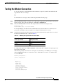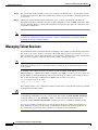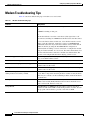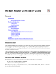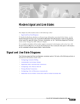
1
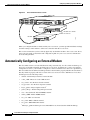
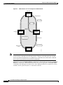
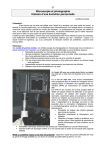
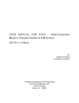
Configuring and Managing External Modems
This chapter describes how to configure externally connected modems. These tasks are presented in the
following main sections:
•
External Modems on Low-End Access Servers
•
Automatically Configuring an External Modem
•
Manually Configuring an External Modem
•
Supporting Dial-In Modems
•
Testing the Modem Connection
•
Managing Telnet Sessions
•
Modem Troubleshooting Tips
•
Checking Other Modem Settings
To identify the hardware platform or software image information associated with a feature, use the
Feature Navigator on Cisco.com to search for information about the feature or refer to the software
release notes for a specific release. For more information, see the “Identifying Supported Platforms”
section in the “Using Cisco IOS Software” chapter.
For a complete description of the modem support commands in this chapter, refer to the Cisco IOS Dial
Technologies Command Reference. To locate documentation of other commands that appear in this
chapter, use the command reference master index or search online.
External Modems on Low-End Access Servers
Some of the Cisco lower-end access servers, such as the Cisco AS2511-RJ shown in Figure 23, have
cable connections to external modems. The asynchronous interfaces and lines are inside the access
server.
Cisco IOS Dial Technologies Configuration Guide
DC-145
Configuring and Managing External Modems
Automatically Configuring an External Modem
Figure 23
Cisco AS2511-RJ Access Server
Cisco AS2511-RJ
9
1
ASYNC
ASYNC
10
2
11
ASYNC
12
3
ASYNC
4
13
ASYNC
14
5
ASYNC
6
15
ASYNC
16
7
ASYNC
8
Modem
Modems are outside
the chassis
14479
Modem
When you configure modems to function with your access server, you must provide initialization strings
and other settings on the modem to tell it how to function with the access server.
This section assumes that you have already physically attached the modem to the access server. If not,
refer to the user guide or installation and configuration guide for your access server for information
about attaching modems.
Automatically Configuring an External Modem
The Cisco IOS software can issue initialization strings automatically, in a file called a modemcap, for
most types of modems externally attached to the access server. A modemcap is a series of parameter
settings that are sent to your modem to configure it to interact with the Cisco device in a specified way.
The Cisco IOS software defines modemcaps that have been found to properly initialize most modems so
that they function properly with Cisco routers and access servers. For Cisco IOS Release 12.2, these
modemcaps have the following names:
•
default—Generic Hayes interface external modem
•
codex_3260—Motorola Codex 3260 external
•
usr_courier—U.S. Robotics Courier external
•
usr_sportster—U.S. Robotics Sportster external
•
hayes_optima—Hayes Optima external1
•
global_village—Global Village Teleport external
•
viva—Viva (Rockwell ACF with MNP) external
•
telebit_t3000—Telebit T3000 external
•
nec_v34—NEC V.34 external
•
nec_v110—NEC V.110 TA external
•
nec_piafs—NEC PIAFS TA external
1
The hayes_optima modemcap is not recommended for use; instead, use the default modemcap.
Cisco IOS Dial Technologies Configuration Guide
DC-146
Configuring and Managing External Modems
Automatically Configuring an External Modem
Enter these modemcap names with the modemcap entry command.
If your modem is not on this list and if you know what modem initialization string you need to use with
it, you can create your own modemcap; see the following procedure “Using the Modem Autoconfigure
Type Modemcap Feature.” To have the Cisco IOS software determine what type of modem you have, use
the modem autoconfigure discovery command to configure it, as described in the procedure “Using the
Modem Autoconfigure Discovery Feature.”
Using the Modem Autoconfigure Type Modemcap Feature
Step 1
Use the modemcap edit command to define your own modemcap entry.
The following example defines modemcap MODEMCAPNAME:
Router(config)# modemcap edit MODEMCAPNAME miscellaneous &FS0=1&D3
Step 2
Apply the modemcap to the modem lines as shown in the following example:
Router# terminal monitor
Router# debug confmodem
Modem Configuration Database debugging is on
Router# configure terminal
Enter configuration commands, one per line. End with CNTL/Z.
Router(config)# line 33 34
Router(config-line)# modem autoconfigure type MODEMCAPNAME
Router(config-line)#
Jan 16 18:12:59.643: TTY34: detection speed (115200) response ---OK--Jan 16 18:12:59.643: TTY34: Modem command: --AT&FS0=1&D3-Jan 16 18:12:59.659: TTY33: detection speed (115200) response ---OK--Jan 16 18:12:59.659: TTY33: Modem command: --AT&FS0=1&D3-Jan 16 18:13:00.227: TTY34: Modem configuration succeeded
Jan 16 18:13:00.227: TTY34: Detected modem speed 115200
Jan 16 18:13:00.227: TTY34: Done with modem configuration
Jan 16 18:13:00.259: TTY33: Modem configuration succeeded
Jan 16 18:13:00.259: TTY33: Detected modem speed 115200
Jan 16 18:13:00.259: TTY33: Done with modem configuration
Using the Modem Autoconfigure Discovery Feature
If you prefer the modem software to use its autoconfigure mechanism to configure the modem, use the
modem autoconfigure discovery command.
The following example shows how to configure modem autoconfigure discovery mode:
Router# terminal monitor
Router# debug confmodem
Modem Configuration Database debugging is on
Router# configure terminal
Enter configuration commands, one per line. End with CNTL/Z.
Router(config)# line 33 34
Router(config-line)# modem autoconfigure discovery
Jan 16 18:16:17.724: TTY33: detection speed (115200) response ---OK--Jan 16 18:16:17.724: TTY33: Modem type is default
Jan 16 18:16:17.724: TTY33: Modem command: --AT&F&C1&D2S0=1H0-Jan 16 18:16:17.728: TTY34: detection speed (115200) response ---OK--Jan 16 18:16:17.728: TTY34: Modem type is default
Jan 16 18:16:17.728: TTY34: Modem command: --AT&F&C1&D2S0=1H0-Jan 16 18:16:18.324: TTY33: Modem configuration succeeded
Cisco IOS Dial Technologies Configuration Guide
DC-147
Configuring and Managing External Modems
Manually Configuring an External Modem
Jan
Jan
Jan
Jan
Jan
16
16
16
16
16
18:16:18.324:
18:16:18.324:
18:16:18.324:
18:16:18.324:
18:16:18.324:
TTY33:
TTY33:
TTY34:
TTY34:
TTY34:
Detected modem speed 115200
Done with modem configuration
Modem configuration succeeded
Detected modem speed 115200
Done with modem configuration
Manually Configuring an External Modem
If you cannot configure your modem automatically, you must configure it manually. This section
describes how to determine and issue the correct initialization string for your modem and how to
configure your modem with it.
Modem command sets vary widely. Although most modems use the Hayes command set (prefixing
commands with at), Hayes-compatible modems do not use identical at command sets.
Refer to the documentation that came with your modem to learn how to examine the current and stored
configuration of the modem that you are using. Generally, you enter at commands such as &v, i4, or *o
to view, inspect, or observe the settings.
Timesaver
You must first create a direct Telnet or connection session to the modem before you can send an
initialization string. You can use AT&F as a basic modem initialization string in most cases. To
establish a direct Telnet session to an external modem, determine the IP address of your LAN
(Ethernet) interface, and then enter a Telnet command to port 2000 + n on the access server, where n
is the line number to which the modem is connected. See the sections “Testing the Modem
Connection” and “Managing Telnet Sessions” for more information about making Telnet
connections.
A sample modem initialization string for a US Robotics Courier modem is as follows:
&b1&h1&r2&c1&d3&m4&k1s0=1
Modem initialization strings enable the following functions:
Note
•
Locks the speed of the modem to the speed of the serial port on the access server
•
Sets hardware flow control (RTS/CTS or request to send/clear to send)
•
Ensures correct data carrier detect (DCD) operation
•
Ensures proper data terminal ready (DTR) interpretation
•
Answers calls on the first ring
Make sure to turn off automatic baud rate detection because the modem speeds must be set to a fixed
value.
The port speed must not change when a session is negotiated with a remote modem. If the speed of the
port on the access server is changed, you must establish a direct Telnet session to the modem and send
an at command so that the modem can learn the new speed.
Cisco IOS Dial Technologies Configuration Guide
DC-148
Configuring and Managing External Modems
Supporting Dial-In Modems
Modems differ in the method that they use to lock the EIA/TIA-232 (serial) port speed. In the modem
documentation, vendors use terms such as port-rate adjust, speed conversion, or buffered mode. Enabling
error correction often puts the modem in the buffered mode. Refer to your modem documentation to
learn how your modem locks speed (check the settings &b, \j, &q, \n, or s-register settings).
RTS and CTS signals must be used between the modem and the access server to control the flow of data.
Incorrectly configuring flow control for software or setting no flow control can result in hung sessions
and loss of data. Modems differ in the method that they use to enable hardware flow control. Refer to
your modem documentation to learn how to enable hardware flow control (check the settings &e, &k,
&h, &r, or s-register).
The modem must use the DCD wire to indicate to the access server when a session has been negotiated
and is established with a remote modem. Most modems use the setting &c1. Refer to your modem
documentation for the DCD settings used with your modem.
The modem must interpret a toggle of the DTR signal as a command to drop any active call and return
to the stored settings. Most modems use the settings &d2 or &d3. Refer to your modem documentation
for the DTR settings used with your modem.
If a modem is used to service incoming calls, it must be configured to answer a call after a specific
number of rings. Most modems use the setting s0=1 to answer the call after one ring. Refer to your
modem documentation for the settings used with your modem.
Supporting Dial-In Modems
The Cisco IOS software supports dial-in modems that use DTR to control the off-hook status of the
telephone line. This feature is supported primarily on old-style modems, especially those in Europe. To
configure the line to support this feature, use the following command in line configuration mode:
Command
Purpose
Router(config-line)# modem callin
Configures a line for a dial-in modem.
Figure 24 illustrates the modem callin command. When a modem dialing line is idle, it has its DTR
signal at a low state and waits for a transition to occur on the data set ready (DSR) input. This transition
causes the line to raise the DTR signal and start watching the CTS signal from the modem. After the
modem raises CTS, the Cisco IOS software creates an EXEC session on the line. If the timeout interval
(set with the modem answer-timeout command) passes before the modem raises the CTS signal, the
line lowers the DTR signal and returns to the idle state.
Cisco IOS Dial Technologies Configuration Guide
DC-149
Configuring and Managing External Modems
Supporting Dial-In Modems
Figure 24
EXEC Creation on a Line Configured for Modem Dial-In
Idle state
DTR low,
watching
CTS
Ring transition
Raise DTR
Lower DTR
Answer
timeout
Hang up
DTR high,
watching
CTS
DTR low
Lower DTR
close connection
Ringing
CTS raised
Create EXEC
CTS lowered
or exit
Ready and active
Note
S1001a
DTR high
The modem callin and modem cts-required line configuration commands are useful for SLIP
operation. These commands ensure that when the line is hung up or the CTS signal drops, the line
reverts from Serial Line Internet Protocol (SLIP) mode to normal interactive mode. These commands
do not work if you put the line in network mode permanently.
Although you can use the modem callin line configuration command with newer modems, the modem
dialin line configuration command described in this section is more appropriate. The modem dialin
command frees up CTS input for hardware flow control. Modern modems do not require the assertion
of DTR to answer a phone line (that is, to take the line off-hook).
Cisco IOS Dial Technologies Configuration Guide
DC-150
Configuring and Managing External Modems
Testing the Modem Connection
Testing the Modem Connection
To test the connection, send the modem the AT command to request its attention. The modem should
respond with “OK.” For example:
at
OK
If the modem does not reply to the at command, perform the following steps:
Step 1
Enter the show users EXEC command and scan the display output. The output should not indicate that
the line is in use. Also verify that the line is configured for modem inout.
Step 2
Enter the show line EXEC command. The output should contain the following two lines:
Modem state: Idle
Modem hardware state: CTS noDSR
DTR RTS
If the output displays “no CTS” for the modem hardware state, the modem is not connected, is not
powered up, is waiting for data, or might not be configured for hardware flow control.
Step 3
Verify the line speed and modem transmission rate. Make sure that the line speed on the access server
matches the transmission rate, as shown in Table 13.
Table 13
Matching Line Speed with Transmission Rate
Modem Transmission Rate
(in bits per second)
Line Speed on the Access Server
(in bits per second)
9600
38400
14400
57600
28800
115200
To verify the line speed, use the show run EXEC command. The line configuration fragment appears at
the tail end of the output.
The following example shows that lines 7 through 9 are transmitting at 115200 bits per second (bps).
Sixteen 28800-kbps modems are connected to a Cisco AS2511-RJ access server via a modem cable.
Router# show run
Building configuration...
Current configuration:
. . .
!
line 1 16
login local
modem InOut
speed 115200
transport input all
flowcontrol hardware
script callback callback
autoselect ppp
autoselect during-login
Cisco IOS Dial Technologies Configuration Guide
DC-151
Configuring and Managing External Modems
Managing Telnet Sessions
Step 4
The speeds of the modem and the access server are likely to be different. If so, switch off the modem,
and then switch it back on. This action should change the speed of the modem to match the speed of the
access server.
Step 5
Check your cabling and the modem configuration (echo or result codes might be off). Enter the
appropriate at modem command to view the modem configuration, or use the at&f command to return
to factory defaults. Refer to your modem documentation to learn the appropriate at command to view
your modem configuration.
Note
See the section “Configuring Cisco Integrated Modems Using Modem Attention Commands” in the
“Configuring and Managing Integrated Modems” chapter for information about modem attention
commands for the Cisco internal modems.
Managing Telnet Sessions
You communicate with an external modem by establishing a direct Telnet session from the asynchronous
line on the access server, which is connected to the modem. This process is also referred to as reverse
Telnet. Performing a reverse Telnet means that you are initiating a Telnet session out the asynchronous
line, instead of accepting a connection into the line (called a forward connection).
Note
Before attempting to allow inbound connections, make sure that you close all open connections to
the modems attached to the access server. If you have a modem port in use, the modem will not accept
a call properly.
To establish a direct Telnet session to an external modem, determine the IP address of your LAN
(Ethernet) interface, and then enter a Telnet command to port 2000 + n on the access server, where n is
the line number to which the modem is connected. For example, to connect to the modem attached to
line 1, enter the following command from an EXEC session on the access server:
Router# telnet 172.16.1.10 2001
Trying 172.16.1.10, 2001 ... Open
This example enables you to communicate with the modem on line 1 using the AT (attention) command
set defined by the modem vendor.
Timesaver
Use the ip host configuration command to simplify direct Telnet sessions with modems. The ip host
command maps an IP address of a port to a device name. For example, the modem1 2001 172.16.1.10
command enables you to enter modem1 to initiate a connection with the modem, instead of
repeatedly entering telnet 172.16.1.10 2001 each time you want to communicate with the modem.
You can also configure asynchronous rotary line queueing, which places Telnet login requests in a
queue when lines are busy. See the section “Configuring Asynchronous Rotary Line Queueing” in
the “Configuring Asynchronous Lines and Interfaces” chapter for more information.
Cisco IOS Dial Technologies Configuration Guide
DC-152
Configuring and Managing External Modems
Managing Telnet Sessions
Suspending Telnet Sessions:
When you are connected to an external modem, the direct Telnet session must be terminated before the
line can accept incoming calls. If you do not terminate the session, it will be indicated in the output of
the show users command and will return a modem state of ready if the line is still in use. If the line is
no longer in use, the output of the show line value command will return a state of idle. Terminating the
Telnet session requires first suspending it, then disconnecting it.
To suspend a Telnet session, perform the following steps:
Step 1
Enter Ctrl-Shift-6 x to suspend the Telnet session:
- suspend keystroke Router#
Note
Step 2
Ensure that you can reliably issue the escape sequence to suspend a Telnet session. Some
terminal emulation packages have difficulty sending the Ctrl-Shift-6 x sequence. Refer to
your terminal emulation documentation for more information about escape sequences.
Enter the where EXEC command to check the connection numbers of open sessions:
Router# where
Conn Host
* 1 172.16.1.10
2 172.16.1.11
Step 3
Address
172.16.1.10
172.16.1.11
Byte
0
0
Idle Conn Name
0 172.16.1.10
12 modem2
When you have suspended a session with one modem, you can connect to another modem and suspend it:
Router# telnet modem2
Trying modem2 (172.16.1.11, 2002) ... Open
- suspend keystroke Router#
Step 4
To disconnect (completely close) a Telnet session, enter the disconnect EXEC command:
Router#
Closing
Router#
Closing
Router#
disconnect
connection
disconnect
connection
line 1
to 172.16.1.10 [confirm] y
line 2
to 172.16.1.11 [confirm] y
Cisco IOS Dial Technologies Configuration Guide
DC-153
Configuring and Managing External Modems
Modem Troubleshooting Tips
Modem Troubleshooting Tips
Table 14 contains troubleshooting tips on modem access and control.
Table 14
Modem Troubleshooting Tips
Problem
Likely Cause
Connection refused.
Someone already has a connection to that port.
or
an EXEC is running on that port.
or
The modem failed to lower the carrier detect (CD) signal after a call
disconnected, resulting in an EXEC that remained active after disconnect.
To force the line back into an idle state, clear the line from the console
and try again. If it still fails, ensure that you have set modem inout
command for that line. If you don't have modem control, either turn off
EXEC on the line (by using the exec-timeout line configuration
command) before making a reverse connection or configure the modem
using an external terminal. As a last resort, disconnect the modem, clear
the line, make the Telnet connection, and then attach the modem. The
prevents a misconfigured modem from denying you line access.
Connection appears to hang.
Try entering “^U” (clear line), “^Q” (XON), and press Return a few times
to try to establish terminal control.
EXEC does not come up; autoselect is on.
Press Return to enter EXEC.
Modem does not hang up after entering quit.
The modem is not receiving DTR information, or you have not set up
modem control on the router.
Interrupts another user session when you dial in.
The modem is not dropping CD on disconnect, or you have not set up
modem control on the router.
Connection hangs after entering “+++” on the
dialing modem, followed by an ATO.
The answering modem saw and interpreted the “+++” when it was echoed
to you. This is a bug in the answering modem, common to many modems.
There may be a switch to work around this problem; check the modem’s
documentation.
Losing data.
You may have Hardware Flow Control only on for either the router’s line
(DTE) or the modem (DCE). Hardware Flow Control should be on for
both or off for both, but not for only one.
Using MDCE.
Turn MDCE into an MMOD by moving pin 6 to pin 8 because most
modems use CD and not DSR to indicate the presence of carrier. You can
also program some modems to provide carrier info via DSR.
Cisco IOS Dial Technologies Configuration Guide
DC-154
Configuring and Managing External Modems
Checking Other Modem Settings
Checking Other Modem Settings
This section defines other settings that might be needed or desirable, depending on your modem.
Error correction can be negotiated between two modems to ensure a reliable data link. Error correction
standards include Link Access Procedure for Modems (LAPM) and MNP4. V.42 error correction allows
either LAPM or MNP4 error correction to be negotiated. Modems differ in the way they enable error
correction. Refer to your modem documentation for the error correction methods used with your modem.
Data compression can be negotiated between two modems to allow for greater data throughput. Data compression standards include V.42bis and MNP5. Modems differ in the way they enable data compression.
Refer to your modem documentation for the data compression settings used with your modem.
Cisco IOS Dial Technologies Configuration Guide
DC-155
Configuring and Managing External Modems
Checking Other Modem Settings
Cisco IOS Dial Technologies Configuration Guide
DC-156