1
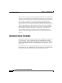
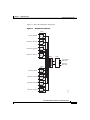
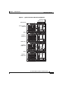
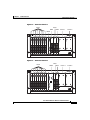
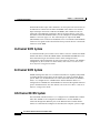
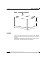
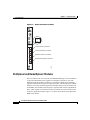
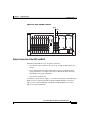
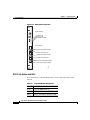
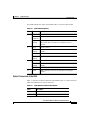
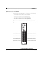
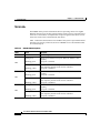
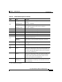
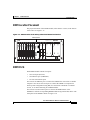
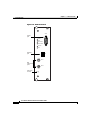
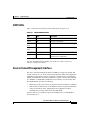
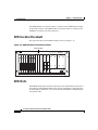
C H A P T E R
1
Product Overview
This chapter describes the Cisco Metro 1500 series metropolitan area network
(MAN) dense wavelength division multiplexing (DWDM) system, and includes
the following sections:
•
Product Description, page 1-1
•
Communication Channels, page 1-2
•
Chassis, page 1-11
•
System Modules, page 1-15
Product Description
The Cisco Metro 1500 series system is a high-performance, wavelength division
multiplexer that provides bidirectional data communication. It is designed for
communication over optical links in which different devices or applications are
communicating over multiple fibers. Using wavelength conversion, several
devices can communicate while being connected over one duplex fiber or two
single fibers.
The Cisco Metro 1500 series system expands the distance and application
capabilities of existing local area networks (LANs), metropolitan area networks
(MANs), and storage area networks (SANs). It is protocol-independent and can
support virtually any fiber-optic device.
Cisco Metro 1500 Series Hardware Installation Guide
78-10588-03
1-1
Chapter 1
Product Overview
Communication Channels
The Cisco Metro 1500 series operates using the International Telecommunication
Union (ITU) wavelength grid of 200-GHz channel spacing. It receives the signal
from the local device and converts it to the desired wavelength. Only single-mode
fibers (remote or trunk fibers) are used for multiplexed data transmission.
The Cisco Metro 1500 series system provides communication within a broad
range of data rates, up to 2.488 Gbps, and within a guaranteed optical budget. The
system is transparent to any data communication protocol except wavelength
channel modules (WCMs) with clock recovery. For more details on data rates,
optical budgets, and supported protocols, see Appendix A, “Specifications.”
The Cisco Metro 1500 series system also provides monitoring and service
functions such as loss of light and bit-rate control, as well as local and remote
loopback.
Communication Channels
DWDM technology allows different channels to be combined for transportation
over one fiber pair. A pair of multiplexer (MUX) and demultiplexer (DMX)
modules assemble the channels into four groups of up to eight channels. The band
splitter module (BSM) assembles and disassembles the four groups for the two
remote fibers.
The optional remote switch module (RSM) provides line protection to the system.
If the working line fails, the RSM routes the combined service automatically to a
backup line. If used, the RSM is installed only in the primary chassis.
Cisco Metro 1500 Series Hardware Installation Guide
1-2
78-10588-03
Chapter 1
Product Overview
Communication Channels
Figure 1-1 shows the multiplexer architecture.
Figure 1-1
Multiplexer Architecture
MUX
CH1
Primary chassis
CH8
CH9
Extension chassis A
CH16
CH17
Extension chassis B
CH24
CH25
Extension chassis C
CH32
BSM
RSM
Transmission
fiber lines
Receiving
fiber lines
DMX
CH1
Primary chassis
CH8
CH9
Extension chassis A
CH16
CH17
Extension chassis B
CH24
Extension chassis C
CH32
39354
CH25
Cisco Metro 1500 Series Hardware Installation Guide
78-10588-03
1-3
Chapter 1
Product Overview
Communication Channels
Primary and Extension Chassis
The Cisco Metro 1500 series system has a modular structure so you can expand
the system while it is in use. Adding or removing channels does not affect the
other working channels. Figure 1-2 shows a typical Cisco Metro 1500 series
system configuration containing a primary chassis and three extension chassis.
Cisco Metro 1500 Series Hardware Installation Guide
1-4
78-10588-03
Chapter 1
Product Overview
Communication Channels
Figure 1-2
Typical Cisco Metro 1500 Series Configuration
Ethernet cables
Ethernet hub
DC Input
NEMI master
Uplink
6x
5x
4x
3x
METRO 1500 SERIES
2x
1x
OK FAIL
POWER
Power
MUX
DMX
1-8(32)
1-8(32)
on
Serial
On/Err
Loop
L/R
L/T
R/R
R/T
Primary chassis:
WCM 1-8
On/Err
Loop
L/R
L/T
R/R
R/T
On/Err
Loop
L/R
L/T
R/R
R/T
On/Err
Loop
L/R
L/T
R/R
R/T
On/Err
Loop
L/R
L/T
R/R
R/T
On/Err
Loop
L/R
L/T
R/R
R/T
On/Err
Loop
L/R
L/T
R/R
R/T
On/Err
Loop
L/R
L/T
R/R
R/T
Receive
Link
nc
M1
L/R
L/R
L/R
L/R
L/R
L/R
L/R
L/T
L/T
L/T
L/T
L/T
L/T
L/T
L/T
R/R
R/R
R/R
R/R
R/R
R/R
R/R
R/R
nc
D1
8
8
7
7
6
BUS 1
6
5
5
4
4
3
BUS 2
3
2
R/T
R/T
R/T
R/T
R/T
R/T
R/T
Power
on
Power
Error
Err.Int.BUS
Err.Ext.BUS
Net
L/R
OK FAIL
FAN
R/T
2
1
1
0
I
DEMI
METRO 1500 SERIES
OK FAIL
POWER
Power
MUX
DMX
1-8(32)
1-8(32)
on
Chassis A:
WCM 9-16
On/Err
Loop
L/R
L/T
R/R
R/T
On/Err
Loop
L/R
L/T
R/R
R/T
On/Err
Loop
L/R
L/T
R/R
R/T
On/Err
Loop
L/R
L/T
R/R
R/T
On/Err
Loop
L/R
L/T
R/R
R/T
On/Err
Loop
L/R
L/T
R/R
R/T
On/Err
Loop
L/R
L/T
R/R
R/T
On/Err
Loop
L/R
L/T
R/R
R/T
OK FAIL
FAN
Power
on
On
Err
nc
D1
nc
M1
8
8
L/R
L/R
L/R
L/R
L/R
L/R
L/R
L/R
L/T
L/T
L/T
L/T
L/T
L/T
L/T
L/T
R/R
R/R
R/R
R/R
R/R
R/R
R/R
R/R
3
R/T
R/T
R/T
R/T
R/T
R/T
R/T
R/T
1
7
7
BUS 1
6
6
5
5
BUS 2
4
4
3
2
2
1
0
I
NEMI slave
METRO 1500 SERIES
OK FAIL
POWER
Power
MUX
DMX
1-8(32)
1-8(32)
on
Serial
On/Err
Loop
L/R
L/T
R/R
R/T
Chassis B:
WCM 17-24
On/Err
Loop
L/R
L/T
R/R
R/T
On/Err
Loop
L/R
L/T
R/R
R/T
On/Err
Loop
L/R
L/T
R/R
R/T
On/Err
Loop
L/R
L/T
R/R
R/T
On/Err
Loop
L/R
L/T
R/R
R/T
On/Err
Loop
L/R
L/T
R/R
R/T
On/Err
Loop
L/R
L/T
R/R
R/T
OK FAIL
FAN
Power
on
Power
Error
Err.Int.BUS
Err.Ext.BUS
Receive
Link
nc
M1
nc
D1
Net
L/R
L/R
L/R
L/R
L/R
L/R
L/R
L/R
L/T
L/T
L/T
L/T
L/T
L/T
L/T
L/T
R/R
R/R
R/R
R/R
R/R
R/R
R/R
R/R
R/T
R/T
R/T
R/T
R/T
R/T
R/T
R/T
8
8
7
BUS 1
7
6
6
5
5
4
BUS 2
4
3
3
2
2
1
1
0
I
DEMI
METRO 1500 SERIES
OK FAIL
POWER
Power
MUX
DMX
1-8(32)
1-8(32)
on
Chassis C:
WCM 25-32
On/Err
Loop
L/R
L/T
R/R
R/T
On/Err
Loop
L/R
L/T
R/R
R/T
On/Err
Loop
L/R
L/T
R/R
R/T
On/Err
Loop
L/R
L/T
R/R
R/T
On/Err
Loop
L/R
L/T
R/R
R/T
On/Err
Loop
L/R
L/T
R/R
R/T
On/Err
Loop
L/R
L/T
R/R
R/T
On/Err
Loop
L/R
L/T
R/R
R/T
OK FAIL
FAN
Power
on
On
Err
nc
M1
nc
D1
8
L/R
L/R
L/R
L/R
L/R
L/R
L/R
L/R
L/T
L/T
L/T
L/T
L/T
L/T
L/T
L/T
R/R
R/R
R/R
R/R
R/R
R/R
R/R
R/R
3
R/T
R/T
R/T
R/T
R/T
R/T
R/T
R/T
1
7
8
7
BUS 1
6
5
BUS 2
6
5
4
4
3
2
2
1
0
50317
I
External bus cable
Cisco Metro 1500 Series Hardware Installation Guide
78-10588-03
1-5
Chapter 1
Product Overview
Communication Channels
Expansion Modules
The Cisco Metro 1500 series system requires two identical WCMs to complete a
full communications link, one at each end of the link. Each system unit includes
a primary chassis (see Figure 1-3) that holds up to eight WCMs. The WCMs
transport up to eight independent channels.
Figure 1-3
Primary Chassis
MUX
WCM
RSM
DMX
NEMI
Power 1
METRO 1500 SERIES
Power 2
OK FAIL
POWER
Power
MUX
DMX
1-8(32)
1-8(32)
on
Serial
On/Err
Loop
L/R
L/T
R/R
R/T
On/Err
Loop
L/R
L/T
R/R
R/T
On/Err
Loop
L/R
L/T
R/R
R/T
On/Err
Loop
L/R
L/T
R/R
R/T
On/Err
Loop
L/R
L/T
R/R
R/T
On/Err
Loop
L/R
L/T
R/R
R/T
On/Err
Loop
L/R
L/T
R/R
R/T
On/Err On
Loop A
L/R
L/T
R/R
R/T
Lk
B
LkA
LkB
Auto
OK FAIL
FAN
Power
on
Power
Error
Err.Int.BUS
Err.Ext.BUS
Receive
Link
nc
M1
nc
D1
Net
L/R
L/R
L/R
L/R
L/R
L/R
L/R
L/R
L/T
L/T
L/T
L/T
L/T
L/T
L/T
L/T
8
8
A/T
A/R
7
7
BUS 1
6
6
5
5
B/T
B/R
4
4
R/R
R/R
R/R
R/R
R/R
R/R
R/R
R/R
R/T
R/T
R/T
R/T
R/T
R/T
R/T
R/T
BUS 2
M
D
3
3
2
2
1
1
0
39943
I
The Cisco Metro 1500 series system can be expanded by adding more WCMs.
Adding extension chassis A, B, and C (Figure 1-4 to Figure 1-6) at both ends of
the communications link upgrades the system to transport a total of 32
independent channels. A network element management interface (NEMI) can
control up to two chassis and up to four NEMIs can be combined through an
Ethernet hub or switch to appear as a single system as seen by a Network
Management System (NMS). We recommend that you initially install the primary
chassis and extension chassis A, which holds the BSM, to avoid service
interruption while upgrading the unit to more than eight channels. The primary
chassis and the extension chassis are each equipped with two fully redundant
load-sharing, hot-swappable power supply modules (PSMs), as shown in
Figure 1-3 to Figure 1-6.
Cisco Metro 1500 Series Hardware Installation Guide
1-6
78-10588-03
Chapter 1
Product Overview
Communication Channels
Figure 1-4
Extension Chassis A
WCM
MUX
DMX
BSM
Power 1
Power 2
DEMI
METRO 1500 SERIES
POWER
Power
BSM
MUX
DMX
1-8(32)
1-8(32)
on
On/Err
Loop
L/R
L/T
R/R
R/T
On/Err
Loop
L/R
L/T
R/R
R/T
On/Err
Loop
L/R
L/T
R/R
R/T
On/Err
Loop
L/R
L/T
R/R
R/T
On/Err
Loop
L/R
L/T
R/R
R/T
On/Err
Loop
L/R
L/T
R/R
R/T
On/Err
Loop
L/R
L/T
R/R
R/T
On/Err
Loop
L/R
L/T
R/R
R/T
L/R
L/R
L/R
L/R
L/R
L/R
L/R
L/R
L/T
L/T
L/T
L/T
L/T
L/T
L/T
L/T
FAN
Power
on
On
Err
M
D
M1
D1
M2
D2
M3
D3
nc
M1
nc
D1
8
8
7
7
BUS 1
BUS 2
R/R
R/R
R/T
R/R
R/T
R/R
R/T
R/R
R/T
R/R
R/T
R/R
R/T
R/R
R/T
M4
R/T
6
6
5
5
4
4
3
3
2
D4
2
1
1
0
39340
I
Figure 1-5
Extension Chassis B
MUX
WCM
DMX
NEMI
Power 1
Power 2
METRO 1500 SERIES
OK FAIL
POWER
Power
MUX
DMX
1-8(32)
1-8(32)
on
Serial
On/Err
Loop
L/R
L/T
R/R
R/T
On/Err
Loop
L/R
L/T
R/R
R/T
On/Err
Loop
L/R
L/T
R/R
R/T
On/Err
Loop
L/R
L/T
R/R
R/T
On/Err
Loop
L/R
L/T
R/R
R/T
On/Err
Loop
L/R
L/T
R/R
R/T
On/Err
Loop
L/R
L/T
R/R
R/T
On/Err
Loop
L/R
L/T
R/R
R/T
OK FAIL
FAN
Power
on
Power
Error
Err.Int.BUS
Err.Ext.BUS
Receive
Link
nc
M1
nc
D1
Net
L/R
L/R
L/R
L/R
L/R
L/R
L/R
L/R
L/T
L/T
L/T
L/T
L/T
L/T
L/T
L/T
R/R
R/R
R/R
R/R
R/R
R/R
R/R
R/R
R/T
R/T
R/T
R/T
R/T
R/T
R/T
R/T
8
8
7
7
BUS 1
6
6
5
5
4
4
BUS 2
3
3
2
2
1
1
0
33941
I
Cisco Metro 1500 Series Hardware Installation Guide
78-10588-03
1-7
Chapter 1
Product Overview
Communication Channels
Figure 1-6
Extension Chassis C
DMX
WCM
MUX
DEMI
Power 1
METRO 1500 SERIES
Power 2
OK FAIL
POWER
Power
MUX
DMX
1-8(32)
1-8(32)
on
On/Err
Loop
L/R
L/T
R/R
R/T
On/Err
Loop
L/R
L/T
R/R
R/T
On/Err
Loop
L/R
L/T
R/R
R/T
On/Err
Loop
L/R
L/T
R/R
R/T
On/Err
Loop
L/R
L/T
R/R
R/T
On/Err
Loop
L/R
L/T
R/R
R/T
On/Err
Loop
L/R
L/T
R/R
R/T
On/Err
Loop
L/R
L/T
R/R
R/T
L/R
L/R
L/R
L/R
L/R
L/R
L/R
L/T
L/T
L/T
L/T
L/T
L/T
L/T
L/T
R/R
R/R
R/R
R/R
R/R
R/R
R/R
R/R
Power
on
On
Err
nc
M1
L/R
OK FAIL
FAN
nc
D1
8
8
7
7
BUS 1
6
6
5
5
BUS 2
4
4
3
3
2
2
R/T
R/T
R/T
R/T
R/T
R/T
R/T
R/T
1
1
0
39942
I
Figure 1-7 shows the rear view of the primary chassis and extension chassis.
Cisco Metro 1500 Series Hardware Installation Guide
1-8
78-10588-03
Chapter 1
Product Overview
Communication Channels
Figure 1-7
Rear View of the Chassis
Fan module
Fuse 2
Voltage:
Max. Current:
Power Consumption:
Fuse:
Power 1
Fuse 1
115/230 V 50/60 Hz
2.5 A
max. 100W
2x T2.5A / 250V
For continued protection against risk of fire replace
only with same type and ratings of fuse.
For proper selection of power supply cord refer to
instruction manual.
Always remove both
power cords when disMade in Germany
connecting from power
March 1998
source 1.
FSP - II/1/WDM
Manufactured: March 2000
BASE-F2Z-D2-A1-ZZ
Model:
Serial-No.: AD-23-W349
ADVA AG, 98617 Meiningen, Jerusalemer Straße 13, Germany
Only valid if all modules and/or blind panels are in.place
39353
Power 2
!
AC power
connectors
Identification
plate
Fuse
holders
Instructions for
power supply
Certification
marks
Each chassis is delivered with one to eight WCMs, according to the configuration
ordered. Each WCM provides the conversion of the local or remote channels to
their respective wavelengths. All modules are hot-swappable and can be repaired
or upgraded while the other WCMs are in use. WCMs support a wide range of data
rates. For more information on data rates, optical budgets, and supported
protocols, see Appendix A, “Specifications,” and Appendix E, “Unit Maintenance
and Network Record.”
The RSM is available as an option. The RSM provides the system with 1+1 line
protection and is installed in the primary chassis only. (See Figure 1-3).
The primary chassis and extension chassis B also include the network element
management interface (NEMI) module. Extension chassis A and C includes an
optional device element management interface (DEMI) module. For information
on the NEMI and DEMI, refer to the Cisco Metro 1500 Series Software
Configuration Guide.
Cisco Metro 1500 Series Hardware Installation Guide
78-10588-03
1-9
Chapter 1
Product Overview
Communication Channels
Each WCM has fiber-optic cables attached to its front panel. The remote lines of
each WCM are connected to the MUX and DMX of the chassis. The common
input and output connections of MUXs and DMXs (M1 to M4/D1 to D4) are
connected to the BSM (M1 to M4/D1 to D4) in extension chassis A. For more
information on the MUX/DMX modules, see the “Multiplexer and Demultiplexer
Modules” section on page 1-22. The common input or output of the BSM
(MUX/DMX) can be connected to the RSM receiver or transmitter (MUX/DMX)
connector. The signals of the remote link are then present at the line A and line B
connectors of the RSM.
16-Channel WCM System
A 16 channel WCM system consists of two chassis. Chassis 1 includes the NEMI
module and chassis 2 holds the DEMI module. Both NEMI and DEMI have to be
interconnected using an external bus cable to allow management and
configuration control information to pass between the two chassis. The NEMI is
configurable by the customer. For more details, refer to the Cisco Metro 1500
Series Software Configuration Guide.
32-Channel WCM System
NEMIs exchange their data over a connection and the two originally independent
16 channel WCM systems appear to the outside as a single 32-channel WCM
system. When two 16-channel units are connected in this manner, the NEMI in
chassis 1 is configured to be a NEMI-master and the NEMI in chassis 3 is
configured to be a NEMI-slave. Both NEMIs are connected through their Ethernet
ports to the Ethernet hub. For more details, refer to the Cisco Metro 1500 Series
Software Configuration Guide.
128-Channel ESCON System
The first NEMI, installed in chassis 1, is configured to be a NEMI-master and the
other three NEMIs are all configured as NEMI-slaves. All four NEMIs are
connected through their Ethernet ports to the Ethernet hub. Provided that the
frames are connected and configured as described, the complete system of eight
Cisco Metro 1500 Series Hardware Installation Guide
1-10
78-10588-03
Chapter 1
Product Overview
Chassis
frames constitutes a single unified network element with a unique Ethernet
address. For more details, refer to the Cisco Metro 1500 Series Software
Configuration Guide.
Chassis
Each chassis of the Cisco Metro 1500 series can be mounted in a 19-inch cabinet
or in open racks. Each chassis requires five rack units. The chassis houses all of
the system modules required to achieve the optical communications link.
This section describes the following chassis components:
•
Dimensions
•
Labeling
•
Airflow System
•
Power Supply Module
Dimensions
The housing is modular in accordance with DIN specification 41494 part 5. The
construction comprises two aluminum sides and four aluminum cross extrusions.
Standard features also include sheet-steel covers and die-cast aluminum cover
extrusions. All covers are uncoated aluminum; cross extrusions, side extrusions,
and handles are textured powder-coated. Figure 1-8 shows the dimensions of
the chassis.
Cisco Metro 1500 Series Hardware Installation Guide
78-10588-03
1-11
Chapter 1
Product Overview
Chassis
Figure 1-8
Outer Dimensions of the Housing
440 mm
482 mm
305 mm
32270
222 mm
Labeling
A label at the back of the unit identifies the system. Each WCM, RSM, and NEMI
have unique serial numbers and specification codes printed on the front panels of
the modules.
WCMs are labeled with alphanumeric and pictographic descriptions of their main
properties. Table 1-1 provides descriptions of the WCM labels.
Cisco Metro 1500 Series Hardware Installation Guide
1-12
78-10588-03
Chapter 1
Product Overview
Chassis
Table 1-1
WCM Labels
Main Properties
Specification
WCM with clock recovery. The clock
recovery is fixed to a single frequency as
indicated below the symbol.
622 Mbps
WCM with clock recovery. The clock
recovery can be set to three frequencies.
These frequencies are shown above and
below the symbol.
200 Mbps
125, 155 Mbps
1250 Mbps
Transparent WCM without clock
recovery ranging from 100 to 1250 Mbps.
100 Mbps
Local port description of WCM. Fiber
type is multimode and the
communication wavelength is 1310 nm.
Remote port description of WCM. Fiber
type is single-mode and the
communication wavelength is 1550 nm.
TDM4E with clock recovery. The clock
recovery is fixed to a single frequency as
indicated below the symbol.
4x200 Mbps
Cisco Metro 1500 Series Hardware Installation Guide
78-10588-03
1-13
Chapter 1
Product Overview
Chassis
Airflow System
The airflow system includes an air intake at the bottom front side of the chassis
and a fan module with two fans at the rear of the chassis. Two redundant power
supplies power the fan module. The chassis internal air temperature controls the
rotational speed of the fans.
The state of the fan module can either be observed through the NEMI-master or
it can be read off the fan LEDs at the front side of the chassis. A green light
indicates that everything is in working order. A red light signals that either a fan
or a fan power supply is not working properly, which does not necessarily
endanger the functioning of the air flow system because there are backup fans and
fan power supplies. Refer to the Cisco Metro 1500 Series Software Configuration
Guide for more information about fan observation using the NEMI-master. The
ocmstate-f provides information on the fans.
You can check the fan module status on the display panel at the front of the chassis
and through the NEMI. For more information about using the NEMI to check the
fan status, refer to the Cisco Metro 1500 Series Software Configuration Guide.
Caution
The fan system can only be replaced by Cisco-trained and -certified
technicians.
Power Supply Module
The Cisco Metro 1500 series system provides high reliability in data and
telecommunication applications because it has two identical, fully redundant
power supplies. Each power supply can take over the power needs of the entire
system. These power supplies provide 5V at 30A to the system, and full
input-to-output, input-to-case, and output-to-output isolation. For detailed
information on the power supply and how to replace it, see the “Determining
Power Supply Status” section on page 3-23.
The state of the PSMs can either be observed through the NEMI-Master or it can
be read off the LEDs at the front side of the frame. If both PSMs are working the
green or red power LED is lit, otherwise there is no light at all.
Cisco Metro 1500 Series Hardware Installation Guide
1-14
78-10588-03
Chapter 1
Product Overview
System Modules
System Modules
The Cisco Metro 1500 series system is a modular system, in which modules can
be added or exchanged during operation. You can adjust the system unit to meet
your application requirements. Purchasing a chassis that is not fully populated
with modules allows you to upgrade the system at a later time.
This section describes the following system modules:
Note
•
Wavelength Channel Modules
•
Multiplexer and Demultiplexer Modules
•
Band Splitter Module
•
Remote Switch Module
•
TDM4E Wavelength Channel Modules
The network element management interface (NEMI) and the device
element management interface (DEMI) are described in the Cisco
Metro 1500 Series Software Configuration Guide.
The Cisco Metro 1500 series system uses the technology of Dense Wavelength
Division Multiplexing (DWDM) to optimize usage of available optical fibers.
WCMs convert the local optical signals to separate wavelengths of the ITU-T grid
necessary for DWDM. The MUX is a passive high performance module which
integrates up to eight optical signals into one wavelength band for transportation
through the BSM on one single-mode fiber (Figure 2-13).
The DMX receives the wavelength band from the corresponding MUX at the
remote end of the link via the BSM. In the DMX, the wavelength band is split into
separate wavelength channels that are transferred to the WCMs for reconversion
into the customer application signal as shown in Figure 2-13.
Cisco Metro 1500 Series Hardware Installation Guide
78-10588-03
1-15
Chapter 1
Product Overview
System Modules
Wavelength Channel Modules
Table 1-2 lists the seven WCMs that are available for the Cisco Metro 1500 series
system, their part numbers, and their maximum remote receiver (R/R) input power
in decibels per milliwatt (dBm).
Table 1-2
Available WCMs
WCM
Part Number
Maximum R/R1 Input
Power
Low-speed transparent
with 100 to 200 Mbps
WCM/LS-T
-5 dBm2
High-speed transparent
with 100 to 1250 Mbps
WCM/HS-T
-7 dBm
High-speed
with 622-Mbps clock
WCM/HS-FC622
-7 dBm
High-speed
with 1062-Mbps clock
for coupling link
WCM/HS-FC1062-CL
-7 dBm
High-speed
with 1062- or
1250-Mbps clock
WCM/HS-MC1062/1250 -7 dBm
2.488 Gbps
WCM-FC2488
-8 dBm
1. R/R = remote receiver
2. dBm = decibels referenced to 1 mW — the standard unit of normalized power level used in optics,
where 0 dBm =1 mW, +10 dBm =10 mW.
WCMs are used in pairs. Adding a channel to a communication link requires
adding WCMs of the same type and channel number at both ends of the link. The
available WCM types are either data rate transparent or they have clock recovery
through a fixed or a settable multiclock.
For reasons of laser safety requirements, the WCM is equipped with an automatic
laser shutdown (ALS), which reduces the optical output power of the remote
transmitter whenever a remote link is broken.
Cisco Metro 1500 Series Hardware Installation Guide
1-16
78-10588-03
Chapter 1
Product Overview
System Modules
The status of receivers and transmitters can be observed locally with SNMP-based
network management tools. In addition, the front panel LEDs provide information
on the operating status. Refer to the Cisco Metro 1500 Series Software
Configuration Guide for more information about this feature.
For service purposes, data can be looped. The loop function is switchable using
the network management tools. A local loop connects the electrical output of the
local optical receiver with the electrical input of the local optical transmitter. This
loop enables a test of the local transmission lines, the local receiver, and the local
transmitter. Locally arriving data is directly sent back. A remote loop connects the
electrical output of the optical receiver at the remote system to the electrical input
of the optical transmitter, so that the data sent to the remote system is directly
retransmitted to the local system. This loop enables a test of the remote
transmission lines, the MUX/ DMX pair, the remote receiver and remote
transmitter pair, and the remote system.
Data Rate Transparent WCMs
The following transparent WCMs are available:
•
Low-speed transparent WCM that supports data rates of 100 to 200 Mbps.
•
High-speed transparent WCM that supports data rates of 100 to 1250 Mbps.
These WCMs are protocol-transparent, and they support their data rates within a
guaranteed optical budget. Locally received optical data enters the local receiver
and is electrically transferred to the remote transceiver. It transmits this data in
optical form at a certain ITU wavelength into the MUX, which sends the data to
the system at the other side of the link. There, the optical data enters first the DMX
and then the remote receiver of the system. The data then is electrically
transmitted to the local transmitter, which delivers the optical data.
Remotely received optical data from the paired WCMs enters through the DMX
into the remote receiver at a specific ITU wavelength. The data is then electrically
transmitted to the local transmitter, which delivers the optical data.
You can check the status of receivers and transmitters using the front panel LEDs
or with SNMP-based network management tools. For more information on the
available network management tools, refer to the Cisco Metro 1500 Series
Software Configuration Guide.
Cisco Metro 1500 Series Hardware Installation Guide
78-10588-03
1-17
Chapter 1
Product Overview
System Modules
Data Rate Transparent Front Panel LEDs
The WCM LEDs provide information about its operating status. Table 1-3
describes the LEDs.
Table 1-3
Transparent WCM LED Descriptions
Label
Color1
Description
On/Err
Green
Power is on. No software or hardware errors are detected.
Red
A hardware or software error was detected or the
initialization is in progress (during system startup only).
Red
blinking
WCM is in manual setting mode (not shown in case of
error).
Loop
Orange
A remote and/or a local loop is established.
L/R
Green
Data is received from the local port.
L/T
Green
Data is transmitted to the local port.
R/R
Green
Data is received from the remote end of the link.
R/T
Green
Data is transmitted to the remote end of the link.
Green
blinking
WCM is in ALS mode; LED blinks once every 10 seconds.
1. Any other state than the ones listed indicates a possible failure in the local system.
WCMs with Fixed Clock Recovery
The following transparent WCMs are available with fixed clock recovery:
Note
•
High-speed transparent WCM that supports data rates of 622 Mbps
•
High-speed transparent WCM with 1062-Mbps clock for coupling link
•
WCM that supports 2.488 Gbps
•
WCM with 850-nm multiclock
WCMs with settable clock recovery are also available. See the
“WCMs with Settable Clock Recovery” section on page 1-20.
Cisco Metro 1500 Series Hardware Installation Guide
1-18
78-10588-03
Chapter 1
Product Overview
System Modules
Only signals with the designated data rate can be transmitted within a guaranteed
optical budget.
Clock Recovery Front Panel LEDs
The WCM LEDs provide information about its operating status. Table 1-4
describes the LEDs.
Table 1-4
Clock Recovery WCM LED Descriptions
Label
Color1
Description
On/Err
Green
Power is on. No software or hardware errors are detected.
Red
A hardware or software error was detected or the
initialization is in progress (during system startup only).
Red
blinking
WCM is in manual setting mode (not shown in case of
error).
Loop
Orange
A remote and/or a local loop is established.
L/R
Green
Data is received from a local port and the data rate matches
the clock frequency.
Yellow
Data is received from a local port but the data rate does not
match the clock recovery frequency.
L/T
Green
Data is transmitted to a local port.
R/R
Green
Data is received from the remote end of the link.
R/T
Green
Data is transmitted to the remote end of the link.
Green
blinking
WCM is in ALS mode; LED blinks once every 10 seconds.
Off
Data stream is interrupted because the clock frequency
does not match the current data rate.
1. Any other state than the ones listed indicates a possible failure in the local system.
Locally received optical data enters the local receiver and is electrically
transferred to the remote transmitter using clock-recovery. The clock recovery
locks onto the edges of the data signal and restores the signal to the chosen data
transmission frequency. The remote transmitter transmits the data in optical form
at a certain ITU wavelength to the MUX.
Cisco Metro 1500 Series Hardware Installation Guide
78-10588-03
1-19
Chapter 1
Product Overview
System Modules
Optical data that is sent by the module on the remote side enters the remote
receiver of the local system through the DMX. The data is then electrically
transmitted to the local transmitter, which delivers the optical data.
WCMs with Settable Clock Recovery
The following transparent WCMs are available with settable clock recovery:
•
High-speed WCM with 1062-Mbps clock
•
High-speed WCM with 1250-Mbps clock
•
Low-speed WCM with multiclock (WCM/LS-MC)
•
High-speed WCM with low-speed multiclock (WCM/HS-LS-MC)
•
High-speed WCM with 1062.5- or 1250-Mbit/s clock
(WCM/HS-MC1062/1250). The maximum remote receiver (R/R) input
power for this WCM is -7 dBm.
These WCMs are similar to the WCMs with clock recovery with the exception
that you can change the clock recovery data rate of WCMs with multiclocks.
You can set the clock recovery data rate using network management tools. For
more information, refer to the Cisco Metro 1500 Series Software Configuration
Guide.
Note
Be sure to set and enable clocks, disable loopback, and enable
automatic mode for the RSM before installing and enabling the
Cisco Metro 1500 series systems.
See the “Clock Recovery Front Panel LEDs” section on page 1-19 for
LED descriptions.
Cisco Metro 1500 Series Hardware Installation Guide
1-20
78-10588-03
Chapter 1
Product Overview
System Modules
Optical Connectors of the WCM
Four optical connectors are located on the front panel of the WCM:
•
One local Rx connector (L/R) for local signal input
•
One local Tx connector (L/T) for local signal output
•
One remote Rx connector (R/R) for remote signal input
•
One remote Tx connector (R/T) for remote signal output
Use MiniSC connectors, also called MUPC connectors. See the “Connecting
WCMs to MUX and DMX Modules” section on page 5-2 for more information.
The front panel of the WCM is shown in Figure 1-9.
Note
Some WCMs have a sticker in the middle of the faceplate with the
channel number, release status, and wavelength and fiber type of the
local and remote ports.
Cisco Metro 1500 Series Hardware Installation Guide
78-10588-03
1-21
Chapter 1
Product Overview
System Modules
Figure 1-9
Optical Connectors of a WCM
2500 Mbps Mbps
On/Err
Loop
L/R
L/T
R/R
R/T
Ch1 R2.0
L1310 M
R1538.1 S
Ch1 R2.0
L1310 M
R1538.1 S
Local receiver connector
L/R
Local transmitter connector
L/T
Remote receiver connector
R/R
Remote transmitter connector
39351
R/T
Multiplexer and Demultiplexer Modules
The Cisco Metro 1500 series system uses DWDM technology to convert channels
of optical communication into separate wavelengths of the ITU-T grid. The
multiplexer (MUX) module combines several optical signals into a combined
signal for transportation using one single-mode fiber. The demultiplexer (DMX)
module receives the combined signal from the MUX at the remote end of the link.
In the DMX, the combined optical signal is separated and fed into eight different
fibers. These signals are then transferred to the WCMs for reconversion into the
customer’s application signal. Figure 1-10 shows the locations of the MUX and
DMX in the chassis.
Cisco Metro 1500 Series Hardware Installation Guide
1-22
78-10588-03
Chapter 1
Product Overview
System Modules
Figure 1-10 MUX and DMX Locations
MUX
DMX
METRO 1500 SERIES
OK FAIL
POWER
Power
MUX
DMX
1-8(32)
1-8(32)
on
Serial
On/Err
Loop
L/R
L/T
R/R
R/T
On/Err
Loop
L/R
L/T
R/R
R/T
On/Err
Loop
L/R
L/T
R/R
R/T
On/Err
Loop
L/R
L/T
R/R
R/T
On/Err
Loop
L/R
L/T
R/R
R/T
On/Err
Loop
L/R
L/T
R/R
R/T
On/Err
Loop
L/R
L/T
R/R
R/T
On/Err On
Loop A
L/R
L/T
R/R
R/T
Lk
B
LkA
LkB
Auto
OK FAIL
FAN
Power
on
Power
Error
Err.Int.BUS
Err.Ext.BUS
Receive
Link
nc
M1
nc
D1
Net
L/R
L/R
L/R
L/R
L/R
L/R
L/R
L/R
L/T
L/T
L/T
L/T
L/T
L/T
L/T
L/T
R/R
R/R
R/R
R/R
R/R
R/R
R/R
R/R
R/T
R/T
R/T
R/T
R/T
R/T
R/T
R/T
8
8
A/T
A/R
7
7
BUS 1
6
6
5
5
B/T
B/R
4
4
BUS 2
M
D
3
3
2
2
1
1
0
39358
I
Optical Connectors of the MUX and DMX
Each MUX and DMX has up to 10 optical connectors:
•
One input or output connector for each of up to eight WCMs installed in a
chassis.
•
One common input (D1 to D4 WCM chassis location), depending on the
group of channels, or common output (M1 to M4 WCM chassis location),
depending on the group of channels.
•
One unused connector (nc).
Use MiniSC type connectors. Figure 1-11 shows the front panels of the MUX and
DMX. See the “Connecting WCMs to MUX and DMX Modules” section on
page 5-2 and “Connecting BSMs with MUX and DMX Modules” section on
page 5-4 for more information.
Cisco Metro 1500 Series Hardware Installation Guide
78-10588-03
1-23
Chapter 1
Product Overview
System Modules
Figure 1-11 Primary Chassis MUX and DMX Connectors
Common transmitter output
DMX
1-8(32)
nc
D1
8
8
7
6
6
5
4
4
3
2
2
1
Unused connector
Common receiver input
WCM8 receiver output
WCM7 receiver output
WCM6 receiver output
WCM5 receiver output
WCM4 receiver output
WCM3 receiver output
WCM2 receiver output
WCM1 receiver output
39349
Unused connector
WCM8 transmitter input
WCM7 transmitter input
WCM6 transmitter input
WCM5 transmitter input
WCM4 transmitter input
WCM3 transmitter input
WCM2 transmitter input
WCM1 transmitter input
nc
M1
MUX
1-8(32)
Band Splitter Module
The Cisco Metro 1500 series system uses four channel groups consisting of eight
channels of data communication. The band splitter module (BSM) combines and
splits these groups of multiplexed optical channels. The group signals from the
MUX modules are combined and routed to the input ports and then are
multiplexed for data transmission through one fiber to the BSM at the remote side
of the link. Simultaneously, the BSM receives the combined signal at its remote
input from the remote side of the link. This mixed signal is split into four groups
for demultiplexing in the DMX modules.
Cisco Metro 1500 Series Hardware Installation Guide
1-24
78-10588-03
Chapter 1
Product Overview
System Modules
The BSM is installed in chassis A to avoid service interruption on upgrading the
unit to more than 16-channel WCM or 8-channel TDM4E, respectively. This also
means that if you only have the primary chassis, you need a chassis A to install a
BSM.
Optical Connectors of the BSM
The BSM has up to 10 optical connectors:
•
One input connector (M1 to M4) for each of the four MUX modules
•
One output connector (D1 to D4) for each of the four DMX modules
•
One common input (D) or common output (M)
All connectors are of the MiniSC type. Figure 1-12 shows the front panel of the
BSM. Connecting the BSM is described in the “Connecting BSMs with MUX and
DMX Modules” section on page 5-4 and in the “Connecting a BSM to an RSM”
section on page 5-6.
Cisco Metro 1500 Series Hardware Installation Guide
78-10588-03
1-25
Chapter 1
Product Overview
System Modules
Figure 1-12 Optical Connectors of the BSM in a 32-Channel WCM System
BSM
Common transmitter output
Common receiver input
M
D
Chassis 1 transmitter input
Wavelength band from WCMs 1-8
M1
D1
Chassis 2 transmitter input
Wavelength band from WCMs 9-16
M2
D2
Chassis 2 receiver output
Wavelength band from WCMs 9-16
Chassis 3 transmitter input
Wavelength band from WCMs 17-24
M3
D3
Chassis 3 receiver output
Wavelength band from WCMs 17-24
Chassis 4 transmitter input
Wavelength band from WCMs 25-32
M4
Chassis 4 receiver output
Wavelength band from WCMs 25-32
39348
D4
Chassis 1 receiver output
Wavelength band from WCMs 1-8
Remote Switch Module
The Cisco Metro 1500 series system can be equipped with an optional optical
switch, or remote switch module (RSM), that enhances the system with 1+1 line
protection capabilities.
The transmitter and the receiver of the band splitter module (BSM) are
single-mode fibers attached to the corresponding connectors of the RSM. The
RSM links the communication to one of its remote lines with two fibers each. The
active line of the RSM operates as the standard communication path and the other
line is the backup path. The backup line is observed continuously. If
communication is interrupted in the standard line, the RSM links the
communication to the backup line automatically. Switching occurs in less than
Cisco Metro 1500 Series Hardware Installation Guide
1-26
78-10588-03
Chapter 1
Product Overview
System Modules
50 ms. After switching, the former backup line, now the active line, operates as
the standard line and the broken line becomes the backup line. The RSM does not
switch back when the backup line recovers.
The RSM can be controlled locally with push buttons at the front panel and
remotely using the network element management interface (NEMI) and network
management software. For more information on the NEMI, refer to the Cisco
Metro 1500 Series Software Configuration Guide. Figure 1-13 shows the RSM
front panel with its optical connectors.
Cisco Metro 1500 Series Hardware Installation Guide
78-10588-03
1-27
Chapter 1
Product Overview
System Modules
Figure 1-13 RSM Optical Connectors
Push buttons
On
A
Lock line A
Lock line B
Automatic mode
Lk
B
LkA
LkB
Auto
Connectors
A/T
A/R
Line A transmitter output
Line A receiver input
B/T
B/R
Line B transmitter output
Line B receiver input
M
D
Common transmitter intput
39350
Common receiver output
RSM Push Buttons and LEDs
Three push buttons control the RSM. Table 1-5 lists each push button and its
function.
Table 1-5
RSM Push Button Descriptions
Label
Description
Lk A
Locks the RSM on line A.
Lk B
Locks the RSM on line B.
Auto
Switches the RSM to automatic mode.
Cisco Metro 1500 Series Hardware Installation Guide
1-28
78-10588-03
Chapter 1
Product Overview
System Modules
Four LEDs indicate the status of the RSM. Table 1-6 describes these LEDs.
Table 1-6
RSM LED Descriptions
Label Color
Description
On
Power is on. No error is detected.
Green
Red,
A hardware error is detected.
continuous
A
B
Lk
Red,
blinking
Loss of signal is detected on both remote lines of the RSM.
Both remote lines are broken or a hardware error is
detected.
Green
Line A is active.
Green,
blinking
Line A is inactive. A takeover of the communication is
possible.
Red
Line A is broken and active.
Red,
blinking
Line A is broken and inactive.
Green
Line B is active.
Green,
blinking
Line B is inactive. A takeover of the communication is
possible.
Red
Line B is broken.
Yellow
RSM is locked to one line. No automatic switching is
possible.
Optical Connectors of the RSM
Table 1-7 lists the six optical connectors of the RSM. Figure 1-13 shows the front
panel of the RSM and its optical connectors.
Table 1-7
RSM Optical Connector Descriptions
Label1
Description
A/T
Line A transmitter
A/R
Line A receiver
Cisco Metro 1500 Series Hardware Installation Guide
78-10588-03
1-29
Chapter 1
Product Overview
System Modules
Table 1-7
RSM Optical Connector Descriptions (continued)
Label1
Description
B/T
Line B transmitter
B/R
Line B receiver
D
Transmitter output to the BSM
M
Receiver input from BSM
1. All connectors are of the MiniSC type.
Modes of Operation
The RSM supports two operation modes: automatic mode and lock mode.
Automatic mode is the normal mode that enables the switching function of the
RSM. The lock mode is used for line testing and for servicing purposes.You can
switch between the modes by pushing the appropriate button on the RSM front
panel or by using the NEMI.
The RSM ships set to automatic mode and line A is the active line. Line B is the
backup line. By default, the RSM does not save its last setting in the event of a
power loss.
After power on, the RSM is set to automatic mode and one line is the active line
while the other line operates as backup line. The RSM permanently monitors the
availability of both line A and line B.
If line A breaks and the backup line (line B) is functioning, the RSM links the
communication to line B. After line A recovers no further switching takes place.
Line B continues to operate as the active line and line A as the backup line. The
same applies when the active line B breaks.
The RSM monitors the accessibility of the backup line. If line A breaks and if
line B is functional, the RSM links the communication to line B.
If line A is the active line and you lock the RSM to line B, the RSM checks the
accessibility of line B. If line B is functional, the RSM switches the
communication to line B and holds the communication on this line. Automatic
switching to the backup line (line A) is stopped. If line B is broken, the RSM
cannot be locked to line B.
Cisco Metro 1500 Series Hardware Installation Guide
1-30
78-10588-03
Chapter 1
Product Overview
System Modules
If line B is the active line and you lock the RSM on line B, no switching takes
place. The communication is locked on line B. Any automatic switching to the
backup line (line A) is stopped.
If line B is the active line and you lock the RSM to line A, the RSM checks the
accessibility of line A. If line A is functional, the RSM switches the
communication to line A and holds the communication on this line. Any
automatic switching to the backup line (line B) is stopped. If line A is broken, the
RSM cannot be locked on line A.
At any time, the RSM can be switched from lock mode to automatic mode.
If neither line A nor line B is connected to the RSM or both lines are broken, the
red on LED blinks. Also, line A and line B LEDs are red as a visual signal to
check for disconnected lines.
The push buttons below the LEDs allow you to switch between automatic mode
and lock mode. Lock mode can be enabled for either line A or line B. If the lock
mode for one line is activated, the communication cannot be automatically
switched to the other line.
Lock mode can be enabled either for an active line or for a backup line. If the
active line is locked, the communication cannot be switched to the backup line. If
lock mode is enabled for a current backup line by pressing the respective button,
the RSM checks the availability of the backup line and (if the line is in working
order) switches the communication to it, so that it becomes the active line and
locks it. Now, automatic switching to the backup line is impossible.
If the red on LED blinks and one of the A and B LEDs is red while the other one
is flashing red, this indicates two possible situations: neither line A nor line B are
connected to the RSM or both lines are broken. In this situation, the lock mode
can be activated once for testing purposes.
TDM4E Wavelength Channel Modules
The Cisco Metro 1500 series system can be equipped with an optional
time-division multiplexing 4 x ESCON (TDM4E) wavelength channel module.
The TDM4E uses TDM technology to provide a transmission capacity four times
higher than conventional WCMs. TDM technology allows you to combine 4
200 MB ESCON channels into one WDM channel, making optimal use of the
available fiber bandwidth.
Cisco Metro 1500 Series Hardware Installation Guide
78-10588-03
1-31
Chapter 1
Product Overview
System Modules
Note
ESCON (Enterprise System Connection) is an IBM registered
trademark.
Each TDM4E contains four submodules (or interfaces) that guarantee optical
receiving and transmission. These optical ESCON interfaces are connected to the
MUX/DMX unit on the main board of the TDM4E. The MUX/DMX modules
electrically multiplex and demultiplex asynchronously up to four ESCON
channels to one optical channel for transmission.
The remote transmitter (R/T) generates the optical output signal and feeds it into
the remote line. The remote receiver (R/R) receives the optical signal from the
remote end of the communication link, converts it into an electrical signal, and
then transfers it to the MUX/DMX module. Figure 1-14 shows a typical TDM4E
system configuration.
Figure 1-14 TDM4E System Configuration (One Wavelength Only)
Submodule 1
Channel1
o
(ESCON)
e
Channel2
(ESCON)
TDM4E
TDM4E
o
e
R/T
e
o
Submodule 2
o
e
R/T
e
o
MUX/DMX
Submodule 3
Channel3
o
(ESCON)
e
Channel4
(ESCON)
Local
lines
Submodule 1
Submodule 2
Channel2
o
(ESCON)
e
MUX/DMX
R/R
e
o
R/R
e
o
Channel1
(ESCON)
Submodule 3
Channel3
o
(ESCON)
e
Submodule 4
Channel4
o
(ESCON)
e
Submodule 4
o
e
Remote fiber line
(bidirectional)
47264
Local
lines
The local ports use multimode fibers. Remote data is transmitted bidirectionally
using single-mode fiber only.
Cisco Metro 1500 Series Hardware Installation Guide
1-32
78-10588-03
Chapter 1
Product Overview
System Modules
All TDM4Es can be replaced or added at any time during operation of the system.
Setting up a communication link requires a pair of fully identical TDM4Es. Up to
four channels of optical communication of the TDM4E are converted to separate
wavelengths of the ITU-T grid for DWDM.
The multiplexer module (MUX) combines the optical signals into a combined
signal for transportation using one single-mode fiber to the optional remote switch
module (RSM). The RSM enhances the system with a 1 + 1 line protection. The
demultiplexer module (DMX) receives the combined signal from the optional
RSM. In the DMX, the combined optical signal is separated into the original
wavelengths of optical communication. These signals are then transferred to the
TDM4Es for reconversion into the application signal. (See Figure 1-15.) The
TDM4Es support the 200 Mbit/s clock rate used by the ESCON protocol.
Cisco Metro 1500 Series Hardware Installation Guide
78-10588-03
1-33
Chapter 1
Product Overview
System Modules
Figure 1-15 TDM4E Multiplexer Architecture
CH5
CH6
CH7
CH8
CH9
CH10
CH11
CH12
CH13
CH14
CH15
CH16
CH1
CH2
CH3
CH4
CH5
CH6
CH7
CH8
CH9
CH10
CH11
CH12
CH13
CH14
CH15
CH16
TDM4E1
1
TDM4E2
MUX
2
TDM4E3
3
TDM4E4
RSM
4
Transmission
fiber lines
TDM4E1
1
Receiving
fiber lines
TDM4E2
DMX
2
TDM4E3
3
TDM4E4
4
47262
CH1
CH2
CH3
CH4
Cisco Metro 1500 Series Hardware Installation Guide
1-34
78-10588-03
Chapter 1
Product Overview
System Modules
Optical Connectors of the TDM4E
On the front panel of the TDM4E there are 10 MiniSC type optical connectors:
•
Four local Rx connectors (L/R) for local signal input
•
Four local Tx connectors (L/T) for local signal output
•
One remote Rx connector (R/R) for remote signal input
•
One remote Tx connector (R/T) for remote signal output
Figure 1-16 shows the optical connectors on the front panel of the TDM4E.
Figure 1-16 Optical Connectors of the TDM4E
4x200 Mbps
On
LR4
LR3
LR2
LR1
R/R
Err
LT4
LT3
LT2
LT1
R/T
Ch2 R1.1
L1310 M
R1554.1 S
LR4
LT4
Local transmitter connector 4
Local receiver connector 3
LR3
LT3
Local transmitter connector 3
Local receiver connector 2
LR2
LT2
Local transmitter connector 2
Local receiver connector 1
LR1
LT1
Local transmitter connector 1
Remote receiver connector
R/R
R/T
Remote transmitter connector
47263
Local receiver connector 4
Cisco Metro 1500 Series Hardware Installation Guide
78-10588-03
1-35
Chapter 1
Product Overview
System Modules
TDM4E LEDs
TheTDM4E LEDs provide information about its operating status. The Gigabit
Ethernet connection is typically equipped on the remote receiver side with a fixed
clock rate of 1250 mbit/s. A complete loss of optical signal on the remote receiver
causes the remote laser to automatically shut down.
Table 1-8 describes the functions of each LED. If the system is operational and all
interfaces are properly connected, all active TDM4E receive and transmit LEDs
are continuously on.
Table 1-8
TDM4E LED Descriptions
Label
Color
Description
On
Green
Power is supplied to the TDM4E.
Solid green
Data is received from a local port. Data rate matches clock
frequency.
Local port is enabled.
LR4
Blinking green
Solid yellow
Blinking yellow
Solid green
LR3
Blinking green
Solid yellow
Blinking yellow
Solid green
LR2
Blinking green
Solid yellow
Blinking yellow
Data is received from a local port. Data rate does not match
clock frequency and the local clock is unlocked.
Local port is disabled.
Data is received from a local port. Data rate matches clock
frequency.
Local port is enabled.
Data is received from a local port. Data rate does not match
clock frequency and the local clock is unlocked.
Local port is disabled.
Data is received from a local port. Data rate matches clock
frequency.
Local port is enabled.
Data is received from a local port. Data rate does not match
clock frequency and the local clock is unlocked.
Local port is disabled.
Cisco Metro 1500 Series Hardware Installation Guide
1-36
78-10588-03
Chapter 1
Product Overview
System Modules
Table 1-8
Label
LR1
TDM4E LED Descriptions (continued)
Color
Description
Solid green
Data is received from a local port. Data rate matches clock
frequency.
Local port is enabled.
Blinking green
Blinking yellow
Data is received from a local port. Data rate does not match
clock frequency and the local clock is unlocked.
Local port is disabled.
LT4
Green
Data is transmitted to a local port.
LT3
Green
Data is transmitted to a local port.
LT2
Green
Data is transmitted to a local port.
LT1
Green
Data is transmitted to a local port.
Green
Data is transmitted to the remote end of the link, or the
remote laser is forced on.
Blinking
yellow/red
Remote laser is forced on while local loop is activated.
R/T
Flashing green
ALS1 occurred when the green LED flashes every
10 seconds.
R/T
R/R
Yellow
Local loop is activated.
R/R
Green
Data is received from the remote end of the link. Data rate
matches the clock frequency. The remote transmitter from
the remote end of the link and the remote receiver from the
local end are synchronized
Yellow
Data is received from the remote end of the link. Data rate
matches the clock frequency, but the remote transmitter
from the remote end of the link and the remote receiver
from the local end are not synchronized.
Solid red
Blinking red
An error has occurred.
Card initialization or local loop is activated or the remote
laser is forced on.
R/T
ERR
Solid yellow
1. ALS = automatic laser shutdown
Cisco Metro 1500 Series Hardware Installation Guide
78-10588-03
1-37
Chapter 1
Product Overview
System Modules
The TDM4E channel modules are double width. A maximum of four modules
can be placed in one chassis.
Network Element Management Interface
The NEMI is a two-slot plug-in module that can be configured by software to be
either a NEMI-master or a NEMI-slave. The NEMI resides in the following
chassis: in the primary chassis (Figures 2-3 and 2-4), chassis B (Figure 2-6),
chassis D, and chassis F. This interface provides status and configuration
capabilities.
A management computer can be connected directly to the NEMI when using a
serial LapLink cable or a crossover Ethernet cable. Ethernet networks with more
than two computers require an Ethernet hub. The NEMI functions under version
2.0.35 of the Linux operating system.The NEMI module provides the following:
•
Connection to the network using standard Internet protocols
•
Remote management and configuration of all interconnected chassis
•
SNMP monitoring and trap generation
Systems with 24 to 32 channels require the installation of a second NEMI module
in extension chassis B. When the two NEMI modules are interconnected using an
inter-NEMI network connection (INNC), one NEMI module is configured as the
NEMI-master, while the second is configured as the NEMI-slave.
Note
The NEMI-master and the NEMI-slave are physically identical
modules and differ only in software configuration.
Cisco Metro 1500 Series Hardware Installation Guide
1-38
78-10588-03
Chapter 1
Product Overview
System Modules
NEMI Location Placement
The physical location of the NEMI module (either master or slave) in the chassis
is the same. See Figure 1-17.
Figure 1-17 NEMI Location in the Primary Chassis and Extension Chassis B
NEMI master
METRO 1500 SERIES
OK FAIL
POWER
OK FAIL
FAN
110/220V AC
110/220V AC
Serial
MUX
Ch.1-8
Power
On/Err
On/Err
On/Err
On/Err
On/Err
On/Err
On/Err
On/Err On
Loop
Loop
Loop
Loop
Loop
Loop
Loop
Loop
L/R
L/R
L/R
L/R
L/R
L/R
L/R
L/R
LKA
L/T
L/T
L/T
L/T
L/T
L/T
L/T
L/T
LKB
R/R
R/R
R/R
R/R
R/R
R/R
R/R
R/R
Auto
R/T
R/T
R/T
R/T
R/T
R/T
R/T
R/T
A
LK
B
Error
DMX
Ch.1-8
Power
Power
Err.Int.BUS
Err.Ext.BUS
Receive
Link
T/E
2/E
7/8
7/8
5/6
5/6
3/4
3/4
1/2
1/2
Net
L/R
L/R
L/R
L/R
L/R
L/R
L/R
L/R
A/T
A/R
L/T
L/T
L/T
L/T
L/T
L/T
L/T
L/T
R/R
R/R
R/R
R/R
R/R
R/R
R/R
R/R
BUS 1
B/T
B/R
T
R
R/T
R/T
R/T
R/T
R/T
R/T
R/T
32262
R/T
BUS 2
NEMI Ports
Each NEMI module contains four ports:
•
One serial port (RS-232)
•
One Ethernet port (10BASE-T)
•
Two bus interconnect ports
You can use the Ethernet port to connect the NEMI to the network or to another
computer. You can use the serial port to connect the NEMI to a computer for
initial system configuration using PPP, for connection to modems or terminal
servers, or for interconnecting two NEMI modules.
You can use bus interconnect ports to connect the NEMI-master or the
NEMI-slave with the corresponding DEMI module using external bus cables. The
front panel of the NEMI is shown in Figure 1-18.
Cisco Metro 1500 Series Hardware Installation Guide
78-10588-03
1-39
Chapter 1
Product Overview
System Modules
Figure 1-18 NEMI Front Panel
Serial
Serial
port
Power
Error
Err.Int.BUS
Err.Ext.BUS
Receive
Link
Ethernet
port
Net
BUS 1
Bus
interconect
ports
BUS 2
32261
Push here
to reset
Cisco Metro 1500 Series Hardware Installation Guide
1-40
78-10588-03
Chapter 1
Product Overview
System Modules
NEMI LEDs
Table 1-9 describes the functions of the LEDs shown in Figure 1-18.
Table 1-9
NEMI LED Descriptions
LED
Color
Description
Power
Green
Power is on.
Error
Red
An error is occurring.
Err. Int.
BUS
Red
An error on the internal bus is occurring.
Err. Ext.
BUS
Red
An error on the external bus is occurring.
Receive
Blinking green
Link is active; traffic is on the network.
Link
Green
Link is established. The 10BASE-T
network link is established.
For more information about NEMIs, refer to the Cisco Metro 1500 Series
Software Configuration Guide.
Device Element Management Interface
The device element management interface (DEMI) is a single-slot module that
resides in chassis A, C, E, and G. This interface provides status and configuration
capabilities of the extension frame in which it is installed to the corresponding
NEMI. A DEMI module is needed to administer systems with more than 8 WCMs
or 4 TDM4Es. A DEMI and a NEMI have to be linked by an external bus cable.
The DEMI module provides the following:
•
Monitoring of the system bus in the extension chassis in which it is installed.
•
Bidirectional communication to the NEMI to which it is physically attached
using an external bus cable. Management and configuration control
information is passed to and from the attached NEMI.
Systems with 24 to 32 channels require the installation of a second DEMI in
extension chassis C.
Cisco Metro 1500 Series Hardware Installation Guide
78-10588-03
1-41
Chapter 1
Product Overview
System Modules
The DEMI module in extension chassis A connects to the NEMI-master module
in the primary chassis. The DEMI module in extension chassis C connects to the
NEMI-slave module in extension chassis B.
DEMI Location Placement
The physical location of the DEMI module is shown in Figure 1-19.
Figure 1-19 DEMI Placement in an Extension Chassis
DEMI location
METRO 1500 SERIES
OK FAIL
POWER
110/220V AC
110/220V AC
MUX
Ch.9-16
On/Err
On/Err
On/Err
On/Err
On/Err
On/Err
On/Err
On/Err
Loop
Loop
Loop
Loop
Loop
Loop
Loop
Loop
L/R
L/R
L/R
L/R
L/R
L/R
L/R
L/R
L/T
L/T
L/T
L/T
L/T
L/T
L/T
L/T
R/R
R/R
R/R
R/R
R/R
R/R
R/R
R/R
R/T
R/T
R/T
R/T
R/T
R/T
R/T
DMX
Ch.9-16
Power
OK FAIL
FAN
Power
R/T
E
L/R
L/R
L/R
L/R
L/R
L/R
L/R
15/16
15/16
L/T
L/T
L/T
L/T
L/T
L/T
L/T
L/T
13/14
13/14
R/R
R/R
R/R
R/R
R/R
R/R
R/R
R/R
11/12
11/12
R/T
R/T
R/T
R/T
R/T
R/T
R/T
R/T
9/10
9/10
32264
E
L/R
DEMI Ports
Each DEMI contains three bus interconnect ports. The unlabeled bus interconnect
port at the top of the DEMI module is not currently implemented. The other ports
are labeled BUS1 and BUS2. You can interconnect the DEMI to a NEMI using an
external bus cable.
Cisco Metro 1500 Series Hardware Installation Guide
1-42
78-10588-03
Chapter 1
Product Overview
System Modules
Figure 1-20 shows the front panel of the DEMI.
Figure 1-20 DEMI Front Panel
On
Err
Bus
interconnect
ports
BUS 1
32263
BUS 2
DEMI LEDs
Table 1-10 describes the functions of the LEDs shown in Figure 1-20.
Table 1-10 DEMI LED Descriptions
LED
Color
Description
On
Green
DEMI is on.
Err
Red
An error is occurring.
For more information about DEMIs, refer to the Cisco Metro 1500 Series
Software Configuration Guide.
Cisco Metro 1500 Series Hardware Installation Guide
78-10588-03
1-43
Chapter 1
Product Overview
System Modules
Ethernet Hub
An Ethernet hub is necessary in systems consisting of more than two chassis. The
hub is used to connect two or more NEMIs with each other and the Network
Management System (NMS). It allows network management from a single point
in the network.
Cisco Metro 1500 Series Hardware Installation Guide
1-44
78-10588-03


![[l] STORAGE](http://vs1.manualzilla.com/store/data/005949981_1-aa131963b29a7cfe7d43fe9de2ac578c-150x150.png)