1
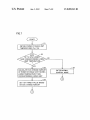
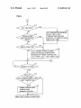
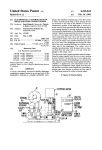
US008089243B2
(12) Ulllted States Patent
(10) Patent N0.:
Ichikawa et al.
(54)
US 8,089,243 B2
(45) Date of Patent:
POWER SUPPLY DEVICE AND VEHICLE
(56)
Jan. 3, 2012
References Cited
INCLUDING THE SAME
U.S. PATENT DOCUMENTS
(75) Inventors: Shlnjl IchIkaWa, Toyota (JP); Tetsuhlro
6,163,135 A
Ishlkawa, Toyota (JP)
9/2001 Suzuki
2002/0003417 A1
1/2002 Bito et al.
(73) Assignee: Toyota Jidosha Kabushiki Kaisha,
Toyota (JP)
(*)
Notice:
A-06-141488
5/1994
Subject to any disclaimer, the term of this
JP
A-08-098304
4/1996
U~S-Cpatent is154(1))
extended
by 400
or daysadjusted under 35
JP
A-2000-040532
2/2000
JP
A-2000-092614
3/2000
JP
A-2001-268719
9/2001
JP
A-2001-314039
11/2001
JP
A'2003'209969
7/2003
JP
A-2004-260905
9/2004
JP
A-2005-027479
Appl. N0.:
12/310,985
(22)
PCT Filed:
Oct. 9, 2007
(87)
FOREIGN PATENT DOCUMENTS
JP
(21)
(86)
12/2000 Nakayama et a1‘
2001/0024104 A1
_
A_2006_2l7757
A-2008-l17565
1/2005
PCT No..
§ 371 (0X1),
PCT/JP2007/070040
JP
JP
8/2006
5/2008
(2), (4) Date:
Mar- 131 2009
Primary Examiner * Bot Ledynh
PCT Pub‘ NO‘: W02008/050623
(74) Attorney, Agent, or Fzrm * Ol1ff& Berndge, PLC
PCT Pub. Date: May 2, 2008
(57)
.
(65)
.
.
A power supply device includes a poWer storage unit capable
Pnor Pubhcatlon Data
US 2010/0001866 A1
(30)
of being charged and a control unit controlling charging of the
Jan. 7, 2010
poWer storage unit. Control unit includes a battery ECU for
setting, at the start of charging of the poWer storage unit, a
Foreign Application Priority Data
Oct. 24, 2006
ABSTRACT
target value of state of charge of the poWer storage unit to a
?rst value based on the condition of poWer storage unit and
Setting, when a temperature increase instruction (Change
(JP) ............................... .. 2006-288874
instruction) is received after the start of charging, the target
value to a predetermined second value higher than the ?rst
value, and a converter ECU for executing the charging pro
(51)
Int‘ Cl‘
H02‘, 7/14
(52)
(58)
US. Cl. ..................................... .. 320/104; 307/101
Field of Classi?cation Search ............... .. 320/ 10.1,
Cess SO that the State ofcharge Ofthe power Storage unit attains
to the target value_
320/104; 307/101
See application ?le for complete search history.
10 Claims, 8 Drawing Sheets
(200601)
______________
40
o
12
POWER
[l] STORAGE
UNIT
PISJ
16
14
__[\_]l]
MPL\ .:
.Tl
:
CONV
1
TM
soon-ms
_>:
1
ECU
CONVERTER ECU
SOCZAZB
._§
T
TbZ
Vb2
POWER
UNIT
22
2
/
[Q
PWMI
E
1%
i
5
I,
4‘
:
I
i
I
5
WV
2
>—
5o \
26
CONV
24
2
NL2
2s
'|\PwM2
DRIVE ECU
—z
\ 2o
MNLEE
Tb1,2 PWC2
PL2
STORAGE
[)1
WV1
:
i
32 : BATTERY
_l_ 5:
i
i
1
PWMG
i
i
INV
i
3
5
' ----------------------------------------------------------------------- -"
EXTERNAL
POWER
'—
62
\ 44
(‘JP
US. Patent
Jan. 3, 2012
Sheet 1 of8
US 8,089,243 B2
322
.52n
m\ Nu[55 aN?m.
nmmN?aoNSFN2>mwa m
_:z:
|_|
r3m>wzoéobw be
Del2\3mE
1W?
,I/.fEgon
TOE
Tlm
““
m
9&68
"
Ei..NmCm/:3E5w28mnowmu@283
r_._~“.@2_n5_\ m3>mzaoy/E05
"m‘.wl@J
gom
m
3.N>z_:z:
8@n3N/2 3u/.
m
m
N
mm
»
N
US. Patent
Jan. 3, 2012
Sheet 4 of8
US 8,089,243 B2
FIG.4
INPUT SIGNAL
SMART DOOR UNLOCK SIGNAL (sou)
KEYLESS DOOR UNLOCK SIGNAL (KDU)
MANUAL TEMPERATURE INCREASE BUTTON ON SIGNAL (BONI)
CHARGE CONNECTOR OPEN SIGNAL (OP)
REMOTE TEMPERATURE INCREASE BUTTON ON SIGNAL (BONZ)
TEMPERATURE INCREASE REQUEST SIGNAL FROM HOUSE (DMN)
SIGNAL FROM PORTABLE TELEPHONE (MP)
US. Patent
Jan. 3, 2012
US 8,089,243 B2
Sheet 5 0f 8
. 08w
Ic53J9o3< \\/\Wl
a
%
\
I
f
5o<
L/\E_EQEB1
2389:o<>
E52o:<
vmEE2l lv
oME2“83
?52[,20;.
2F
n=3
CMa326m_>:5n_ .Em. *oE/mamow38>m
38now
m
n
._mu
Mi82105>7:>28
E3>
OE
m
m"<68d‘4
6
we
a“1$= .wi E2Do9Z<Q;:E>
$5; P381
US. Patent
Jan. 3, 2012
Sheet 7 0f8
US 8,089,243 B2
FIG.7
/ SI
OBTAIN POWER STORAGE UNIT
TEMPERATURES TbI, Tb2
S2
OF Tb1&Tb2 LOWER
THAN CORRESPONDING LOWER
LIMIT TEMPERATURE
f 33
CALCULATE SOC CHANGE AMOUNT
OF POWER STORAGE UNIT HAVING
LOWER TEMPERATURE THAN
CORRESPONDING LOWER LIMIT
I
r34
SET 1ST TARGET VALUE BASED
ON SOC CHANGE AMOUNT
/ S5
ENTER NORMAL
CONTROL MODE
US. Patent
Jan. 3, 2012
Sheet 8 of8
US 8,089,243 B2
FIG.8
YES
SET TIME INPUT?
TEMPERATURE
INCREASE REQUEST
INPUT?
YES
/ s11
SET TEMPERATURE INCREAsE
START TIME TO END
TEMPERATURE INCREASE
CONTROL OF POWER STORAGE
uNIT ON sET TIME
S13
YES
DRIVER GOING OUT?
NO
FULL-CHARGE POWER STORAGE
UNIT AND REALIZE TEMPERATURE
INCREASE OF POWER STORAGE UNIT
(1ST TARGET SOC —* 2ND TARGET SOC)
S15
CONNECTOR OPEN?
S16
EACH OF
Tbl & Tb2 LOWER
THAN CORRESPONDING LOWER
NO
LIMIT TEMPERATURE
POWER STORAGE UNIT
TEMPERATURE
INCREASE CONTROL
@0 (START VEHICLE CPERATI0@
US 8,089,243 B2
1
2
POWER SUPPLY DEVICE AND VEHICLE
INCLUDING THE SAME
value setting unit sets, When charging of the poWer storage
unit starts, a target value of state of charge of the poWer
storage unit to a ?rst value based on the condition of the poWer
storage unit, and sets, When the change instruction is received
after the start of charging of the poWer storage unit, the target
value to a second value higher than the ?rst value. The charge
processing unit executes a charging operation based on the
target value.
Preferably, information representing the condition of the
poWer storage unit is information of temperature around the
TECHNICAL FIELD
The present invention relates to a power supply device and
a vehicle including the same. More speci?cally, the present
invention relates to a poWer supply device including a poWer
storage unit, as Well as to a vehicle including the same.
poWer storage unit. The control unit further includes an
BACKGROUND ART
amount of change calculating unit calculating an amount of
change in state of charge of the poWer storage unit necessary
to increase temperature of the poWer storage unit. The target
value setting unit stores the second value in advance, and
calculates the ?rst value by subtracting the amount of change
from the second value.
Recently, considering environmental issues, attention has
been paid to a vehicle employing a motor as a drive poWer
source, such as an electric vehicle, a hybrid vehicle and a fuel
cell vehicle. Such a vehicle includes a poWer storage unit
implemented, for example, by a secondary battery or an elec
tric double layer capacitor for supplying electric poWer to the
motor, and converting kinetic energy to electric energy during
regenerative braking and storing such electric poWer.
More preferably, the change instruction generation unit
20
In such a vehicle employing the motor as the drive force
determines a start time of starting change of the state of
charge of the poWer storage unit based on a designated charge
end time and the amount of change, and When current time
source, in order to enhance acceleration performance and
reaches the start time, generates the change instruction.
running performance such as travel distance, greater charge/
discharge capacity of the poWer storage unit is desired. Here,
generates the change instruction in response to a temperature
a con?guration Where a plurality of poWer storage units are
mounted has been proposed as a method of increasing the
More preferably, the change instruction generation unit
25
charge/ discharge capacity of the poWer storage unit.
On the other hand, as the poWer storage unit stores electric
energy utiliZing electrochemical action, charge/ discharge
characteristics thereof are susceptible to a temperature. A
30
increase request input from outside.
More preferably, the change instruction generation unit
outputs the change instruction When it receives the tempera
ture increase request from a transmission device provided in
a house. The transmission device transmits the temperature
increase request in response to a result of detection by a
general poWer storage unit is loWer in the charge/discharge
performance as the temperature is loWer. Accordingly, in
sensor detecting a user going out from the house.
order to maintain prescribed charge/ discharge performance,
temperature management, in particular temperature increase
outputs the change instruction in response to a remote opera
control, of the poWer storage unit is important.
For example, Japanese Patent Laying-Open No. l 1-26032
discloses a heating-up device for a battery in an electric
vehicle that raises a temperature of the battery mounted on the
electric vehicle. According to this device, if a detected tem
perature of the battery is equal to or loWer than a prescribed
More preferably, the change instruction generation unit
tion by a user.
35
40
value When an instruction is issued from at least one of unlock
detection means for detecting unlock of the vehicle, timer
means for noti?cation of a set time, and input means for input
of operational information, control means carries out control
such that an output current of the battery greater than a current
required in the battery ?oWs.
The heating-up device disclosed in Japanese Patent Lay
ing-Open No. l 1-26032 increases battery temperature by the
discharge of battery. Therefore, electric poWer stored in the
battery is undesirably Wasted. The reference above, hoWever,
According to another aspect, the present invention pro
vides a vehicle, including a poWer supply device. The poWer
supply device includes a poWer storage unit capable of being
charged, and a control unit controlling charging of the poWer
storage unit. The control unit includes a change instruction
generation unit, a target value setting unit, and a charge pro
ces sing unit. The change instruction generation unit generates
a change instruction instructing change of state of charge of
the poWer storage unit. The target value setting unit sets, When
charging of the poWer storage unit starts, a target value of state
45
of charge of the poWer storage unit to a ?rst value based on the
50
instruction is received after the start of charging of the poWer
storage unit, the target value to a second value higher than the
?rst value. The charge processing unit executes a charging
operation based on the target value.
condition of the poWer storage unit, and sets, When the change
Preferably, information representing the condition of the
does not disclose any speci?c method to solve such a prob
lem.
poWer storage unit is information of temperature around the
poWer storage unit. The control unit further has an amount of
change calculating unit calculating an amount of change in
DISCLOSURE OF THE INVENTION
55
unit stores the second value in advance, and calculates the ?rst
value by subtracting the amount of change from the second
ciency.
In short, the present invention provides a poWer supply
value.
60
More preferably, the change instruction generation unit
determines a start time of starting change of the state of
charge of the poWer storage unit based on a designated charge
end time and the amount of change, and When current time
device mounted on a vehicle, including a poWer storage unit
capable of being charged, and a control unit controlling
charging of the poWer storage unit. The control unit includes
a change instruction generation unit, a target value setting
unit, and a charge processing unit. The change instruction
generation unit generates a change instruction instructing
change of state of charge of the poWer storage unit. The target
state of charge of the poWer storage unit necessary to increase
temperature of the poWer storage unit. The target value setting
An object of the present invention is to provide a poWer
supply device that can more reliably increase temperature of
poWer storage unit While preventing decrease in energy e?i
reaches the start time, generates the change instruction.
65
More preferably, the change instruction generation unit
generates the change instruction in response to a temperature
increase request input from outside.
US 8,089,243 B2
4
3
More preferably, the change instruction generation unit
Inverters 40, 42 are connected in parallel to main positive
bus MPL and main negative bus MNL, and supply/receive
electric poWer to/from poWer supply device 100. That is,
outputs the change instruction When it receives the tempera
ture increase request from a transmission device provided in
a house. The transmission device transmits the temperature
increase request in response to a result of detection by a
inverters 40, 42 convert drive electric poWer (DC electric
poWer) received through main positive bus MPL and main
negative bus MNL to AC electric poWer and supply the AC
electric poWer to motor-generators MG1, MG2 respectively.
In addition, inverters 40, 42 convert AC electric poWer gen
erated by motor-generators MG1, MG2 to DC electric poWer
and supply the resultant DC electric poWer as the regenerative
electric poWer to poWer supply device 100. By Way of
example, inverters 40, 42 are constituted of a bridge circuit
sensor detecting a user going out from the house.
More preferably, the change instruction generation unit
outputs the change instruction in response to a remote opera
tion by a user.
Therefore, according to the present invention, a poWer
supply device that can more reliably increase the temperature
of poWer storage device While preventing decrease in energy
including sWitching elements of three phases, and generate
three-phase AC electric poWer by performing a sWitching
(circuit opening/closing) operation in response to sWitching
ef?ciency can be provided.
BRIEF DESCRIPTION OF THE DRAWINGS
FIG. 1 is a schematic con?guration diagram shoWing a
substantial part of a vehicle including a poWer supply device
100 according to an embodiment of the present invention.
FIG. 2 is a schematic con?guration diagram of converters
18 and 28 according to an embodiment of the present inven
tion.
FIG. 3 is a functional block diagram of a battery ECU 32
shoWn in FIG. 1.
FIG. 4 illustrates signals input to a temperature increase
instructions PWM1, PWM2 received from drive ECU 50.
Motor-generators MG1, MG2 are con?gured to be able to
20
25
instruction generation unit 320.
FIG. 5 is a block diagram illustrating poWer supply from a
commercial poWer supply to the poWer storage unit.
FIG. 6 illustrates a con?guration of a house 200, for trans
35
40
45
[Vehicle Con?guration]
FIG. 1 is a schematic con?guration diagram shoWing a
substantial part of a vehicle including a poWer supply device
100 according to an embodiment of the present invention.
50
device 100, a ?rst inverter (INV1) 40, a second inverter
(INV2) 42, a third inverter (INV3) 44, motor-generators
MG1, MG2, and a drive ECU (Electrical Control Unit) 50.
Inverters 40, 42, motor-generators MG1, MG2, and drive
55
ues TR1, TR2 and speed target values MRN1, MRN2 to
poWer supply device 100.
In addition, in the present embodiment, inverter 44 is con
nected to main positive bus MPL and main negative bus
MNL, in parallel to inverters 40, 42. Inverter 44 is further
electrically connected to a commercial poWer supply (not
shoWn) in a house outside the vehicle through a supply line
ACL and a charge connector 60 such that electric poWer can
supply.
60
Receiving commercial electric poWer supplied from the
outside of the vehicle through charge connector 60 and supply
line ACL, inverter 44 generates DC electric poWer for supply
to poWer supply device 100. For example, inverter 44 is
implemented by a single-phase inverter so as to adapt to
In the present embodiment, poWer supply device 100
includes tWo poWer storage units. PoWer supply device 100
main negative bus MNL.
generates sWitching instructions PWM1, PWM2 and controls
inverters 40, 42 such that generated torque and speed of
motor-generators MG1, MG2 attain torque target values TR1,
TR2 and speed target values MRN1, MRN2 respectively. In
addition, drive ECU 50 outputs calculated torque target val
be supplied and received to and from the commercial poWer
eration unit to generate electric poWer from kinetic energy
and recovers the electric poWer in poWer supply device 100.
supplies and receives DC electric poWer to and from the drive
force generation unit through a main positive bus MPL and a
speci?cally, drive ECU 50 calculates torque target values
TR1, TR2 and speed target values MRN1, MRN2 of motor
generators MG1, MG2, based on a signal transmitted from
each not-shoWn sensor, a running state, variation in an accel
erator position, a stored map, or the like. Then, drive ECU 50
the same reference characters and description thereof Will not
ECU 50 con?gure a drive force generation unit generating
drive force of the vehicle. In the present embodiment, the
vehicle runs by transmitting to Wheels (not shoWn), drive
force generated by electric poWer supplied to the drive force
generation unit from poWer supply device 100. In addition,
during regeneration, the vehicle causes the drive force gen
MG2 is attained. If the drive force generation unit shoWn in
FIG. 1 is applied to such a hybrid vehicle, motor-generator
MG1 may serve solely as the generator, While motor-genera
tor MG2 may serve solely as the motor.
Drive ECU 50 executes a program stored in advance. More
In the folloWing, embodiments of the present invention Will
be described in detail With reference to the ?gures. In the
?gures, the same or corresponding portions are denoted by
Referring to FIG. 1, the vehicle includes poWer supply
48. Then, drive ECU 50 carries out control such that an
optimal ratio betWeen the drive force generated by the engine
and the drive force generated by motor-generators MG1,
BEST MODES FOR CARRYING OUT THE
INVENTION
be repeated.
generators MG1, MG2 are coupled to a poWer split device 46.
The drive force generated at motor generators MG1 and MG2
are transmitted to Wheels (not shoWn) via a drive shaft 48.
If the drive force generation unit is applied to a hybrid
vehicle, motor-generators MG1, MG2 are also coupled to a
not-shoWn engine through poWer split device 46 or drive shaft
30
mitting a temperature increase request signal from house 200
of FIG. 5 to the vehicle.
FIG. 7 is a ?oWchart for realiZing temperature increase
control by a battery ECU 32 shoWn in FIG. 3.
FIG. 8 is a ?oWchart for realiZing temperature increase
control by the battery ECU 32 shoWn in FIG. 3.
generate rotational drive force by receiving AC electric poWer
supplied from inverters 40, 42 respectively and to be able to
generate electric poWer by receiving external rotational drive
force. For example, motor-generators MG1, MG2 are imple
mented by a three-phase AC electric rotating machine includ
ing a rotor having permanent magnets embedded. Motor
electric poWer used in the house (not shoWn) outside the
65
vehicle.
A supply current detection unit 54 inserted in a positive
supply line ACLp detects a supply current IAC from the
commercial poWer supply and outputs the detected value to
US 8,089,243 B2
5
6
drive ECU 50. In addition, a supply voltage detection unit 52
vicinity of poWer storage units 10 and 20, respectively, these
may be arranged, for example, to detect temperature outside
connected between positive supply line ACLp and a negative
supply line ACLn detects a supply voltage VAC from the
the vehicle.
commercial poWer supply and outputs the detected value to
Battery ECU 32 calculates SOC (State of Charge) in
respective poWer storage units 10, 20, based on charge/dis
charge current values lb1, lb2 received from charge/ discharge
current detection units 16, 26, charge/discharge voltage val
ues Vb1, Vb2 received from charge/ discharge voltage detec
tion units 14, 24, and poWer storage unit temperatures Tb1,
Tb2 received from temperature detection units 12, 22.
Battery ECU 32 determines Whether the temperature of
drive ECU 50.
In addition, an opening and closing detection unit 62
detects opening of charge connector 60, that is, electrical
disconnection betWeen the vehicle and the commercial poWer
supply. Opening and closing detection unit 62 outputs a signal
OP indicating the detected result to poWer supply device 100.
[Con?guration of PoWer Supply Device]
PoWer supply device 100 includes a smoothing capacitor
poWer storage units 10, should be raised or not based on
C, a ?rst converter (CONV1) 18, a second converter
(CONV2) 28, a ?rst poWer storage unit 10, a second poWer
poWer storage unit temperatures Tb1, Tb2 received from tem
perature detection units 12, 22, respectively. Speci?cally, bat
storage unit 20, charge/discharge current detection units 16,
ture detection units 12, 22, and a control unit 30. Control unit
tery ECU 32 determines Whether each of poWer storage unit
temperatures Tb1, Tb2 is loWer than a corresponding loWer
30 includes a battery ECU 32 and a converter ECU 34.
limit temperature (such as —l5° C.). Then, battery ECU 32
26, charge/discharge voltage detection units 14, 24, tempera
Smoothing capacitor C is connected betWeen main positive
bus MPL and main negative bus MNL, and reduces a ?uctu
20
ating component contained in drive electric poWer output
from converters 18, 28 and regenerative electric poWer output
from the drive force generation unit.
Converters 18, 28 are provided betWeen main positive bus
MPL, main negative bus MNL andpoWer storage units 10, 20,
and perform a voltage conversion operation betWeen poWer
storage units 10, 20 and main positive bus MPL, main nega
tive bus MNL, respectively. More speci?cally, converters 18,
28 boost discharge electric poWer from poWer storage units
10, 20 to a prescribed voltage for supply as drive electric
poWer, While they doWn-convert regenerative electric poWer
supplied from the drive force generation unit to a prescribed
voltage for charging poWer storage units 10, 20. For example,
converters 18, 28 are implemented by a boost/buck chopper
circuit.
PoWer storage units 10, 20 are connected inparallel to main
positive bus MPL and main negative bus MNL With convert
25
ECU 32 sets target SOC of poWer storage unit 20 to SOC2A
30
It is noted that SOC1A<SOC1B, and SOC2A<SOC2B.
Further, the values of SOC1B and SOC2B are set to a pre
scribed value (for example, 80%) With Which poWer storage
35
40
signals PWC1 and PWC2, respectively. Accordingly, exter
poWer storage units 10 and 20, respectively. Thus, poWer
45
50
10 to converter 18 and the poWer line connecting poWer
storage unit 20 to converter 28, respectively, detect charge/
discharge voltage values Vb1, Vb2 of poWer storage units 10,
proximity of battery cells and the like constituting poWer
storage units 10, 20 respectively, detect poWer storage unit
temperatures Tb1, Tb2 Which represent ambient temperatures
of poWer storage units 10, 20, and output the result of detec
verter ECU 34 controls converter 28 in accordance With the
55
FIG. 2 is a schematic con?guration diagram of converters
18, 28 according to the embodiment of the present invention.
Referring to FIG. 2, converter 18 is constituted of a chopper
circuit 180 and a smoothing capacitor C1.
60
tric poWer received from poWer storage unit 10 in response to
sWitching instruction PWC1 from converter ECU 34, While
Chopper circuit 180, during discharge, boosts the DC elec
value obtained for example by averaging processing, based
on the result of detection by a plurality of detection elements
able to provide temperature detection units 12 and 22 in the
dance With the target value. Here, the temperature of poWer
storage unit 10 increases as poWer storage unit 10 is charged.
The same applies to poWer storage unit 20, and When the
target SOC value of poWer storage unit 20 is SOC2B, con
target value. Here, the temperature of poWer storage unit 20
increases as poWer storage unit 20 is charged.
tion to battery ECU 32. It is noted that temperature detection
units 12, 22 may be con?gured to output a representative
arranged in correspondence With a plurality of battery cells
constituting poWer storage units 10, 20. Though it is prefer
storage units 10 and 20 can be charged.
When the SOC target value of poWer storage unit 10 is
SOC1B, converter ECU 34 controls converter 18 in accor
detection to battery ECU 32 and converter ECU 34.
Charge/discharge voltage detection units 14, 24 are con
20 respectively, and output the result of detection to control
unit 30 (battery ECU 32 and converter ECU 34).
Temperature detection units 12, 22 are arranged in the
on charge/ discharge currents lb1, lb2, charge/ discharge volt
agesVb1,Vb2, temperatures Th1, Tb2 of poWer storage units,
SOC (SOC1A, SOC1B, SOC2A, SOC2B) from battery ECU
nal electric poWer is supplied through converters 18 and 28 to
Charge/discharge current detection units 16, 26 are
nected betWeen the poWer line connecting poWer storage unit
units 10 and 20 are almost fully charged.
Converter ECU 34 generates drive signals PWC1 and
PWC2 for driving converters 18 and 28, respectively, based
32 and the like. Converters 18 and 28 are controlled by drive
tric double layer capacitor.
inserted in the poWer lines connecting poWer storage units 10,
20 to converters 18, 28 respectively, detect charge/discharge
current values lb1, lb2 used in charge/discharge of poWer
storage units 10, 20 respectively, and output the result of
before starting temperature increase of poWer storage unit 20.
When temperature increase of poWer storage unit 20 is to be
started, battery ECU 32 changes the SOC target value from
SOC2A to SOC2B.
ers 18, 28 being interposed respectively. For example, poWer
storage unit 10, 20 is implemented by a secondary battery
con?gured to be capable of charge/discharge, such as a nickel
metal hydride battery or a lithium-ion battery, or by an elec
carries out temperature increase control of the poWer storage
unit of Which temperature is loWer than the corresponding
loWer limit temperature.
Battery ECU 32 sets SOC target value of poWer storage
unit 10 to SOC1A before starting temperature increase of
poWer storage unit 10. When temperature increase of poWer
storage unit 10 is to be started, battery ECU 32 changes the
SOC target value from SOC1A to SOC1B. Similarly, battery
65
chopper circuit 180, during charging, doWn converts the DC
electric poWer received through main positive bus MPL and
main negative bus MNL. Chopper circuit 180 includes a
positive bus LN1A, a negative bus LN1C, a line LN1B, tran
sistors Q1A, Q1B representing a sWitching element, diodes
D1A, D1B, and an inductor L1.
US 8,089,243 B2
8
7
As the con?guration and the operation of converter 28 are
also similar to those of converter 18 described above, detailed
Positive bus LN1A has one end connected to a collector of
transistor Q1B and the other end connected to main positive
description Will not be repeated.
bus MPL. In addition, negative bus LN1C has one end con
nected to a negative side of poWer storage unit 10 and the
other end connected to main negative bus MNL.
Transistors Q1A, Q1B are connected in series betWeen
[Structure of Battery ECU]
FIG. 3 is a functional block diagram of battery ECU 32
shoWn in FIG. 1. The functions of various blocks shoWn in
FIG. 3 may be implemented by hardWare or softWare.
Referring to FIG. 3, battery ECU 32 includes a temperature
increase instruction generation unit 320, a remaining SOC
calculating unit 321, and an SOC setting unit 322.
negative bus LN1C and positive bus LN1A. Transistor Q1A
has an emitter connected to negative bus LN1C and transistor
Q1B has the collector connected to positive bus LN1A. In
addition, diodes D1A, D1B alloWing current ?oW from the
Temperature increase instruction generation unit 320
emitter side to the collector side are connected betWeen the
determines Whether temperature increase control of poWer
storage units 10 and 20 is necessary, based on poWer storage
unit temperatures Tb1, Tb2 from temperature detection units
collector and the emitter of transistors Q1A, Q1B respec
tively. Further, inductor L1 is connected to a connection point
of transistor Q1A and transistor Q1B.
12 and 22, respectively. More speci?cally, temperature
Line LN1B has one end connected to the positive side of
poWer storage unit 10 and the other end connected to inductor
L1.
Smoothing capacitor C1 is connected betWeen line LN1B
and negative bus LN1C, and reduces the AC component con
tained in the DC voltage across line LN1B and negative bus
increase instruction generation unit 320 determines Whether
each of poWer storage unit temperatures Tb1, Tb2 is loWer
than the corresponding loWer limit temperature or not. When
it is determined that the temperature of either one of poWer
20
LN1C.
The voltage conversion operation (boost operation and
doWn-converting operation) of converter 18 Will be described
hereinafter. In the boost operation, converter ECU 34 main
tains transistor Q1B in the ON state, and turns on/offtransis
tor Q1A at a prescribed duty ratio. During the ON period of
transistor Q1A, a discharge current ?oWs from poWer storage
unit 10 to main positive bus MPL sequentially through line
LN1B, inductor L1, diode D1B, and positive bus LN1A. At
25
storage units 10, 20 is loWer than the corresponding loWer
limit temperature, temperature increase instruction genera
tion unit 320 generates the temperature increase instruction
for the poWer storage unit of Which temperature is loWer than
the corresponding loWer limit temperature, When a signal
input from the outside of the vehicle is received, or When the
current time has reached a temperature increase start time.
30
the same time, a pump current ?oWs from poWer storage unit
If both of poWer storage unit temperatures Tb1, Tb2 are
loWer than the corresponding loWer limit temperature, tem
perature increase instruction generation unit 320 generates
the temperature increase instruction for the poWer storage
unit higher in priority out of poWer storage units 10, 20. Here,
10 sequentially through line LN1B, inductor L1, transistor
priority is decided in accordance With a full charge capacity of
Q1A, and negative bus LN1C. Inductor L1 accumulates elec
the poWer storage unit, SOC of the poWer storage unit, and an
amount of deviation of the poWer storage unit temperature
from a prescribed operation temperature range.
tromagnetic energy by means of the pump current. Succes
sively, When transistor Q1A makes transition from the ON
35
As Will be described later, the signal input to temperature
increase instruction generation unit 320 includes signals
state to the OFF state, inductor L1 superimposes the accumu
lated electromagnetic energy onto the discharge current. Con
sequently, the average voltage of the DC electric poWer sup
plied from converter 18 to main positive bus MPL and main
negative bus MNL is boosted by a voltage corresponding to
the electromagnetic energy accumulated in inductor L1 in
accordance With the duty ratio.
On the other hand, in the doWn-conver‘ting operation, con
ver‘ter ECU 34 turns on/ off transistor Q1B at a prescribed duty
ratio, and maintains transistor Q1A in the OFF state. During
the ON period of transistor Q1B, the charge current ?oWs
from main positive bus MPL to poWer storage unit 10 sequen
SDU, KDU indicating that a door of the vehicle has been
unlocked With a Wireless door lock mechanism equipped in
40
45
tially through positive bus LN1A, transistor Q1B, inductor
L1, and line LN1B. Successively, When transistor Q1B makes
transition from the ON state to the OFF state, magnetic ?ux is
generated to prevent current variation in inductor L1. Accord
ingly, the charge current continues to How sequentially
through diode D1A, inductor L1 and line LN1B. MeanWhile,
from a vieWpoint of electric energy, it is solely during the ON
period of transistor Q1B that the DC electric poWer is sup
plied through main positive bus MPL and main negative bus
50
generation unit 320.
Remaining SOC calculating unit 321 calculates the amount
of change X1 of SOC necessary for increasing temperature of
55
poWer storage unit temperature Tb1 and the loWer limit tem
perature of poWer storage unit 10.
(if inductance of inductor L1 is suf?ciently large), the average
voltage of the DC electric poWer supplied from converter 18
By Way of example, remaining SOC calculating unit 321
60
plying the DC voltage across main positive bus MPL and
main negative bus MNL by the duty ratio.
In order to control such a voltage conversion operation of
converter 18, converter ECU 34 generates sWitching instruc
tion PWC1 consisting of a sWitching instruction PWC1A
controlling on/ off of transistor Q1A and a sWitching instruc
tion PWC1B controlling on/off of transistor Q1B.
poWer storage unit 10, based on the temperature T11) of poWer
storage unit 10. Remaining SOC calculating unit 321 sets the
amount of change X1 based on a difference betWeen the
MNL. Therefore, if the charge current is maintained constant
to poWer storage unit 10 is set to a value obtained by multi
the vehicle, signals BON1, BON2 indicating a state of opera
tion of a temperature increase button 400 provided in the
vicinity of a driver’s seat in the vehicle, signal OP indicating
that charge connector 60 has been opened, a signal DMN
indicating a temperature increase request from a not-shoWn
house, and an output signal MP from a portable telephone
380. As the information necessary for determining the tem
perature increase start time, an amount of change X1 in SOC
of poWer storage unit 10, an amount of change X2 in SOC of
poWer storage unit 20, and a charge end time (set time ST) set
by the user, are input to temperature increase instruction
stores a map de?ning correspondence of the amount of
change X1 to the difference betWeen the poWer storage unit
temperature Th1 and the loWer limit temperature of poWer
storage unit 10, and it may determine the amount of change
X1 by looking up the map. Alternatively, remaining SOC
65
calculating unit 321 stores in advance SOC1B as the SOC of
poWer storage unit 10 in the fully charged state, and it may
calculate current SOC of poWer storage unit 10 based on the
US 8,089,243 B2
10
power storage unit temperature Tb1, charge/discharge current
value Ib1 and charge/discharge voltage value Vb1. Here, if
nal). For example, charge connector opening signal OP is
the difference between SOC1B and the current SOC of poWer
a poWer outlet provided on the house side by the user before
the user uses the vehicle. Generated charge connector open
generated in response to removal of charge connector 60 from
storage unit 10 is larger than the amount of change X1 calcu
lated from the map, remaining SOC calculating unit 321 sets
ing signal OP is transmitted from opening and closing detec
tion unit 62 provided in charge connector 60 to temperature
increase instruction generation unit 320.
the difference as the amount of change X1. The amount of
change X2 is calculated in the similar manner as that for X1.
SOC setting unit 322 sets the target SOC value to be
applied to converter ECU 34 shoWn in FIG. 1. SOC setting
unit 322 sets the target SOC value of poWer storage unit 10 to
The ?fth input signal is the signal BON2 indicating that
temperature increase button 400 is set to the ON state by a
remote operation using a remote controller 360 by the user.
SOC1A (for example, 50%) that is loWer by the amount of
The sixth input signal is the temperature increase request
change X1 (for example, 30%) from SOC1B (for example,
signal DMN generated by the user in the house to the vehicle.
80%), before receiving the temperature increase instruction
WCM1 from temperature increase instruction generation unit
320. After receiving temperature increase instruction WCM1,
By Way of example, temperature increase request signal
DMN is issued When starting capability of the vehicle in an
environment at a loW temperature is desirably ensured by
Warming the poWer storage unit in advance before the user
SOC setting unit 322 sets the SOC target value to SOC1B.
When the temperature of poWer storage unit 20 is to be
increased, SOC setting unit 322 performs an operation similar
to that described above. The operation corresponds to the
above-described operation With temperature increase instruc
tion WCM1 changed to temperature increase instruction
uses the vehicle.
The seventh input signal is the output signal MP from
20
portable telephone 380. Generally, a user more often operates
portable telephone 380 than remote controller 360. There
fore, if temperature increase instruction generation unit 320
WCM2, SOC1A to SOC2A and SOC1B to SOC2B.
can be activated to generate the temperature increase instruc
FIG. 4 shoWs signals input to temperature increase instruc
tion generation unit 320.
Referring to FIGS. 3 and 4, seven signals in total are input
to temperature increase instruction generation unit 320.
The ?rst and second input signals are smart door unlock
signal SDU and keyless door unlock signal KDU. These
signals are signals transmitted from a body ECU (not shoWn)
controlling lock/unlock of the door to temperature increase
instruction generation unit 320 as the signal indicating unlock
tion by the user operating portable telephone 380, it Would be
more convenient for the user.
25
In response to these input signals, temperature increase
instruction generation unit 320 generates a temperature
increase instruction (WCM1 or WCM2) for the poWer storage
unit of Which temperature is loWer than the corresponding
loWer limit temperature, and outputs it to SOC setting unit
30
322.
[Temperature Increase Control Process]
As described above, in the present embodiment, poWer is
exchanged betWeen the commercial poWer supply and the
poWer storage unit. Therefore, in the present embodiment, it
of the door When the door of the vehicle is unlocked as a result
of matching betWeen an ID code included in a signal trans
mitted from a Wireless transmitter contained in the key and an
ID code provided to the vehicle, in the vehicle provided With
35
becomes possible to increase the temperature of poWer stor
age unit Without consuming electric poWer of the poWer stor
age unit. In the folloWing, temperature increase control in
accordance With the present embodiment Will be described.
40
described in Which temperature Tb1 of poWer storage unit 10
is loWer than the loWer limit value and hence temperature of
poWer storage unit 10 is increased. The same operation as Will
be described in the folloWing is performed to increase the
temperature of poWer storage unit 20.
FIG. 5 is a block diagram illustrating poWer supply from
the commercial poWer supply to the poWer storage unit.
Referring to FIG. 5, the vehicle is connected to a poWer
outlet of house 200 by a charge connector 60 through supply
a Wireless door lock mechanism.
Speci?cally, smart door unlock signal SDU is adapted to
What is called a “smart entry system,” Which is a function to
alloW lock/unlock of the door of the vehicle or start of the
engine Without using a mechanical key and represents one
form of the Wireless door lock mechanism. More speci?cally,
In the folloWing description, hoWever, an example Will be
When the smart door unlock function included in the smart
entry system (for example, a function to unlock the door When
the user carrying the smart key holds a handle outside the
driver’s seat in a sensing area outside the vehicle) is actuated,
45
the body ECU generates smart door unlock signal SDU and
transmits the signal to temperature increase instruction gen
eration unit 320.
In addition, keyless door unlock signal KDU is adapted to
a keyless entry system representing another form of the Wire
less door lock mechanism. More speci?cally, the body ECU
generates keyless door unlock signal KDU and transmits the
signal to temperature increase instruction generation unit 320
line ACL. To the vehicle, commercial poWer supplied through
50
in response to unlock of the door as a result of actuation of the
Wireless remote control function contained in the key.
55
The third input signal is the signal BON1 indicating that
temperature increase button 400 is set to the ON state by a
manual operation by the user. Temperature increase button
400 is provided in the vicinity of the driver’s seat in the
vehicle, and it is set to ON as a result of the user’s manual
60
operation or remote operation through the remote controller.
Then, temperature increase button 400 transmits the tempera
ture increase request from the user to temperature increase
instruction generation unit 320 in response to setting to ON.
The fourth input signal is the signal OP indicating that
charge connector 60 shoWn in FIG. 1 has been opened (here
inafter also referred to as the charge connector opening sig
65
commercial poWer supply line 210 to house 200 is applied. At
this time, poWer storage unit 10 as the object of temperature
increase is charged by the commercial poWer from house 200.
Therefore, poWer storage unit 10 has its temperature
increased because of self heat generation.
More speci?cally, When charge connector 60 is coupled to
the poWer outlet of house 200, supply line ACL and commer
cial poWer supply line 210 are electrically connected.
Converter ECU 34 generates a sWitching instruction
PWC1 of converter 18 that corresponds to the poWer storage
unit 10 as the object of temperature increase. Converter ECU
34 determines a target supply poWer PAC* for the commercial
poWer supply, and outputs it to drive ECU 50.
Drive ECU 50 generates a sWitching instruction PWM3 of
inverter 44, based on the applied target supply poWer PAC*.
Consequently, poWer exchange betWeen the commercial
poWer supply and poWer storage unit 10 as the object of
temperature increase starts.
US 8,089,243 B2
11
12
First, battery ECU 32 sets the target SOC value of power
sensor for detecting opening/closing of front door, sensor 206
outputs the temperature increase request When the user opens/
closes the front door.
In the vehicle, modem 56 is connected betWeen positive
storage unit 10 to SOC1A. Converter ECU 34 controls con
ver‘ter 18 such that the SOC value of poWer storage unit 10
attains to SOC1A. Speci?cally, converter ECU 34 determines
a target charge/discharge poWer P1 * of poWer storage unit 10
based on SOC1A. Then, based on poWer difference betWeen
supply line ACLp and negative supply line ACLn, enabling
transmission/reception of information to/from house 200.
Receiving the temperature request signal DMN transmitted
the determined target charge/discharge poWer P1* and the
charge/discharge poWer P1 of poWer storage unit 10, con
ver‘ter ECU 34 generates the sWitching instruction PWC1 for
from house 200 via modem 56, battery ECU 32 changes the
target SOC value output to converter ECU 34 from SOC1A to
SOC1B.
FIGS. 7 and 8 are ?oWchar‘ts for realiZing the temperature
converter 18.
Further, converter ECU 34 determines the target supply
poWer PAC* for the commercial poWer supply to be the
increase control by battery ECU 32 shoWn in FIG. 3. The
process of the ?oWchar‘ts are called from a prescribed main
routine and executed at every constant time interval or every
time prescribed conditions are satis?ed.
charge poWer Pin1 for poWer storage unit 10, and outputs the
target supply poWer PAC* to drive ECU 50. Based on poWer
difference betWeen the applied target supply poWer PAC* and
the actual value of supplied poWer PAC, drive ECU 50 gen
Referring to FIGS. 7 and 3, temperature increase instruc
tion generation unit 320 and remaining SOC calculating unit
erates a sWitching instruction PWM3 of inverter 44. It is noted
that the actual value of supply poWer PAC is calculated by
multiplying the supplied current IAC from supply current
detection unit 54 by the supplied voltage VAC from supply
voltage detection unit 52.
Receiving the temperature increase request (smart door
unlock signal SDU, keyless door unlock signal KDU or the
like), battery ECU 32 changes the target SOC value to be
20
temperature (step S2).
If either one of poWer storage unit temperatures Tb1 and
25
output to converter ECU34 from SOC1A to SOC1B. Then,
converter ECU 34 controls converter 18 such that the SOC
value of poWer storage unit 10 attains to SOC1B. Here, con
ver‘ter ECU34 changes the target charge/ discharge poWer P1 *
of poWer storage unit 10 based on SOC1B, and based on
poWer difference betWeen the target charge/ discharge poWer
P1 * and the charge/discharge poWer of poWer storage unit 10,
changes the sWitching instruction PWC1. Further, converter
ECU34 changes the target supply poWer PAC* (charge poWer
Pin1 to poWer storage unit 10), and outputs the target supply
30
35
40
mitting the temperature increase request signal from house
45
eration unit 320 determines the temperature increase instruc
tion to be output, of temperature increase instructions WCM1
and WCM2, based on poWer storage unit temperatures Tb1
and Tb2.
control of poWer storage unit 10 Will be described. SOC
setting unit 322 determines the target SOC value of poWer
storage unit 10, that is, SOC1A (?rst target SOC), based on
the amount of change X1 (remaining SOC) applied from
remaining SOC calculating unit 321 (step S4). At step S4,
SOC setting unit 322 determines SOC1A by subtracting X1
control from house 200 to poWer storage unit 100 is to be
executed, a modem 202, a control unit 204 and a sensor 206
50
nected betWeen lines of commercial poWer supply 210,
modulates information signal applied from control unit 204
from the second target value SOC (SOC1B) of poWer storage
unit 10.
If poWer storage unit temperatures Tb1 and Tb2 are both
not loWer than the corresponding loWer limit temperatures at
and superposes the result on a current ?oWing through com
mercial poWer supply line 210, and extracts a modulated
signal included in the current ?oWing through poWer supply
line 210, demodulates the signal to information signal, and
loWer than the corresponding loWer limit temperatures,
remaining SOC calculating unit 321 calculates the amount of
In the folloWing, by Way of example, temperature increase
200 shoWn in FIG. 5 to the vehicle.
are additionally installed in house 200 shoWn in FIG. 5.
Modern 202 transmits/receives information to/from a
vehicle that is electrically connected. Modem 202 is con
(YES at step S2), remaining SOC calculating unit 321 calcu
lates the amount of change of SOC (remaining SOC) that is
necessary to increase the temperature (step S3). Remaining
SOC calculating unit 321 calculates the amount of change
(amounts of change X1, X2) of SOC necessary to increase the
temperature of poWer storage unit as the object of temperature
change for the poWer storage unit of higher priority.
Further, at step S3, temperature increase instruction gen
betWeen the applied target supply poWer PAC* and the actual
Referring to FIGS. 6 and 5, When temperature increase
Tb2 is loWer than the corresponding loWer limit temperature
increase, based on the current temperature of the poWer stor
age unit.
If both of poWer storage unit temperatures Tb1 and Tb2 are
poWer PAC* to drive ECU 50. Based on poWer difference
value of supply poWer PAC, drive ECU 50 generates a sWitch
ing instruction PWM3 of inverter 44. Accordingly, the tem
perature of poWer storage unit 10 increases as poWer storage
unit 10 is charged.
FIG. 6 illustrates a con?guration of house 200, for trans
321 obtain poWer storage unit temperatures Tb1 and Tb2
from temperature detection units 12 and 22 (step S1). Tem
perature increase instruction generation unit 320 determines
Whether each of the obtained poWer storage unit temperatures
Tb1 and Tb2 is loWer than the corresponding loWer limit
55
step S2 (NO at step S2), battery ECU 32 enters normal opera
tion mode (step S5). Then, battery ECU 32 executes a process
of step S15, Which Will be described later. Here, the “normal
outputs the result to control unit 204.
operation mode” means the control mode in Which the poWer
Control unit 204 is capable of managing the state of charge
of poWer storage unit of the vehicle through transmission/
reception of information to/from the vehicle, and capable of
receiving the temperature increase request from sensor 206.
storage unit is charged Without temperature increase control.
In that case, SOC setting unit 322 sets only the second target
60
Next, referring to FIGS. 8 and 3, the process after step S4
Will be described. Temperature increase instruction genera
When a temperature increase request is applied from sensor
206, control unit 204 transmits the temperature increase
request signal DMN to the vehicle through modem 202.
Sensor 206 outputs the temperature increase request When,
SOC.
tion unit 320 determines Whether there has been a user input
of set time ST (step S1). If there has been an input of set time
65
ST (YES at step S10), temperature increase instruction gen
for example, the user going out is detected. Various sensors
eration unit 320 sets a temperature increase start time of
may be used as sensor 206. For example, if sensor 206 is a
poWer storage unit 10 such that temperature increase control
US 8,089,243 B2
14
13
of poWer storage unit 10 ends (power storage unit 10 attains to
At step S15, temperature increase instruction generation
the fully charged state) at the set time ST (step S11). As
already described, the temperature increase start time is deter
unit 320 determines Whether or not charge connector 60 has
been opened. That the charge connector 60 is opened means
end of charging from commercial poWer supply to poWer
mined based on the amount of change X1 of SOC and on the
set time ST.
storage unit 10. Temperature increase instruction generation
For instance, temperature increase instruction generation
unit 320 executes the process of step S16 if it receives a signal
unit 320 stores in advance the time-change rate of SOC of
poWer storage unit 10 When a prescribed charging current is
OP (YES at step S15), and otherWise (NO at step S15), it
repeats the determination process of step S15.
caused to How. Temperature increase instruction generation
At step S16, temperature increase instruction generation
unit 320 determines the temperature increase start time based
on the amount of change X1, the time-change rate, and the set
unit 320 determines Whether or not each of the poWer storage
unit temperatures Tb1 and Tb2 is loWer than the correspond
ing loWer limit temperature. If the temperature of poWer
storage unit at the start of temperature increase is signi?cantly
loWer than the loWer limit, or if the poWer storage unit has
time ST. Other method of determining temperature increase
start time may be available.
When the current time reaches the temperature increase
high thermal capacity, it is possible that both poWer storage
start time, temperature increase instruction generation unit
320 outputs temperature increase instruction WCM1 and
ends the process of step S11. When the process of step S11
ends, the process of step S14, Which Will be described later, is
executed.
If there is no input of set time ST (NO at step S10), tem
perature increase instruction generation unit 320 determines
Whether there is an input of temperature increase request from
outside (step S12). Here, “outside” means outside of the
20
battery ECU 32. Further, “input of temperature increase
25
step S16), temperature increase instruction generation unit
320 outputs a temperature increase instruction WCM3 for
further increasing the temperature Tb1 of poWer storage unit
request” means input of any of smart door unlock signal SDU,
keyless door unlock signal KDU, signals BON1 and BON2
from temperature increase button 400 and output signal MP
from portable telephone 380, to temperature increase instruc
tion generation unit 320. When there is an input of tempera
ture increase request (YES at step S12), temperature increase
30
instruction generation unit 320 outputs temperature increase
instruction WCM1 and executes the process of step S14. If
there is no input of temperature increase request to tempera
ture increase instruction generation unit 320 (NO at step S12),
temperature increase instruction generation unit 320 executes
the process of step S13.
35
increased close to the loWer limit temperature as a result of the
embodiment, even if it becomes necessary to consume elec
tric poWer stored in poWer storage unit 10, the amount of
40
house 200 to control unit 204. Receiving the temperature
increase request, control unit 204 controls modem 202 and
causes modem 202 to output temperature increase request
signal DMN. Temperature increase instruction generation
45
unit 320 receives the temperature increase request signal
DMN via modem 56. Speci?cally, determination as to
Whether the driver (user) goes out or not by temperature
increase instruction generation unit 320 corresponds to deter
mination as to Whether there is an input of temperature
unit 322 may set target values SOC1C and SOC2C of poWer
storage units 10 and 20 such that poWer is supplied from
poWer storage unit 10 to poWer storage unit 20. According to
18 and 28, the poWer consumption can be made smaller than
in the above-described method.
50
When the process of step S17 ends, the temperature
increase control process ends. Further if poWer storage unit
temperatures Tb1 and Tb2 are both not loWer than the corre
55
320 outputs temperature increase instruction WCM1, and
thereafter executes the process of step S14. If temperature
increase request signal DMN is not input to temperature
increase instruction generation unit 320 (NO at step S13),
temperature increase instruction generation unit 320 executes
the process of step S15, Which Will be described later.
At step S14, SOC setting unit 322 receives temperature
increase instruction WCM1 and changes the target SOC value
from SOC1A (?rst target value) to SOC1B (second target
value). Consequently, poWer storage unit 10 is charged until it
reaches the fully charged state, and temperature increase of
poWer storage unit 10 is realiZed.
poWer consumption is small.
As another possible method of further increasing the tem
perature of poWer storage unit 10, if the state of charge of
poWer storage unit 20 is not full, for example, SOC setting
this method, though electric poWer is consumed by converters
increase request signal DMN or not, by temperature increase
instruction generation unit 320.
If temperature increase request signal DMN is input to
temperature increase instruction generation unit 320 (YES at
step S13), temperature increase instruction generation unit
10 (step S17). Then, SOC setting unit 322 changes the SOC
target value from SOC1B to SOC1C (Where
SOC1B>SOC1C). As a result, poWer storage unit 10 is dis
charged, and heat generates in poWer storage unit 10. Thus,
the temperature of poWer storage unit 10 can further be
increased.
If the process of step S17 takes place, part of electric poWer
stored in poWer storage unit 10 is consumed, for example, by
converter 18, inverter 3 and the like. In most cases, hoWever,
the temperature Tb1 of poWer storage unit 10 should have
process at step S14. Therefore, according to the present
At step S13, temperature increase instruction generation
unit 320 determines Whether the driver (user) goes out or not.
As described above, if the driver goes out, a temperature
increase request is transmitted from a sensor 206 provided in
unit temperatures Tb1 and Tb2 are loWer than the correspond
ing loWer limit temperatures even after the poWer storage
units are charged to the full charged state at step S14.
By Way of example, if the temperature Tb1 of poWer stor
age unit 10 is loWer than the loWer limit temperature (YES at
sponding loWer limit temperatures at step S16 (NO at step
S16), the temperature increase control process ends. After the
end of temperature increase control process, various pro
cesses, including start of vehicle operation, are executed.
The embodiment of the present invention Will be generally
summariZed again. PoWer supply device 100 mounted on a
60
65
vehicle includes poWer storage unit 10 that is capable of being
charged and control unit 30 that controls charging of poWer
supply unit 10. Control unit 30 includes: SOC setting unit
322, Which sets, at the start of charging poWer storage unit 10,
the target value of state of charge (SOC) of poWer storage unit
10 to SOC1A (?rst value) based on the condition of poWer
storage unit 10 and When it receives temperature increase
instruction WCM1 after the start of charging, sets the target
value to predetermined SOC1B (second value) higher than
US 8,089,243 B2
15
16
SOC1A and converter ECU 34, Which executes the charging
process so that the state of charge of power storage unit 10
attains to the target value.
As described above, poWer storage unit 10 is charged to
some extent and temperature increase control is performed in
accordance With the temperature increase instruction WCM1,
so that it becomes possible to perform temperature increase
control immediately before the use by the user. As a result,
energy necessary for increasing the temperature of poWer
storage unit 10 can be reduced, and hence, temperature of
poWer storage unit 10 can more reliably be increased While
WCM2, SOC1A and SOClB by SOC2A and SOC2B, poWer
storage unit temperature Tb1 by poWer storage unit tempera
ture Tb2, and amount of change X1 by amount of change X2.
In that case, effects similar to those described above can be
attained for poWer storage unit 20.
Further, poWer supply device 100 shoWn in FIG. 1 may be
con?gured to include either one of poWer storage units 10 and
20 and a converter corresponding to the poWer storage unit.
Though temperature increase instruction generation unit
320 sets the temperature increase start time based on the input
set time ST in the present embodiment, temperature increase
instruction generation unit 320 may be con?gures to alloW
preventing decrease of energy e?iciency.
It is noted that temperature increase instruction generation
unit 320 corresponds to “change instruction generation unit”
of the present invention, and temperature increase instruction
WCM1 corresponds to the “change instruction” of the present
cancellation of the setting in accordance With a user instruc
tion.
Although the present invention has been described and
illustrated in detail, it is clearly understood that the same is by
Way of illustration and example only and is not to be taken by
Way of limitation, the scope of the present invention being
invention.
Preferably, the information representing the state of poWer
storage unit 10 is the information of temperature around
poWer storage unit 10 (poWer storage unit temperature Tb1).
Control unit 30 further includes remaining SOC calculating
unit 321 calculating amount of change (remaining SOC) X1
of poWer storage unit 10 necessary for increasing temperature
of poWer storage unit 10. SOC setting unit 322 stores SOC1B
in advance, and subtracts X1 from SOC1B to calculate
SOC1A.
More preferably, control unit 30 further includes tempera
ture increase instruction generation unit 320 that generates
interpreted by the terms of the appended claims.
20
The invention claimed is:
1. A poWer supply device mounted on a vehicle, compris
ing:
25
a poWer storage unit capable of being charged; and
a control unit controlling charging of said poWer storage
30
said control unit including
a change instruction generation unit generating a change
instruction instructing change of state of charge of said
poWer storage unit, based on information representing
unit,
temperature increase instruction WCM1. Temperature
increase instruction generation unit 320 determines a start
time of starting change of state of charge of poWer storage unit
possibility of use of said vehicle by a user,
10, based on designated charge end time (set time ST) and
a target value setting unit setting, When charging of said
amount of change X1. When the current time reaches the start
poWer storage unit starts, a target value of state of charge
time, temperature increase instruction generation unit 320
generates the temperature increase instruction WCM1.
More preferably, control unit 30 further includes tempera
of said poWer storage unit to a ?rst value based on the
35
said change instruction is received after the start of
charging of said poWer storage unit, said target value to
a second value higher than said ?rst value, and
a charge processing unit executing a charging operation
ture increase instruction generation unit 320 generating tem
perature increase instruction WCM1 in response to a tem
perature increase request from outside.
More preferably, temperature increase instruction genera
tion unit 320 outputs temperature increase instruction WCM1
When it receives temperature increase request DMN from
modern 202 provided in house 200. Modern 202 transmits
temperature increase request signal DMN in response to a
detection result of sensor 206 detecting the user going out
from house 200.
More preferably, temperature increase instruction genera
tion unit 320 outputs temperature increase instruction WCM1
in response to a remote operation by the user (operation of
remote controller 360, portable telephone 380 or the like).
40
45
storage unit; and
50
55
tion.
60
3. The poWer supply device according to claim 1, Wherein
said change instruction generation unit generates said
change instruction in response to a temperature increase
request input from outside.
4. The poWer supply device according to claim 3, Wherein
improved.
instruction WCM1 by temperature increase instruction
poWer storage unit based on a designated charge end
time and said amount of change, and When current time
reaches said start time, generates said change instruc
perature of poWer storage unit 10 can more reliably be
replaced by poWer storage unit 20, temperature increase
advance, and calculates said ?rst value by subtracting
said amount of change from said second value.
2. The poWer supply device according to claim 1, Wherein
said change instruction generation unit determines a start
time of starting change of the state of charge of said
short period of time from When SOC setting unit 322 received
temperature increase instruction WCM1. Therefore, tem
In the description above, poWer storage unit 10 may be
said control unit further includes
an amount of change calculating unit calculating an
amount of change in state of charge of said poWer stor
age unit necessary to increase temperature of said poWer
said target value setting unit stores said second value in
therefore, poWer storage unit 10 can be fully charged and the
increased While preventing decrease of energy e?iciency.
According to the present embodiment, the vehicle includes
any of the above-described poWer supply devices. This
ensures charge/ discharge performance of poWer storage unit
and, therefore, running performance of the vehicle can be
based on said target value, Wherein
information representing the condition of said poWer stor
age unit is information of temperature around said poWer
storage unit;
It becomes possible to change remaining SOC (amount of
change X1) in accordance With the poWer storage unit tem
perature Tb1 or charge end time (or running start time) and,
temperature of poWer storage unit can be increased Within a
condition of said poWer storage unit, and setting, When
said change instruction generation unit outputs said change
65
instruction When it receives said temperature increase
request from a transmission device provided in a house;
and
US 8,089,243 B2
17
18
said transmission device transmits said temperature
an amount of change calculating unit calculating an
amount of change in state of charge of said poWer stor
age unit necessary to increase temperature of said poWer
increase request in response to a result of detection by a
sensor detecting a user going out from said house.
storage unit; and
5. The poWer supply device according to claim 3, Wherein
said change instruction generation unit outputs said change
said target value setting unit stores said second value in
instruction in response to a remote operation by a user.
advance, and calculates said ?rst value by subtracting
said amount of change from said second value.
7. The vehicle according to claim 6, Wherein
said change instruction generation unit determines a start
time of starting change of the state of charge of said
poWer storage unit based on a designated charge end
time and said amount of change, and When current time
reaches said start time, generates said change instruc
tion.
8. The vehicle according to claim 6, Wherein
6. A vehicle, comprising:
a poWer supply device,
said poWer supply device including
a poWer storage unit capable of being charged, and
a control unit controlling charging of said poWer storage
unit; and
said control unit having
a change instruction generation unit generating a change
instruction instructing change of state of charge of said
poWer storage unit, based on information representing
said change instruction generation unit generates said
change instruction in response to a temperature increase
possibility of use of said vehicle by a user,
request input from outside.
a target value setting unit setting, When charging of said
poWer storage unit starts, a target value of state of charge
9. The vehicle according to claim 8, Wherein
20
said change instruction generation unit outputs said change
25
instruction When it receives said temperature increase
request from a transmission device provided in a house;
and
said transmission device transmits said temperature
increase request in response to a result of detection by a
of said poWer storage unit to a ?rst value based on the
condition of said poWer storage unit, and setting, When
said change instruction is received after the start of
charging of said poWer storage unit, said target value to
a second value higher than said ?rst value, and
a charge processing unit executing a charging operation
based on said target value, Wherein
information representing the condition of said poWer stor
age unit is information of temperature around said poWer
storage unit;
said control unit further includes
sensor detecting a user going out from said house.
10. The vehicle according to claim 8, Wherein
said change instruction generation unit outputs said change
instruction in response to a remote operation by a user.
*
*
*
*
*