1
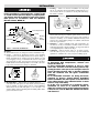
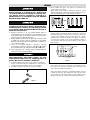
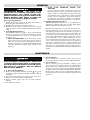
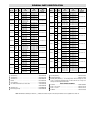
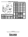
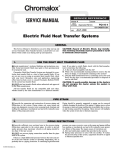
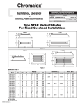
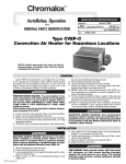
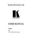
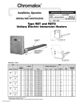
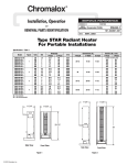
Chromalox
®
Installation, Operation
SERVICE REFERENCE
and
DIVISION
RENEWAL PARTS IDENTIFICATION
4
SALES
REFERENCE
SECTION
U-RAD
PG405-5
(Supersedes PG405-4)
161-048457-001
APRIL, 2005
DATE
Type U-RAD Electric Radiant Heaters
Conduit
Connector
Single-Element U-RAD
Double-Element U-RAD
A
A
! is used to indicate a
The Safety Alert Symbol
risk of personal injury.
Please familiarize yourself with these instructions before
attempting to install or operate this Radiant Heater.
Before Installing
1. Open carton and remove heater at the place of installation.
Mounting clamps are in parts bag in carton.
2. Check nameplate volt and watt rating against your power supply
voltage and heating requirements of your installation. This
nameplate is located on one end of the heater.
The system designer is responsible for the safety of
this equipment and should install adequate back-up
controls and safety devices with their electric heating equipment. Where the consequences of failure
could result in personal injury or property damage,
back-up controls are essential.
Specifications Table –
Length (In.)
Model
Volts
kW
Overall
Heated
Single U-Shaped Element
U-RAD-2
U-RAD-2V
U-RAD-3
U-RAD-3V
U-RAD-4V
U-RAD-4
U-RAD-5V
U-RAD-5
U-RAD-6V
U-RAD-6
U-RAD-7V
U-RAD-7
© 2010 Chromalox, Inc.
120 or 240
208 or 275
120 or 240
208 or 275
208 or 275
240 or 480
208 or 275
240 or 480
208 or 275
240 or 480
208 or 275
240 or 480
800
12-3/4
8-5/16
1100
15-7/8
11-7/16
1800
23-13/16
19-3/8
2500
31-1/4
26-13/16
3000
37-1/4
32-13/16
3600
43-3/8
38-15/16
B
B
Model
Volts
Length (In.)
kW
Overall
Heated
1600
25-1/2
16-5/8
1900
28-5/8
19-3/4
2200
31-3/4
22-7/8
2600
36-9/16
27-11/16
2900
39-11/16
30-13/16
3600
47-9/16
38-11/16
3300
44
35-1/8
3600
47-1/8
38-1/4
4300
55-1/16
46-3/16
5000
62-7/16
53-9/16
3800
50
41-1/8
4100
53-1/8
44-1/4
4800
61-1/16
52-3/16
5500
68-1/2
59-5/8
6000
74-1/2
65-5/8
4400
56-1/8
47-1/4
4700
59-1/4
50-3/8
5400
67-1/8
58-1/4
6100
74-1/2
65-5/8
6600
80-5/8
71-3/4
7200
86-3/4
77-7/8
Two U-Shaped Elements
U-RAD-22
U-RAD-22V
U-RAD-32
U-RAD-32V
U-RAD-33
U-RAD-33V
U-RAD-42V
U-RAD-42
U-RAD-43V
U-RAD-43
U-RAD-44V
U-RAD-44
U-RAD-52V
U-RAD-52
U-RAD-53V
U-RAD-53
U-RAD-54V
U-RAD-54
U-RAD-55V
U-RAD-55
U-RAD-62V
U-RAD-62
U-RAD-63V
U-RAD-63
U-RAD-64V
U-RAD-64
U-RAD-65V
U-RAD-65
U-RAD-66V
U-RAD-66
U-RAD-72V
U-RAD-72
U-RAD-73V
U-RAD-73
U-RAD-74V
U-RAD-74
U-RAD-75V
U-RAD-75
U-RAD-76V
U-RAD-76
U-RAD-77V
U-RAD-77
120 or 240
208 or 275
120 or 240
208 or 275
120 or 240
208 or 275
208 or 275
240
208 or 275
240
208 or 275
240
208 or 275
240
208 or 275
240
208 or 275
240 or 480
208 or 275
240 or 480
208 or 275
240
208 or 275
240
208 or 275
240 or 480
208 or 275
240 or 480
208 or 275
240 or 480
208 or 275
240
208 or 275
240
208 or 275
240 or 480
208 or 275
240 or 480
208 or 275
240 or 480
208 or 275
240 or 480
INSTALLATION
ELECTRIC SHOCK HAZARD. Disconnect all power
before installing or servicing heater. Failure to do
so could result in personal injury or property damage. Heater must be installed or serviced by a qualified person in accordance with the National
Electrical Code, NFPA 70.
4. Framing — Where an extensive installation is being made,
the use of continuous slot metal framing manufactured by several concerns will be of assistance in saving time and money.
The frame is reusable.
Mounting Frame
Insulation
Reflector
Spacer Sheet
1/4”
Interlocking Connector
2-3/8” 1-7/8”
Housing
Mounting
Clamp
Assembly
Terminal Cover
Terminal Block
Element
Polished Aluminum Reflector
Figure 1 — Heater Parts and Dimensions
3-11/16”
Mounting
1. These radiant heaters are designed for indoor installation only.
2. Clamps — Heaters are mounted by means of the mounting
clamp and 3/8” bolt assembly which is used as shown in Fig. 2.
Clamp assembly may be attached to heater by sliding over end
or by snapping over top of extruded frame section at any point
along its length (see Fig. 3). For proper heater support, the maximum distance between clamps must not exceed 48”. On extralong heaters, more than two clamps are furnished.
2-3/8”
2-15/16”
3-
Figure 2
Figure 3
3. Mounting Holes — When heaters are mounted adjacent to
each other in the same plane, note that distance between mounting
holes on framing to support heaters will be 3-11/16”minimum.
When heaters are not in the same plane, i.e. set at an angle to one
another, distance between mounting holes in framing will be either
greater or less than 3-11/16”.
Figure 4
5. Reflector Spacer Sheets — Where heaters are not mounted
side by side (see Fig. 4), reflector spacer sheets can be used
between heaters. These reflector spacer sheets and companion
reflectors consisting of an extruded aluminum housing with
reflector sheet and mounting clamps are available. Check with
local sales representative.
6. Insulation — Where unusually high work temperatures are
encountered, it may be desirable to insulate backs of heaters
with high-temperature fibrous insulation. A suggested method
of accomplishing this is indicated in Fig. 4.
7. Ventilation — Where solvents, water, etc. are being evaporated from work in process, it is necessary to provide substantial
quantities of ventilation air to carry away the resulting vapors.
FIRE HAZARD. Since Radiant heaters are capable
of developing high temperatures, extreme care
should be taken to:
A. Keep combustible materials at least 6” away
form sides and back of heater housing and its supporting brackets and spaced far enough in front of
heater (heating element side) so thermal radiation
from the elements will not ignite combustible
materials.
B. If combustible materials are being processed,
stoppage of process should initiate immediate
heater shutdown and interception of residual heat
from radiant heaters (use radiation baffles or move
heaters away from work).
C. In the case of solvents of an explosive nature,
ventilation air must be in sufficient volume to
dilute the solvent vapor so that explosive mixtures
cannot occur, refer to NFPA 86, Standard for Ovens
and Furnaces.
WIRING
ELECTRIC SHOCK HAZARD. Disconnect all power
before installing or servicing heater. Failure to do
so could result in personal injury or property damage. Heater must be installed or serviced by a
qualified person in accordance with the National
Electrical Code, NFPA 70.
7. Hold terminal with pliers and tighten the terminal screw
securely with a screwdriver.
Note: Where circuit wiring is installed in locations of high
ambient temperature, conductors should be insulated in accordance with requirements for temperature and voltage.
Wrong
Right
Radiant
Heaters
ELECTRIC SHOCK HAZARD.
Any installation
involving electric heaters must be performed by a
qualified person and must be effectively grounded
in accordance with the National Electrical Code to
eliminate shock hazard.
1. Electrical connection to the type U-RAD Radiant Heater is
made through the 7/8” dia. opening in the end of the terminal cover of
the element assembly. A 1/2” flexible conduit connector is provided
with each element assembly for this purpose.
2. Wiring should be run in flexible or rigid metal conduit and must
be installed in accordance with the requirements of the National
Electrical Code and such other local requirements by a qualified person as defined in the NEC.
3. Access to the element terminals is obtained by removing
the mounting bolt and nut (see Figure 8, item 16 and 18 ) and sliding the terminal end of the element assembly out of the housing.
4. Wires supplying power to heating element terminals shall have
insulation rated for 150°C minimum.
High temperatures will oxidize copper. Use only
nickel-plated copper wire for supplying power to
heater. Do not use aluminum conductors.
5. A sufficient length of this wire (not less than 12”) should be
used to extend from each heater terminal into a connection box
location where the temperature does not exceed 300˚F.
6. Assemble terminal, screw and wire as shown in Fig. 5.
L1
L1
L2
L2
Figure 6
8. SERIES CONNECTION of Radiant Heaters of equal volt
and watt rating is permitted in all line voltages up to 600 volts.
In making such series connections it is necessary to observe the
“right” (series-parallel) connection rather than the “wrong”
(parallel-series) connection both shown in Figure 6. If heaters
are connected according to the “wrong” illustration, failure of
any one heater will cause progressive failure of other heaters
still operating.
3 Conductors
in 1 Conduit
A
B
C
D
E
F
Radiant
Heaters
L1
L2
L3
3 Conductors
in 1 Conduit
Figure 7
9. DELTA CONNECTIONS — When heaters occur in multiples of three, they may be connected to, and balanced across,
three-phase lines. The most commonly used connection is the
delta connection illustrated in Figure 7.
Three phase Delta connections to minimize inductive effect in
conduits are made per this diagram. The rule: run all 3 threephase conductors in the same conduit as far as possible. For single-phase, run only two conductors and follow the same rule.
Figure 5
OPERATION
FIRE/EXPOSION HAZARD.
This heater is not
intended for use in hazardous atmospheres where
flammable vapors, gases, liquids or other combustible atmospheres are present as defined in the
National Electrical Code. Failure to comply can
result in personal injury or property damage.
Before energizing this heater:
1. Be sure all electrical connections are tightly made. Hold terminal with pliers when tightening screw.
2. Be sure that all conductors are properly insulated.
3. Be sure that all element assemblies have been properly
replaced, and that secondary insulation bushings have not been
omitted.
A. Controlling Radiant Intensity —
Standard Radiant Heaters are built to operate at approximately
40 watts per sq. inch on the element sheath. When it is desired
to reduce radiant intensity, one or more of the following methods may be used.
1. INPUT CONTROLLERS. These motor-driven cycling
devices can be used to vary heater output capacity from 4 to
100%. They are usually connected in holding coil circuit of
magnetic contactors. See Chromalox Radiant Heater Manual
for further information regarding Input Controllers and
Contactors.
2. SOLID STATE THYRISTOR POWER CONTROLLERS.
For best non-contact control of radiant heat, a Series #6
Chromalox Thyristor Power Controller with manual potentiometer setting is recommended. Truly proportional output
of from 0-100% can be easily dialed-in to suit the particular
product or process requirements. The Series #6 panels are
pre-engineered, pre-packaged assemblies in an enclosure
with circuit disconnect provided and ready for installation.
B. Maximum Ambient Temperatures —
CHROMALOX Radiant Heaters are not recommended for
applications in ambient temperature exceeding 450˚F. Higher
ambient temperatures mean shorter heater life.
Maximum work temperature in a given time depends on several factors: Reflectivity of work, specific heat of work, mass of
work, kW input and losses from oven, and time of exposure. As
work temperature increases, the work loses heat by radiation and
by convection to the surrounding ambient. Although it is a general principle of Radiant Heater application that work temperature conventionally exceeds ambient temperature, in cases
where extremely high work temperatures are desired, it is necessary to enclose the heaters in order to increase the ambient. If
evaporation of a liquid is desired as a result of increasing work
temperature, it is necessary to provide ventilation air in order to
carry away the evaporated liquid. Under carefully engineered
circumstances, a maximum work temperature of 600˚F may be
attained.
MAINTENANCE
ELECTRIC SHOCK HAZARD. Disconnect all power
before installing or servicing heater. Failure to do
so could result in personal injury or property damage. Heater must be installed or serviced by a qualified person in accordance with the National
Electrical Code, NFPA 70.
A. To Remove Heating Element —
1. Remove element assembly mounting nut and bolt 18 and 16 and
element support clips (see Figure 8) and slide element assembly out
of housing.
2. Disconnect heating element from electrical leads at both ends.
3. Remove screws from porcelain terminal blocks.
4. Remove element support clips and secondary insulating
bushings.
5. Lift element out of heater.
B. To Install Element —
Observe instructions for removing element and proceed in
reverse fashion. Be sure to replace secondary insulating bushings.
C. Care of Reflectors —
Reflectors should be cleaned periodically. A mild soap and
water solution or fine cleaning powder is best although more
drastic means may be required if reflectors are badly soiled by
chemical or other deposits. The reflector is aluminum. DO NOT
use alkali cleaners since alkalies will dull reflector. Mild nonalkaline cleaners, such as used for scouring kitchen sinks, may
be used. Reflectors are replaceable and may be purchased from
Chromalox.
RENEWAL PARTS IDENTIFICATION
Model
Volts
kW
208
U-RAD-43
240
2900
275
U-RAD-44
208
240
275
3600
208
U-RAD-52
240
3300
275
208
U-RAD-53
240
3600
275
208
240
U-RAD-54
4300
275
480
U-RAD-55
208
240
275
480
5000
208
U-RAD-62
240
3800
275
208
U-RAD-63
240
4100
275
208
240
U-RAD-64
4800
275
480
2
3
4
Element
Reflector
Aluminum
Housing
UTU-4-208V
UTU-3-208V
UTU-4-240V
UTU-3-240V
UTU-4-275V
UTU-3-275V
UTU-4(2)-208V
UTU-4(2)-240V
UTU-4(2)-275V
UTU-5-208V
UTU-2-208V
UTU-5-240V
UTU-2-240V
UTU-5-275V
UTU-2-275V
UTU-5-208V
UTU-3-208V
UTU-5-240V
UTU-3-240V
UTU-5-275V
UTU-3-275V
UTU-5-208V
UTU-4-208V
UTU-5-240V
UTU-4-240V
UTU-5-275V
UTU-4-275V
UTU-5-480V
UTU-4-480V
UTU-5(2)-208V
UTU-5(2)-240V
UTU-5(2)-275V
UTU-5(2)-480V
UTU-6-208V
UTU-2-208V
UTU-6-240V
UTU-2-240V
UTU-6-275V
UTU-2-275V
UTU-6-208V
UTU-3-208V
UTU-6-240V
UTU-3-240V
UTU-6-275V
UTU-3-275V
UTU-6-208V
UTU-4-208V
UTU-6-240V
UTU-4-240V
UTU-6-275V
UTU-4-275V
UTU-6-480V
UTU-4-480V
234-016383-003
234-016383-002
234-016383-003
234-016383-002
234-016383-003
234-016383-002
152-016376-005
234-016383-003 (2)
152-016376-006
234-016383-004
234-016383-001
234-016383-004
234-016383-001
234-016383-004
234-016383-001
234-016383-004
234-016383-002
234-016383-004
234-016383-002
234-016383-004
234-016383-002
234-016383-004
234-016383-003
234-016383-004
234-016383-003
234-016383-004
234-016383-003
234-016383-004
234-016383-003
234-016383-004 (2)
234-016383-004 (2)
234-016383-004 (2)
234-016383-004 (2)
234-016383-005
234-016383-001
234-016383-005
234-016383-001
234-016383-005
234-016383-001
234-016383-005
234-016383-002
234-016383-005
234-016383-002
234-016383-005
234-016383-002
234-016383-005
234-016383-003
234-016383-005
234-016383-003
234-016383-005
234-016383-003
234-016383-005
234-016383-003
Model
Volts
kW
208
240
U-RAD-65
5500
275
480
U-RAD-66
152-016376-007
208
240
275
480
6000
208
U-RAD-72
240
4400
275
152-016376-008
208
U-RAD-73
240
4700
275
152-016376-009
208
240
U-RAD-74
5400
275
152-016376-010
480
208
240
152-016376-011
U-RAD-75
6100
275
480
208
152-016376-012
240
U-RAD-76
6600
275
480
152-016376-013
U-RAD-77
208
240
275
480
7200
2
3
4
Element
Reflector
Aluminum
Housing
UTU-6-208V
UTU-5-208V
UTU-6-240V
UTU-5-240V
UTU-6-275V
UTU-5-275V
UTU-6-480V
UTU-5-480V
UTU-6(2)-208V
UTU-6(2)-240V
UTU-6(2)-275V
UTU-6(2)-480V
UTU-7-208V
UTU-2-208V
UTU-7-240V
UTU-2-240V
UTU-7-275V
UTU-2-275V
UTU-7-208V
UTU-3-208V
UTU-7-240V
UTU-3-240V
UTU-7-275V
UTU-3-275V
UTU-7-208V
UTU-4-208V
UTU-7-240V
UTU-4-240V
UTU-7-275V
UTU-4-275V
UTU-7-480V
UTU-4-480V
UTU-7-208V
UTU-5-208V
UTU-7-240V
UTU-5-240V
UTU-7-275V
UTU-5-275V
UTU-7-480V
UTU-5-480V
UTU-7-208V
UTU-6-208V
UTU-7-240V
UTU-6-240V
UTU-7-275V
UTU-6-275V
UTU-7-480V
UTU-6-480V
UTU-7(2)-208V
UTU-7(2)-240V
UTU-7(2)-275V
UTU-7(2)-480V
234-016383-005
234-016383-004
234-016383-005
234-016383-004
234-016383-005
234-016383-004
234-016383-005
234-016383-004
234-016383-005 (2)
234-016383-005 (2)
234-016383-005 (2)
234-016383-005 (2)
234-016383-006
234-016383-001
234-016383-006
234-016383-001
234-016383-006
234-016383-001
234-016383-006
234-016383-002
234-016383-006
234-016383-002
234-016383-006
234-016383-002
234-016383-006
234-016383-003
234-016383-006
234-016383-003
234-016383-006
234-016383-003
234-016383-006
234-016383-003
234-016383-006
234-016383-004
234-016383-006
234-016383-004
234-016383-006
234-016383-004
234-016383-006
234-016383-004
234-016383-006
234-016383-005
234-016383-006
234-016383-005
234-016383-006
234-016383-005
234-016383-006
234-016383-005
234-016383-006 (2)
234-016383-006 (2)
234-016383-006 (2)
234-016383-006 (2)
152-016376-014
152-016376-015
152-016376-016
152-016376-017
152-016376-018
152-016376-015
152-016376-019
152-016376-020
STANDARD PARTS USED ON ALL HEATERS
5 Terminal Block . . . . . . . . . . . . . . . . . . . . . . . . . . . . . . . . . . . . . . . .303-014316-001
6 Terminal Block . . . . . . . . . . . . . . . . . . . . . . . . . . . . . . . . . . . . . . . .303-014317-001
13 Insulating Bushing . . . . . . . . . . . . . . . . . . . . . . . . . . . . . . . . . . . . .032-013454-001
7 Terminal Cover . . . . . . . . . . . . . . . . . . . . . . . . . . . . . . . . . . . . . . .080-016868-001
15 Mounting Clamp Parts Bag — For mounting heaters with overall length less than
8 Bracket . . . . . . . . . . . . . . . . . . . . . . . . . . . . . . . . . . . . . . . . . . . . .027-016372-001
74-1/2”, use Parts Bag 168-013071-001. For heaters with 74-1/2” or larger overall length, use Parts Bag 168-013071-002.
9 Spacer Bushing . . . . . . . . . . . . . . . . . . . . . . . . . . . . . . . . . . . . . . .032-075525-012
10 1/2” Flexible Conduit Connector and Locknut . . . . . . . . . . . . . . . .119-075454-005
200-075482-002
11 Terminal Screw . . . . . . . . . . . . . . . . . . . . . . . . . . . . . . . . . . . . . . .248-046044-002
12 Element Support Clip . . . . . . . . . . . . . . . . . . . . . . . . . . . . . . . . . . .059-014304-002
14 Bushing Retaining Clip . . . . . . . . . . . . . . . . . . . . . . . . . . . . . . . . .059-017175-001
MISCELLANEOUS HARDWARE
16 #8-32 Nut . . . . . . . . . . . . . . . . . . . . . . . . . . . . . . . . . . . . . . . . . . .200-075520-064
17 #8-32 x 1-3/4” Screws . . . . . . . . . . . . . . . . . . . . . . . . . . . . . . . . .248-075512-194
18 #8-32 x 1” Screws . . . . . . . . . . . . . . . . . . . . . . . . . . . . . . . . . . . . .248-075512-185
19 #8 Washer . . . . . . . . . . . . . . . . . . . . . . . . . . . . . . . . . . . . . . . . . . .328-075528-036
Note: Part Numbers suffixed by a number in ( ) indicates the number of parts of the same part number used or supplied if more than one.
RENEWAL PARTS IDENTIFICATION
17
Model
7
U-RAD-3
19
Element
Support
Clip
Assembly
U-RAD-4
5
10
6
12
U-RAD-5
2
13
11
8
U-RAD-6
16
U-RAD-7
14
4
U-RAD-22
3
18
Volts
120
208
240
275
208
240
275
480
208
240
275
480
208
240
275
480
208
240
275
480
120
208
240
275
kW
1100
1800
2500
3000
3600
1600
120
9
16
208
U-RAD-32
1900
240
1 Element assembly includes all parts shown except items3
and4
For element assembly part number, add prefix “R” to Element part
number 2 Ex: R UTU-6-208V.
2
3
4
Model
Volts
kW
Element
Reflector
Aluminum
Housing
U-RAD-2
120
208
240
275
800
UTU-2-120V
UTU-2-208V
UTU-2-240V
UTU-2-275V
234-016383-001
152-016384-001
275
U-RAD-33
120
208
240
275
2200
208
U-RAD-42
240
2600
275
2
3
4
Element
Reflector
Aluminum
Housing
UTU-3-120V
UTU-3-208V
UTU-3-240V
UTU-3-275V
UTU-4-208V
UTU-4-240V
UTU-4-275V
UTU-4-480V
UTU-5-208V
UTU-5-240V
UTU-5-275V
UTU-5-480V
UTU-6-208V
UTU-6-240V
UTU-6-275V
UTU-6-480V
UTU-7-208V
UTU-7-240V
UTU-7-275V
UTU-7-480V
UTU-2(2)-120V
UTU-2(2)-208V
UTU-2(2)-240V
UTU-2(2)-275V
UTU-3-120V
UTU-2-120V
UTU-3-208V
UTU-2-208V
UTU-3-240V
UTU-2-240V
UTU-3-275V
UTU-2-275V
UTU-3(2)-120V
UTU-3(2)-208V
UTU-3(2)-240V
UTU-3(2)-275V
UTU-4-208V
UTU-2-208V
UTU-4-240V
UTU-2-240V
UTU-4-275V
UTU-2-275V
Limited Warranty:
Please refer to the Chromalox limited warranty applicable to this product at
http://www.chromalox.com/customer-service/policies/termsofsale.aspx.
2150 N. RULON WHITE BLVD., OGDEN, UT 84404
Phone: 1-800-368-2493
www.chromalox.com
234-016383-002
152-016384-002
234-016383-003
152-016384-003
234-016383-004
152-016384-004
234-016383-005
152-016384-005
234-016383-006
152-016384-006
234-016383-001 (2)
152-016376-001
234-016383-002
234-016383-001
234-016383-002
234-016383-001
234-016383-002
234-016383-001
234-016383-002
234-016383-001
152-016376-002
234-016383-002 (2)
152-016376-003
234-016383-003
234-016383-001
234-016383-003
234-016383-001
234-016383-003
234-016383-001
152-016376-004