1
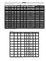
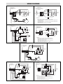
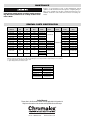
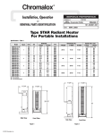
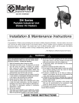
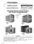
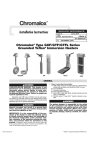
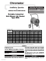
Chromalox
®
Installation, Operation
DIVISION
and
4
SECTION
SALES
(Supersedes PG422-1)
PF-497)
REFERENCE (Supersedes
RENEWAL PARTS IDENTIFICATION
DRA
PF497-1
161-304812-001
DATE
NOVEMBER, 2002
Portable Industrial
Unit Blower Air Heater
Type DRA
Specifications – Table 1
Electrical Data (60 Hz)
Dimensions (In.)
Model
DRA-07-83
DRA-07-23
DRA-10-83
DRA-10-23
DRA-15-83
DRA-15-23
DRA-15-43
DRA-15-63
DRA-20-23
DRA-20-43
DRA-20-63
DRA-30-43
DRA-30-63
Volts
kW
Phase
Amps* 1/3 Ph
BTU
Height
Width
Depth
208
240/208
208
240/208
208
240/208
480
600
240/208
480
600
480
600
7.5
7.5/5.6
9.75
9.75/7.3
15
15/11.2
15
15
19.5/15
20
20
30
30
1 and 3
1 and 3
1 and 3
1 and 3
3
3
1 and 3
1 and 3
3
1 and 3
1 and 3
3
3
36.3/21.0
31.5/18.3**
47.1/27.3
40.8/23.7**
41.8
36.3**
31.4/18.2
25.2/14.6
47.1**
42.0/24.4
33.5/19.4
36.3
20.1
25,590
25,590
33,267
33,267
51,180
51,180
51,180
51,180
66,534
68,240
68,240
102,360
102,360
34.25
34.25
34.25
34.25
34.25
34.25
34.25
34.25
34.25
34.25
34.25
34.25
34.25
27.5
27.5
27.5
27.5
27.5
27.5
27.5
27.5
27.5
27.5
27.5
27.5
27.5
25
25
25
25
25
25
25
25
26.5
26.5
26.5
26.5
26.5
* = Includes motor amps
** = Ratings shown are for 240V, 208V amperage is 86% of 240V value.
Models shown as 1 and 3 phase are factory wired for 3 phase operation and can be field wired for single phase.
GENERAL
IMPORTANT:
SAVE THESE INSTRUCTIONS
such fabrics away from heater. Do not operate
heater where flammable vapors, gases or liquids
are present. Heaters in the heat mode should not
be operated in room temperatures above 80°F. Fan
motor is not designed to operate in ambients below
-40°F.
Risk of fire. Do not use as a residential or household heater.
To avoid personal injury read “IMPORTANT
INSTRUCTIONS” on page 2 before installation or
operation of heater.
Hazard of Fire or Discoloration of Temperature
Sensitive Fabrics. Do not use as a residential or
household heater. Keep combustible material and
© 2010 Chromalox, Inc.
Keep electrical cords and combustible materials,
such as drapes and other furnishings, away from
heater.
IMPORTANT INSTRUCTIONS
When using electrical appliances, basic precautions should always
be followed to reduce the risk of fire, electric shock and injury to
persons, including the following:
1. Read all instructions before using this heater.
2. This heater is hot when in use. To avoid burns, do not let bare
skin touch hot surfaces. If provided, use handles when moving
this heater. Keep combustible materials, such as furniture, pillows, bedding, papers, clothes, and curtains at least 3 feet (0.9 m)
from the front of the heater and keep them away from the sides
and rear.
3. Extreme caution is necessary when any heater is used by or
near children or handicapped individuals and whenever the
heater is left operating and unattended.
4. Always disconnect heater when not in use.
5. Do not operate any heater with a damaged cord or plug or after
the heater malfunctions, has been dropped or damaged in any
manner. Return heater to authorized service facility for examination, electrical or mechanical adjustments, or repair.
6. Do not use outdoors.
7. This heater is not intended for use in bathrooms, laundry areas
and similar indoor locations. Never locate heater where it may
fall into a bathtub or other water container.
8. Do not run cord under carpeting. Do not cover cord with throw
rugs, runners or the like. Arrange cord away from traffic area
and where it will not be tripped over.
9. To disconnect heater, turn thermostat off, then remove plug
from outlet.
10. Connect to properly grounded outlets only.
11. Do not insert or allow foreign objects to enter any ventilation
or exhaust opening as this may cause an electric shock, fire or
damage the heater.
12. To prevent a possible fire, do not block air intakes or exhaust
in any manner. Do not use on soft surfaces, like a bed, where
opening may become blocked.
13. A heater has hot and arcing or sparking parts inside.Do not use
it in areas where gasoline, paint or flammable liquids are used
or stored.
14. Use this heater only as described in this manual. Any other use
not recommended by the manufacturer may cause fire, electric
shock or injury to persons.
15. This heater is not intended for use with an extension cord.
16.
SAVE THESE INSTRUCTIONS.
ASSEMBLY INSTRUCTIONS
The Chromalox DRA is shipped fully assembled. The handle is
assembled in the lower position (dotted line Fig. 1). To position
handle in the upright position, remove bolts securing the handle to
the support legs, lift handle until the handle holes line up with the
upper holes in the support legs and insert bolts to secure the handle in the full upright position.
Tools Required
–
–
Handle
Crescent Wrench
Phillips Screwdriver
Direction of
Airflow
Bolt (
)
Nut (
)
Support Leg
Figure 1
WIRING
4. The top access panel is secured by 4 screws that must be loosened to gain access.
5. A ground terminal is provided near the power terminal board.
The ground wire should be connected before other connections
are made.
6. Refer to Chart A for proper size “SO” grade cable.
7. A proper strain relief must be used with “SO” grade cable.
8. Dragon heaters are factory pre-wired for 3-phase delta operation. Some units can be converted to single phase operation by
changing the wiring. Refer to Chart A for those heaters that can
be converted to single phase. The appropriate wiring diagram
is also located on the back of the wiring compartment cover.
ELECTRIC SHOCK HAZARD. Disconnect all power
before installing or servicing heater. Failure to do
so could result in personal injury or property damage. Heater must be effectively grounded in accordance with the National Electrical Code, NFPA 70.
1. Use heater only on the voltage and frequency specified on the
nameplate.
2. All wiring should be done in accordance with local codes and
the National Electrical Code by a qualified person.
3. Branch circuit wire for connection to heater must be at least
90°C wire.
2
WIRING
Chart A — Cable and Plug Selection
Model
kW
Volts
Phase
Wiring
Diag. No.
Amps
Wire
Size
25’ Cord Set
Chromalox Catalog No.
Optional Plugs
Locking Type
Non Lock Type
DRA-07-83
DRA-07-83
DRA-07-23
DRA-07-23
DRA-07-23
DRA-07-23
7.5
7.5
5.6
5.6
7.5
7.5
208
208
208
208
240
240
1
3
1
3
1
3
1A
1
1A
1
1A
1
36.3
21.0
27.1
15.7
31.5
18.2
8/3
10/4
10/3
12/4
8/3
12/4
PLC-2508-3
PLC-2510-4
PLC-2510-3
PLC-2512-4
PLC-2508-3
PLC-2512-4
———
PGL-15-30
PGL-15-30
PGL-15-20
———
PGL-15-20
PGN-6-50
PGN-15-50
PGN-6-50
PGN-15-20
PGN-6-50
PGN-15-20
DRA-10-83
DRA-10-83
DRA-10-23
DRA-10-23
DRA-10-23
DRA-10-23
9.75
9.75
7.3
7.3
9.75
9.75
208
208
208
208
240
240
1
3
1
3
1
3
1A
1
1A
1
1A
1
47.1
27.2
35.4
20.4
40.8
23.6
6/3
8/4
8/3
10/4
6/3
10/4
PLC-2506-3
PLC-2508-4
PLC-2508-3
PLC-2510-4
PLC-2506-3
PLC-2510-4
———
PGL-15-30
———
PGL-15-30
———
———
PGN-6-50
PGN-15-50
PGN-6-50
PGN-15-50
PGN-6-50
PGN-15-50
DRA-15-83
DRA-15-23
DRA-15-23
DRA-15-43
DRA-15-43
DRA-15-93
DRA-15-93
15
11.2
15
15
15
15
15
208
208
240
480
480
600
600
3
3
3
1
3
1
3
1
1
1
2A
2
2A
2
41.8
31.4
38.3
31.5
18.2
25.2
14.6
6/4
8/4
6/4
8/3
12/4
10/3
14/4
PLC-2506-4
PLC-2508-4
PLC-2506-4
PLC-2508-3
PLC-2512-4
PLC-2510-3
PLC-2514-4
———
———
———
PGL-3763C
PGL-16-30
PGL-3763C
PGL-17-30
PGN-15-50
PGN-15-50
PGN-15-50
———
———
———
———
DRA-20-23
DRA-20-23
DRA-20-43
DRA-20-43
DRA-20-93
DRA-20-93
15
20
20
20
20
20
208
240
480
480
600
600
3
3
1
3
1
3
3
3
4A
4
4A
4
41.8
48.3
41.9
24.4
33.5
19.4
6/4
4/4
6/3
10/4
8/3
12/4
PLC-2506-4
PLC-2504-4
PLC-2506-3
PLC-2510-4
PLC-2508-3
PLC-2512-4
———
———
PGL-3763C
PGL-17-30
PGL-3763C
PGL-17-30
PGN-15-50
PGN-15-50
———
———
———
———
DRA-30-43
DRA-30-93
30
30
480
600
3
3
4
4
36.3
29.1
6/4
8/4
PLC-2506-4
PLC-2508-4
PGL-3764C
PGL-17-30
———
———
Model
Description
Power Cord based on 600V Hard Service Cord Rated 90°C
Plug selection is based on using Chromalox Cable Kits
Plug Selection
—
Fits Cable Dia.
Plug Type
Volts
Amps
Configuration
NEMA #
ANSI #
X
.385”-.780”
Locking
PGL-15-20
3 Pole, 4 Wire
250
20
G
L15-20
C73.85
G
L15-30
C73.86
G
L16-30
C73.88
G
L17-30
C73.89
—
—
—
—
6-50
C73.53
15-20
C73.59
15-50
C73.61
Y
Z
X
.385”-.780”
Locking
PGL-15-30
3 Pole, 4 Wire
250
30
Y
Z
X
.595”-1.150”
Locking
PGL-16-30
3 Pole, 4 Wire
480
30
Y
Z
X
.595”-1.150”
Locking
PGL-17-30
3 Pole, 4 Wire
600
30
Y
Z
Y
.750”-1.125”
Locking
PGL-3763C
2 Pole, 4 Wire
600
50
X
G
Y
.750”-1.125”
Locking
PGL-3765C
3 Pole, 4 Wire
600
X
50
Z
G
.625”-1.187”
Non Locking
PGN-6-50
2 Pole, 3 Wire
250
50
.390”-.775”
Non Locking
PGN-15-20
3 Pole, 4 Wire
250
20
G
Z
X
W
G
.750”-1.250”
Non Locking
PGN-15-50
3 Pole, 4 Wire
250
50
X
Z
W
The above plugs are designed to be used with specific ranges of cable diameters. If not used with Chromalox Cable Kits, check cable manufacturers cable diameter to be sure plug fits selected cable.
3
WIRING
3. Slide fitting onto cord and tighten knurled nut to secure fitting
to cord.
4. Select plug to match electrical rating of cord.
5. On opposite end of cord prepare end as directed by instructions
that are provided with the plug.
6. Attach cord assembly to heater as shown in Fig. 2 below:
Cord Preparation for Chromalox Portable Heaters
1. Determine the gage and number of conductors from the tabulation below using amps and phase from the heater nameplate.
It is not recommended that cord exceed 50 feet in length.
Max. Heater Amps
Chromalox Cord Kit*
Model No.
Cord Ga/No. Cond. and Type
1 Phase
3 Phase
15
PLC-2514-4
14/4 SO
20
PLC-2512-4
12/4 SO
30
PLC-2510-3
25
PLC-2510-4
40
PLC-2508-3
35
PLC-2508-4
55
PLC-2506-3
45
PLC-2506-4
6/4 SO
60
PLC-2504-4
4/4 SO
Run wire tie through slots in bracket
and over cord. Pull tab of wire tie to
provide cord strain relief.
90° fitting
10/3 SO
10/4 SO
8/3 SO
8/4 SO
6/3 SO
Ground
wire
*Includes 90 degree fitting and 25 foot of cord, reducers and locknut
2. Strip off outer jacket of cord and insulation from lead wires.
The tabulation below provides the strip dimensions for the various Chromalox portable heaters. See the nameplate on the
heater for the Model number.
Model No.
A
B
C
DRA - (all suffixes)
8”
1”
0.5”
Power
wires
Figure 2
"A"
"B" (Insulation strip dimension for ground wire).
"C" (Insulation strip dimension for power wires).
OPERATION
The adjustment knob controls power to the heater and fan when
turned further in the clockwise direction, with the highest temperature setting in the extreme clockwise position.
The temperature setting in the heater mode is approximately
40°F in the low setting and 100°F at the highest setting.
Note: The adjustment knob should be turned to the fan only setting after use for heating. The fan should be left on for at least 3
minutes to remove residual heat from the unit and to prevent overheating of the housing.
THERMOSTAT
Heaters include a bimetal thermostat for the automatic control
of the exiting air temperature. The thermostat knob controls the
heating elements and fan functions. The heater and fan are deenergized with the knob in the extreme clockwise position.
Turning the knob clockwise from the off position to the fan
position will energize the fan only, for use in summer cooling.
4
WIRING DIAGRAMS
Diag. 1 – FACTORY WIRED 3 PHASE
Cord by others.
Type "SO" or equal
sized to meet nameplate
requirements
L3
L2
L1
Cord by others.
Type "SO" or equal
sized to meet nameplate
requirements
6
5
3
T3
T2
T1
Diag. 1a – FIELD CONVERSION TO 1 PHASE
2
1
4
6
5
2
6
Front of
Heater
5
1
2
T2
T1
4
4
All control wiring
same as Diag. 1
Thermostat
1
3
6
Blk
Motor
Cutout
Wht
Diag. 2 – FACTORY WIRED 3 PHASE
Cord by others.
Type "SO" or equal
sized to meet nameplate
requirements
5
Diag. 2a – FIELD CONVERSION TO 1 PHASE
To T2
Cord by others.
Type "SO" or equal
sized to meet nameplate
requirements
5
3
To T3 4
1
Contactor
L3
L2
L1
6
4
3
1
3
To T3
T3
T2
T1
3
Instructions:
1. Loosen screws on load side of contactor. Remove all lead wire.
2. Insert lead wires numbers 1, 3, and 5 into box lug connector "T1". Tighten screws
on box lug connector.
3. Insert lead wires numbers 2, 4, and 6 into box lug connector "T2". Tighten screws
on box lug connector.
4. Examine wiring to make certain it is per above diagram.
Red
Blu
Contactor
6
2
2
4
6
To T1
To T2
To T1
4
2
Front of
Heater
5
1
2
Front of
Heater
3
1
4
4
6
5
1
L2
L1
3
2
All even numbered wires to T2
L2
L1
T2
T1
4
3
Front of
Heater
All odd numbered wires to T1
5
1
1
6
Fan Relay
L1
L2
A1
Black
White
T1
T2
A2
2
All control wiring
same as Diag. 2
Motor
6
3
5
Blk/Red or Grey
Instructions:
1. Loosen screws on load side of contactor. Remove all lead wire.
2. Insert lead wires numbers 1, 3, and 5 into box lug connector "T1".
Tighten screws on box lug connector.
3. Insert lead wires numbers 2, 4, and 6 into box lug connector "T2".
Tighten screws on box lug connector.
4. Examine wiring to make certain it is per above diagram.
Blk
Thermostat
1
3
4
6
Cutout
Wht
XFMR
Blk
Diag. 3 – FACTORY WIRED 3 PHASE
12
11
9
Cord by others.
Type "SO" or equal
sized to meet nameplate
requirements
8
7
To T3
3
4
4
Contactor
L3
L2
L1
To T2
11
8
3
12 Front of
Heater
7
T3
T2
T1
5
1
10
9
6
5
1
10
6
2
2
To T2 To T1
To T1
To T3
Thermostat
3
1
4
Red
Black
6
Motor
Blue
Cutout
White
Diag. 4 – FACTORY WIRED 3 PHASE
8
7
3
6
To T2
4
4
4
Contactor
11
8
3
12 Front of
Heater
Contactor
7
T3
T2
T1
5
1
10
5
1
To T3
2
L2
L1
9
6
2
10
All control wiring
same as Diag. 4
To T2 To T1
To T1
Black
White
T1
T2
A2
4
6
Cutout
8
1
1
5
2
9
6
7
Blk/Red or Grey
Wht
9
11
Instructions:
1. Loosen screws on load side of contactor. Remove all lead wire.
2. Insert lead wires numbers 1, 3, 5, 7, 9 and 11 into box lug connector "T1".
Tighten screws on box lug connector.
3. Insert lead wires numbers 2, 4, 6, 8, 10 and 12 into box lug connector "T2".
Tighten screws on box lug connector.
4. Examine wiring to make certain it is per above diagram.
XFMR
Blk
5
11
7
5
Motor
Thermostat
3
12
4
3
All odd numbered wires to T1
3
Blk
1
2
All even numbered wires to T2
T2
T1
6
Fan Relay
L1
L2
A1
12
10
8
To T3
L3
L2
L1
Diag. 4a – FIELD CONVERSION TO 1 PHASE
Cord by others.
Type "SO" or equal
sized to meet nameplate
requirements
12
11
9
Cord by others.
Type "SO" or equal
sized to meet nameplate
requirements
10
Front of
Heater
MAINTENANCE
ELECTRIC SHOCK HAZARD. Disconnect heater
from power supply before servicing and/or inspecting the heater; failure to do so may result in electrical shock.
Replace or repair damaged cords or plugs immediately. Check
tightness of all electrical connections prior to energizing Dragon.
Blow out or vacuum away any dirt or debries that may have accumulated around the control enclosure fan motor or heating elements.
RENEWAL PARTS IDENTIFICATION
Element
Part No.
Motor
Part No.
Contactor
Part No.
Control
Trans/
118-304793-001
072-304551-014
———
118-304793-002
072-304551-014
———
Model No.
Volts
kW
Phase
DRA-07-83
208
7.5
1 and 3
DRA-07-23
240
7.5
1 and 3
DRA-10-83
208
9.75
1 and 3
118-304793-003
DRA-10-23
240
9.75
1 and 3
DRA-15-83
208
15
DRA-15-23
240
15
DRA-15-43
480
DRA-15-93
DRA-20-23
Fan
Part No.
072-304551-014
———
118-304793-004
072-304551-014
———
3
118-304793-007
072-304551-014
———
3
118-304793-008
072-304551-014
———
15
1 and 3
118-304793-009
600
15
1 and 3
240
19.5
3
DRA-20-43
480
20
1 and 3
DRA-20-93
600
20
1 and 3
DRA-30-43*
480
30
3
DRA-30-93*
600
30
3
193-302120-009
193-302120-012
072-304551-008 315-304252-001
118-304793-010
193-302120-015
112-045422-007 072-304551-008 315-304252-003
118-304793-004
193-302120-009
072-304551-014
118-304793-005
193-302120-012
072-304551-008 315-304252-001
118-304793-006
193-302120-015
072-304551-008 315-304252-003
193-302120-012
072-304551-008 315-304252-001
193-302120-015
072-304551-008 315-304252-003
118-304793-011a
118-304793-013b
118-304793-012a
118-304793-014b
———
30 kW units contain two sets of three elements (six total). The ratings of the three elements on the discharge end have a lower wattage than the elements on the fan end of
heater. The ends of the elements are color coded, the lower wattage are color coded yellow and the higher wattage are color coded blue.
a. Lower wattage elements, discharge end, yellow coded
b. Higher wattage elements, fan end, blue coded
PARTS COMMON TO ALL UNITS
Description
Part No.
Wheels
333-557518-004
Grille
134-304780-002
Thermostat
300-304782-001
Thermal Cut-out
300-048038-003
Fan Relay (not used on
208 and 240V Models)
072-123534-057
Limited Warranty:
Please refer to the Chromalox limited warranty applicable to this product at
http://www.chromalox.com/customer-service/policies/termsofsale.aspx.
2150 N. RULON WHITE BLVD., OGDEN, UT 84404
Phone: 1-800-368-2493
www.chromalox.com