1
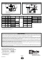
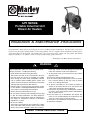
DH Series
Portable Industrial Unit
Blower Air Heaters
Installation & Maintenance Instructions
Dear Owner,
Congratulations! Thank you for purchasing this new heater by Marley Engineered Products. You have made a wise investment selecting the highest quality product in the heating industry. Please carefully read the installation and maintenance
instructions shown in this manual. You should enjoy years of efficient heating comfort with this product from Marley
Engineered Products... the industry’s leader in design, manufacturing, quality and service.
... The Employees of Marley Engineered Products
WARNING
When using electrical appliances, basic precautions should
always be followed to reduce the risk of fire, electric shock
and injury to persons, including the following:
1. Read all instructions before using this heater.
2. This heater is hot when in use. To avoid burns, do not let
bare skin touch hot surfaces. If provided, use handles
when moving this heater. Keep combustible materials,
such as furniture, pillows, bedding, papers, clothes, and
curtains at least 3 feet (0.9 m) from the front of the heater
and keep them away from the sides and rear.
3. Extreme caution is necessary when any heater is used by
or near children or handicapped individuals and whenever the heater is left operating and unattended.
4. Always disconnect heater when not in use.
5. Do not operate any heater with a damaged cord or plug
or after the heater malfunctions, has been dropped or
damaged in any manner. Return heater to authorized service facility for examination, electrical or mechanical
adjustments, or repair.
6. Do not use outdoors.
7. This heater is not intended for use in bathrooms, laundry
areas and similar indoor locations. Never locate heater
where it may fall into a bathtub or other water container.
!
8. Do not run cord under carpeting. Do not cover cord with
throw rugs, runners or the like. Arrange cord away from
traffic area and where it will not be tripped over.
9. To disconnect heater, turn thermostat off, then remove
plug from outlet.
10. Connect to properly grounded outlets only.
11. Do not insert or allow foreign objects to enter any ventilation or exhaust opening as this may cause an electric
shock, fire or damage the heater.
12. To prevent a possible fire, do not block air intakes or
exhaust in any manner. Do not use on soft surfaces, like
a bed, where opening may become blocked.
13. A heater has hot and arcing or sparking parts inside.Do
not use it in areas where gasoline, paint or flammable liquids are used or stored.
14. Use this heater only as described in this manual. Any
other use not recommended by the manufacturer may
cause fire, electric shock or injury to persons.
15. This heater is not intended for use with an extension cord.
16. Save these instructions.
SAVE THESE INSTRUCTIONS
ASSEMBLY INSTRUCTIONS
a
WARNING
!
The DH is shipped fully assembled. The handle is assembled in
the lower position (dotted line Fig. 1). To position handle in the
upright position, remove bolts securing the handle to the support
legs, lift handle until the handle holes line up with the upper holes
in the support legs and insert bolts to secure the handle in the full
upright position.
Risk of fire. Do not use as a residential or household heater.
a
WARNING
!
Hazard of Fire or Discoloration of Temperature Sensitive
Fabrics. Do not use as a residential or household heater. Keep
combustible material and such fabrics away from heater. Do
not operate heater where flammable vapors, gases or liquids
are present. Heaters in the heat mode should not be operated
in room temperatures above 80°F. Fan motor is not designed
to operate in ambients below -40°F.
Handle
Direction of
Airflow
To avoid personal injury read “IMPORTANT INSTRUCTIONS”
before installation or operation of heater.
a
WARNING
!
Keep electrical cords and combustible materials, such as
drapes and other furnishings, away from heater.
Plug Type
a
Model
Description
!
Volts Amps Configuration NEMA # ANSI #
X
.385”-.780”
Locking
LPS25124 3 Pole, 4 Wire
250
20
G
L15-20 C73.85
G
L15-30 C73.86
G
L16-30 C73.88
Y
Z
Locking
LPS25103 3 Pole, 4 Wire
250
30
Y
WARNING
ELECTRIC SHOCK HAZARD. Disconnect all power before
installing or servicing heater. Failure to do so could result in
personal injury or property damage. Heater must be effectively
grounded in accordance with the National Electrical Code,
NFPA 70.v
X
.385”-.780”
)
)
Support Leg
Figure 1
Plug Specifications
Fits Cable Dia.
Bolt (
Nut (
Z
WIRING INSTRUCTIONS
X
.595”-1.150”
Locking
LPS25104 3 Pole, 4 Wire
480
30
Y
1. Use heater only on the voltage and frequency specified on
the nameplate.
2. All wiring should be done in accordance with local codes and
the National Electrical Code by a qualified person.
3. Branch circuit wire for connection to heater must be at least
90°C wire.
4. The top access panel is secured by 4 screws that must be
loosened to gain access.
5. A ground terminal is provided near the power terminal board.
The ground wire should be connected before other
connections are made.
6. Refer to Chart A for proper size “SO” grade cable.
7. A proper strain relief must be used with “SO” grade cable.
8. Dragon heaters are factory pre-wired for 3-phase delta
operation. Some units can be converted to single phase
operation by changing the wiring. Refer to Chart A for those
heaters that can be converted to single phase. The
appropriate wiring diagram is also located on the back of the
wiring compartment cover.
Z
X
.595”-1.150”
Locking
LPS25084 3 Pole, 4 Wire
600
30
G
Y
L17-30 C73.89
Z
Y
.750”-1.125”
Locking
LPS25083 2 Pole, 4 Wire
600
50
X
—
—
—
—
6-50
C73.53
G
Y
.750”-1.125”
Locking
LPS25064 3 Pole, 4 Wire
600
X
50
Z
G
.625”-1.187”
Non Locking NPS25650 2 Pole, 3 Wire
250
50
.390”-.775”
Non Locking NPS1520 3 Pole, 4 Wire
250
20
G
Z
X
15-20 C73.59
W
G
.750”-1.250”
Non Locking NPS1550 3 Pole, 4 Wire
250
50
X
Z
15-50 C73.61
W
Chart A
MODEL
NUMBER
DH1021C*
DH0783
KW
10
7.5
VOLTS
240
208
BTUH
34,120
25,590
DH1023
10
240
34,120
DH1583
DH1523
DH1521
DH1543
15
15
15
15
208
240
240
480
51,180
51,180
51,180
51,180
DH2043
20
480
68,240
DH3043
DH3063
30
30
480
600
102,360
102,360
PH
1
1
3
1
3
3
3
1
1
3
1
3
3
3
AMPS
41.7
36.3
21
40.8
23.6
41.8
36.3
62.5
31.4/18.2
41.6/24.4
36.3
29.1
WIRING
DIAGRAM
NUMBER
N/A
1A
1
1A
1
1
1
1A
2A
2
4A
4
4
4
SHIP
WT.
65 lbs
65 lbs
65 lbs
65 lbs
65 lbs
65 lbs
65 lbs
75 lbs
75 lbs
75 lbs
WIRE
SIZE
N/A
8/3
10/4
6/3
10/4
6/4
8/4
4/4
8/3
12/4
6/3
10/4
6/4
8/4
25 FT
CORD
SET
Included*
CS25083
CS25104
CS25063
CS25104
CS25064
CS25084
CS25044
CS25083
CS25124
CS25063
CS25104
CS25064
CS25084
*Model DH1021C is shipped with 10 ft. power cord and plug.
Note: All units are factory wired for 3 phase operation. Models designated 1 and 3 phase can be field wired for single phase operation.
2
OPTIONAL PLUGS
LOCKING
NON-LOCK
TYPE
TYPE
Included
NPS25650
LPS25103
NPS1550
NPS25650
NPS1550
NPS1550
NPS1550
NPS1550
LPS25083
LPS25104
LPS25083
LPS25084
LPS25064
LPS25084
Cord Preparation for Portable Heaters
1. Determine the gage and number of conductors fromChart A using
amps and phase from the heater nameplate. It is not recommended
that cord exceed 50 feet in length.
2. Strip off outer jacket of cord and insulation from lead wires. The tabulation below provides the strip dimensions for the
various Chromalox portable heaters. See the nameplate on the heater
for the Model number.
3. Slide fitting onto cord and tighten knurled nut to secure fitting
to cord.
4. Select plug to match electrical rating of cord.
5. On opposite end of cord prepare end as directed by
instructions that are provided with the plug.
6. Attach cord assembly to heater as shown in Fig. 2 below:
Model No.
A
B
C
All Models
8”
1”
0.5”
Diag. 1 – FACTORY WIRED 3 PHASE
Cord by others.
Type "SO" or equal
sized to meet nameplate
requirements
L3
L2
L1
6
5
3
T3
T2
T1
2
1
4
Front of
Heater
3
2
4
Thermostat
1
3
4
6
Red
Blk
Blu
Motor
Cutout
Wht
Diag. 1a – FIELD CONVERSION TO 1 PHASE
Cord by others.
Type "SO" or equal
sized to meet nameplate
requirements
"A"
6
5
2
2
6
T2
T1
Front of
Heater
5
1
L2
L1
4
3
1
"B" (Insulation strip dimension for ground wire).
4
All control wiring
same as Diag. 1
"C" (Insulation strip dimension for power wires).
Run wire tie through slots in bracket and over cord.
Pull tab of wire tie to provide cord strain relief.
6
5
1
3
Instructions:
1. Loosen screws on load side of contactor. Remove all lead wire.
2. Insert lead wires numbers 1, 3, and 5 into box lug connector "T1". Tighten screws
on box lug connector.
3. Insert lead wires numbers 2, 4, and 6 into box lug connector "T2". Tighten screws
on box lug connector.
4. Examine wiring to make certain it is per above diagram.
90° fitting
Diag. 2 – FACTORY WIRED 3 PHASE
Cord by others.
Type "SO" or equal
sized to meet nameplate
requirements
Ground
wire
5
5
To T2
3
To T3 4
1
Contactor
L3
L2
L1
3
1
3
To T3
T3
T2
T1
Front of
Heater
5
1
6
2
2
2
4
6
To T1
To T2
To T1
4
6
Power
wires
Fan Relay
L1
L2
A1
Black
White
T1
T2
A2
Motor
Blk/Red or Grey
Blk
Thermostat
Figure 2
1
3
4
6
Cutout
Wht
XFMR
Blk
OPERATION INSTRUCTIONS
THERMOSTAT
Heaters include a bimetal thermostat for the automatic control
of the exiting air temperature. The thermostat knob controls the heating
elements and fan functions. The heater and fan are
de-energized with the knob in the extreme clockwise position.
Turning the knob clockwise from the off position to the fan
position will energize the fan only, for use in summer cooling.
The adjustment knob controls power to the heater and fan
when turned further in the clockwise direction, with the highest temperature setting in the extreme clockwise position.
The temperature setting in the heater mode is approximately
40°F in the low setting and 100°F at the highest setting.
Note: The adjustment knob should be turned to the fan only
setting after use for heating. The fan should be left on for at least 3 minutes to remove residual heat from the unit and to prevent overheating of
the housing.
Diag. 2a – FIELD CONVERSION TO 1 PHASE
Cord by others.
Type "SO" or equal
sized to meet nameplate
requirements
4
2
All even numbered wires to T2
L2
L1
T2
T1
3
Front of
Heater
All odd numbered wires to T1
5
1
1
2
All control wiring
same as Diag. 2
6
3
5
Instructions:
1. Loosen screws on load side of contactor. Remove all lead wire.
2. Insert lead wires numbers 1, 3, and 5 into box lug connector "T1".
Tighten screws on box lug connector.
3. Insert lead wires numbers 2, 4, and 6 into box lug connector "T2".
Tighten screws on box lug connector.
4. Examine wiring to make certain it is per above diagram.
Diag. 3 – FACTORY WIRED 3 PHASE
MAINTENANCE INSTRUCTIONS
12
11
9
Cord by others.
Type "SO" or equal
sized to meet nameplate
requirements
a
!
6
4
Contactor
WARNING
8
7
To T3
3
Electric Shock Hazard. Disconnect heater from power supply
before servicing and/or inspecting the heater; failure to do so
may result in electrical shock.
L3
L2
L1
To T2
4
4
Contactor
7
5
1
10
5
3
2
Red
Black
6
Blue
Cutout
White
6
To T2 To T1
To T1
Thermostat
3
1
4
9
6
2
1
To T3
Replace or repair damaged cords or plugs immediately. Check
tightness of all electrical connections prior to energizing the
heater. Blow out or vacuum away any dirt or debries that may
have accumulated around the control enclosure fan motor or
heating elements.
11
8
3
T3
T2
T1
Motor
10
12 Front of
Heater
Diag. 4a – FIELD CONVERSION TO 1 PHASE
Cord by others.
Type "SO" or equal
sized to meet nameplate
requirements
Diag. 4 – FACTORY WIRED 3 PHASE
12
12
11
9
Cord by others.
Type "SO" or equal
sized to meet nameplate
requirements
10
8
8
7
6
To T3
3
4
Contactor
All even numbered wires to T2
L2
L1
T2
T1
12
4
3
8
1
11
7
All odd numbered wires to T1
All control wiring
same as Diag. 4
1
5
2
L3
L2
L1
Front of
Heater
11
8
3
12 Front of
Heater
7
T3
T2
T1
10
5
1
9
6
2
5
1
9
6
To T2
4
4
Contactor
2
To T3
10
3
2
10
6
To T2 To T1
To T1
Fan Relay
L1
L2
A1
5
7
Black
White
T1
T2
A2
Motor
Blk/Red or Grey
9
Blk
11
Instructions:
1. Loosen screws on load side of contactor. Remove all lead wire.
2. Insert lead wires numbers 1, 3, 5, 7, 9 and 11 into box lug connector "T1".
Tighten screws on box lug connector.
3. Insert lead wires numbers 2, 4, 6, 8, 10 and 12 into box lug connector "T2".
Tighten screws on box lug connector.
4. Examine wiring to make certain it is per above diagram.
Thermostat
1
3
4
6
Cutout
Wht
XFMR
Blk
Renewal Parts Identification
VOLTS
KW
PHASE
ELEMENT
PART NO.
DH0783
208
7.5
1 and 3
118-304793-001
DH1023
240
9.75
1 and 3
118-304793-004
DH1583
208
15
3
118-304793-007
DH1523
240
15
3
118-304793-008
DH1543
480
15
1 and 3
118-304793-009
193-302120-012
DRA-20-23
240
19.5
3
118-304793-004
193-302120-009
072-304551-014
———
DRA-20-43
480
20
1 and 3
118-304793-005
193-302120-012
072-304551-008
315-304252-001
DRA-30-43*
480
30
3
193-302120-012
072-304551-008
315-304252-001
DRA-30-93*
600
30
3
193-302120-015
072-304551-008
315-304252-003
MODEL NO.
118-304793-011a
118-304793-013b
118-304793-012a
118-304793-014b
MOTOR
PART NO.
FAN
PART NO.
193-302120-009
112-045422-007
CONTACTOR
PART NO.
CONTROL
TRANS/
072-304551-014
———
Wheels
333-557518-004
072-304551-014
———
Grille
134-304780-002
072-304551-014
———
Thermostat
300-304782-001
072-304551-014
———
Thermal Cut-out
300-048038-003
072-304551-008
315-304252-001
PARTS COMMON TO ALL UNITS
DESCRIPTION
PART NO.
Fan Relay (not used on 072-123534-057
208 and 240V Models)
*30 kW units contain two sets of three elements (six total). The ratings of the three elements on the discharge end have a lower wattage than the elements on
the fan end of heater. The ends of the elements are color coded, the lower wattage are color coded yellow and the higher wattage are color coded blue.
a. Lower wattage elements, discharge end, yellow coded
b. Higher wattage elements, fan end, blue coded
LIMITED WARRANTY
All products manufactured by Marley Engineered Products are warranted against defects in workmanship and materials for one year from date of installation, except heating elements which are warranted against defects in workmanship and materials for five years from date of installation. This warranty does not apply to damage from accident, misuse, or alteration; nor where the connected voltage is more than 5% above the nameplate voltage; nor to equipment improperly installed or wired or maintained in
violation of the product’s installation instructions. All claims for warranty work must be accompanied by proof of the date of installation.
The customer shall be responsible for all costs incurred in the removal or reinstallation of products, including labor costs, and shipping costs incurred to return products to
Marley Engineered Products Service Center. Within the limitations of this warranty, inoperative units should be returned to the nearest Marley authorized service center or
the Marley Engineered Products Service Center, and we will repair or replace, at our option, at no charge to you with return freight paid by Marley. It is agreed that such
repair or replacement is the exclusive remedy available from Marley Engineered Products.
THE ABOVE WARRANTIES ARE IN LIEU OF ALL OTHER WARRANTIES EXPRESSED OR IMPLIED, AND ALL IMPLIED WARRANTIES OF MERCHANTABILITY AND
FITNESS FOR A PARTICULAR PURPOSE WHICH EXCEED THE AFORESAID EXPRESSED WARRANTIES ARE HEREBY DISCLAIMED AND EXCLUDED FROM THIS
AGREEMENT. MARLEY ENGINEERED PRODUCTS SHALL NOT BE LIABLE FOR CONSEQUENTIAL DAMAGES ARISING WITH RESPECT TO THE PRODUCT,
WHETHER BASED UPON NEGLIGENCE, TORT, STRICT LIABILITY, OR CONTRACT.
Some states do not allow the exclusion or limitation of incidental or consequential damages, so the above exclusion or limitation may not apply to you. This warranty gives
you specific legal rights, and you may also have other rights which vary from state to state.
For the address of your nearest authorized service center, contact Marley Engineered Products in Bennettsville, SC, at 1-800-642-4328. Merchandise returned to the factory must be accompanied by a return authorization and service identification tag, both available from Marley Engineered Products. When requesting return authorization,
include all catalog numbers shown on the products.
HOW TO OBTAIN WARRANTY SERVICE AND
WARRANTY PARTS PLUS GENERAL INFORMATION
1. Warranty Service or Parts
2. Purchase Replacement Parts
3. General Product Information
1-800-642-4328
1-800-654-3545
www.marleymep.com
Note: When obtaining service always have the following:
1. Model number of the product
2. Date of manufacture
3. Part number or description
PPD057A
5200-2653-001
06/08
4
470 Beauty Spot Rd. East
Bennettsville, SC 29512 USA