1
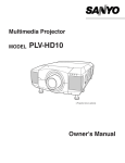
MODEL
38-VIV211-01
103-004001
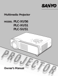
✽ Projection lens is optional.
User's Manual
TO THE OWNER
Before operating this projector, read this manual thoroughly and operate the projector properly.
This projector provides many convenient features and functions. Operating the projector properly enables you to
manage those features and maintains it in better condition for a considerable time.
Improper operation may result in not only shortening the product-life, but also malfunctions, fire hazard, or other
accidents.
If your projector seems to operate improperly, read this manual again, check operations and cable connections and try
the solutions in the “Trouble-shooting” section at the end of this booklet. If the problem still persists, contact the sales
dealer where you purchased the projector or the service center.
SAFETY PRECAUTIONS
WARNING : TO REDUCE THE RISK OF FIRE OR ELECTRIC SHOCK, DO NOT EXPOSE THIS PROJECTOR TO
RAIN OR MOISTURE.
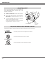
● This projector produces intense light from the projection lens. Do not stare directly into the lens. Eye damage
could result. Be especially careful that children do not stare directly into the beam.
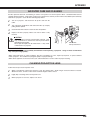
● This projector should be set in the way indicated. If not, it may result in a fire hazard.
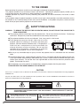
● Take appropriate space on the top, sides and rear of the
projector cabinet for allowing air circulation and cooling the
projector. Minimum distance should be taken. If the projector is
to be built into a compartment or similarly enclosed, the
minimum distances must be maintained. Do not cover the
ventilation slot on the projector. Heat build-up can reduce the
service life of your projector, and can also be dangerous.
SIDE and TOP
REAR
3.3" (1 m)
3.3" (1 m)
3.3" (1 m)
3.3" (1 m)
● Do not put any flammable object or spray can near the projector, hot air is exhausted from the ventilation
holes.
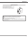
● The Remote Control Unit, supplied with this projector, emits a laser beam with the laser pointer function from
Laser Light Window while pressing LASER button (for 1 minute / LASER POINTER INDICATOR lights red to
indicate laser emission). Do not look into Laser Light Window or shine the laser beam on yourself or other
people. Eye damage may result.
● If the projector is not to be used for an extended time, unplug the projector from the power outlet.
READ AND KEEP THIS USER'S MANUAL FOR LATER USE.
CAUTION
Not for use in a computer room as defined in the Standard for the Protection of Electronic Computer/Data Processing Equipment,
ANSI/NFPA 75.
Ne puet être utillisé dans une salle d’ordinateurs telle que définie dans la norme ANSI/NFPA 75 Standard for Protection of
Electronic Computer/Data Processing Equipment
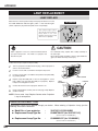
CAUTION
RISK OF ELECTRIC SHOCK
DO NOT OPEN
CAUTION :
TO REDUCE THE RISK OF ELECTRIC SHOCK, DO NOT REMOVE COVER (OR BACK). NO USERSERVICEABLE PARTS INSIDE EXCEPT LAMP REPLACEMENT. REFER SERVICING TO QUALIFIED
SERVICE PERSONNEL.
THIS SYMBOL INDICATES THAT DANGEROUS
VOLTAGE CONSTITUTING A RISK OF ELECTRIC
SHOCK IS PRESENT WITHIN THIS UNIT.
2
THIS SYMBOL INDICATES THAT THERE ARE IMPORTANT
OPERATING AND MAINTENANCE INSTRUCTIONS IN THE
USER'S MANUAL WITH THIS UNIT.
SAFETY INSTRUCTIONS
All the safety and operating instructions should be read before
the product is operated.
Read all of the instructions given here and retain them for later
use. Unplug this projector from AC power supply before
cleaning. Do not use liquid or aerosol cleaners. Use a damp
cloth for cleaning.
This projector should be operated only from the type of power
source indicated on the marking label. If you are not sure of
the type of power supplied, consult your authorized dealer or
local power company.
Follow all warnings and instructions marked on the projector.
Do not overload wall outlets and extension cords as this can
result in fire or electric shock. Do not allow anything to rest on
the power cord. Do not locate this projector where the cord
may be damaged by persons walking on it.
For added protection to the projector during a lightning storm,
or when it is left unattended and unused for long periods of
time, unplug it from the wall outlet. This will prevent damage
due to lightning and power line surges.
Do not attempt to service this projector yourself as opening or
removing covers may expose you to dangerous voltage or
other hazards. Refer all servicing to qualified service
personnel.
Do not expose this unit to rain or use near water... for
example, in a wet basement, near a swimming pool, etc...
Do not use attachments not recommended by the
manufacturer as they may cause hazards.
Do not place this projector on an unstable cart, stand, or table.
The projector may fall, causing serious injury to a child or
adult, and serious damage to the projector. Use only with a
cart or stand recommended by the manufacturer, or sold with
the projector. Wall or shelf mounting should follow the
manufacturer's instructions, and should use a mounting kit
approved by the manufacturers.
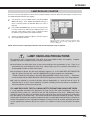
An appliance and cart combination should
be moved with care. Quick stops,
excessive force, and uneven surfaces
may cause the appliance and cart
combination to overturn.
Slots and openings in the back and bottom of the cabinet are
provided for ventilation, to insure reliable operation of the
equipment and to protect it from overheating.
Unplug this projector from wall outlet and refer servicing to
qualified service personnel under the following conditions:
a. When the power cord or plug is damaged or frayed.
b. If liquid has been spilled into the projector.
c. If the projector has been exposed to rain or water.
d. If the projector does not operate normally by following the
operating instructions. Adjust only those controls that are
covered by the operating instructions as improper
adjustment of other controls may result in damage and will
often require extensive work by a qualified technician to
restore the projector to normal operation.
e. If the projector has been dropped or the cabinet has been
damaged.
f. When the projector exhibits a distinct change in
performance-this indicates a need for service.
When replacement parts are required, be sure the service
technician has used replacement parts specified by the
manufacturer that have the same characteristics as the
original part. Unauthorized substitutions may result in fire,
electric shock, or injury to persons.
Upon completion of any service or repairs to this projector, ask
the service technician to perform routine safety checks to
determine that the projector is in safe operating condition.
The openings should never be covered with cloth or other
materials, and the bottom opening should not be blocked by
placing the projector on a bed, sofa, rug, or other similar
surface. This projector should never be placed near or over a
radiator or heat register.
This projector should not be placed in a built-in installation
such as a book case unless proper ventilation is provided.
Never push objects of any kind into this projector through
cabinet slots as they may touch dangerous voltage points or
short out parts that could result in a fire or electric shock.
Never spill liquid of any kind on the projector.
Voor de klanten in Nederland
Bij dit product zijn batterijen
geleverd.
Wanneer deze leeg zijn,
moet u ze niet weggooien
maar inleveren als KCA.
3
COMPLIANCES
Federal Communication Commission Notice
Note : This equipment has been tested and found to comply with the limits for a Class B digital device, pursuant to part
15 of the FCC Rules. These limits are designed to provide reasonable protection against harmful interference in a
residential installation. This equipment generates, uses and can radiate radio frequency energy and, if not installed and
used in accordance with the instructions, may cause harmful interference to radio communications. However, there is no
guarantee that interference will not occur in a particular installation. If this equipment does cause harmful interference to
radio or television reception, which can be determined by turning the equipment off and on, the user is encouraged to try
to correct the interference by one or more of the following measures :
– Reorient or relocate the receiving antenna.
– Increase the separation between the equipment and receiver.
– Connect the equipment into an outlet on a circuit different from that to which the receiver is connected.
– Consult the dealer or an experienced radio/TV technician for help.
Use of shielded cable is required to comply with class B limits in Subpart B of Part 15 of FCC Rules.
Do not make any changes or modifications to the equipment unless otherwise specified in the instructions. If such
changes or modifications should be made, you could be required to stop operation of the equipment.
Model Number
Trade Name
Responsible party
Address
Telephone No.
: 38-VIV211-01/103-004001
: Christie
: CHRISTIE DIGITAL SYSTEMS, Inc.
: 10550 Camden Drive Cypress, CA 90630 USA
: (714) 236-8610
AC POWER CORD REQUIREMENT
The AC Power Cord supplied with this projector meets the requirement for use in the country you purchased it.
AC Power Cord for the United States and Canada :
AC Power Cord used in the United States and Canada is listed by the Underwriters
Laboratories (UL) and certified by the Canadian Standard Association (CSA).
AC Power Cord has a grounding-type AC line plug. This is a safety feature to be sure that the
plug will fit into the power outlet. Do not try to defeat this safety feature. Should you be
unable to insert the plug into the outlet, contact your electrician.
GROUND
THE SOCKET-OUTLET SHOULD BE INSTALLED NEAR THE EQUIPMENT AND EASILY ACCESSIBLE.
4
TABLE OF CONTENTS
FEATURES AND DESIGN
PREPARATION
NAME OF EACH PART OF PROJECTOR
SETTING-UP PROJECTOR
CONNECTING AC POWER CORD
LENS INSTALLATION
POSITIONING PROJECTOR
ADJUSTABLE FEET
INSTALLING PROJECTOR IN PROPER POSITION
MOVING PROJECTOR
6
7
7
8
8
9
9
10
10
11
CONNECTING PROJECTOR
12
TERMINALS OF PROJECTOR
CONNECTING TO COMPUTER
CONNECTING TO VIDEO EQUIPMENT
12
13
14
BEFORE OPERATION
OPERATION OF REMOTE CONTROL
LASER POINTER FUNCTION
REMOTE CONTROL BATTERIES INSTALLATION
TOP CONTROLS AND INDICATORS
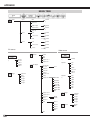
OPERATING ON-SCREEN MENU
HOW TO OPERATE ON-SCREEN MENU
FLOW OF ON-SCREEN MENU OPERATION
MENU BAR
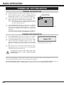
BASIC OPERATION
TURNING ON / OFF PROJECTOR
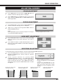
ADJUSTING SCREEN
ZOOM ADJUSTMENT
FOCUS ADJUSTMENT
LENS SHIFT ADJUSTMENT
KEYSTONE ADJUSTMENT
PICTURE FREEZE FUNCTION
NO SHOW FUNCTION
P-TIMER FUNCTION
SOUND ADJUSTMENT
15
15
15
16
17
18
18
18
19
20
20
21
21
21
21
21
22
22
22
22
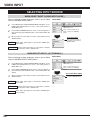
COMPUTER INPUT
SELECTING INPUT SOURCE
SELECTING COMPUTER SYSTEM
PC ADJUSTMENT
AUTO PC ADJUSTMENT
MANUAL PC ADJUSTMENT
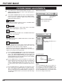
PICTURE IMAGE SELECT
IMAGE LEVEL SELECT
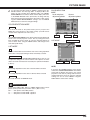
PICTURE SCREEN ADJUSTMENT
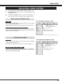
VIDEO INPUT
SELECTING INPUT SOURCE
SELECTING VIDEO SYSTEM
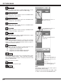
PICTURE IMAGE SELECT
IMAGE LEVEL SELECT
PICTURE SCREEN ADJUSTMENT
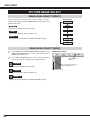
PICTURE IMAGE
PICTURE IMAGE ADJUSTMENTS
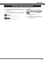
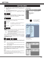
SETTING
SETTING MENU
APPENDIX
OPERATING WIRELESS MOUSE
MAINTENANCE
WARNING TEMP. INDICATOR
AIR FILTER CARE AND CLEANING
CLEANING PROJECTION LENS
LAMP REPLACEMENT
LAMP REPLACE COUNTER
TROUBLESHOOTING
INDICATORS AND PROJECTOR CONDITION
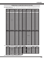
COMPATIBLE COMPUTER SPECIFICATION
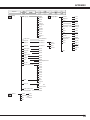
MENU TREE
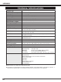
TECHNICAL SPECIFICATIONS
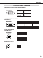
CONFIGURATIONS OF TERMINALS
OPTIONAL PARTS
LENS REPLACEMENT
23
23
23
25
25
26
28
28
29
30
30
31
32
32
33
34
34
37
37
41
41
42
42
43
43
44
45
46
48
49
50
52
53
54
54
TRADEMARKS
● Apple, Macintosh, and PowerBook are trademarks or registered trademarks of Apple Computer,Inc.
● IBM and PS/2 are trademarks or registered trademarks of International Business Machines, Inc.
● Windows and PowerPoint are registered trademarks of Microsoft Corporation.
● Each name of corporations or products in the user's manual is a trademark or a registered trademark of its
respective corporation.
5
FEATURES AND DESIGN
This Multimedia Projector is designed with most advanced technology for portability, durability, and ease of use. This
projector utilizes built-in multimedia features, a palette of 16.77 million colors, and matrix liquid crystal display (LCD)
technology.
◆
Compact Design
This projector is extremely compact in size and weight.
It is designed to carry and work anywhere you wish to
use.
◆
Compatibility
This projector widely accepts various video and
computer input signals including;
● Computers
IBM-compatible or Macintosh computer up to 1280
x 1024 resolution.
● 6 Color Systems
NTSC, PAL, SECAM, NTSC 4.43, PAL-M or PALN color system can be connected.
● Component Video
Component video signal, such as a DVD player
output high definition TV signals including 480i,
480p, 575i, 575p, 720p, 1035i or 1080i, can be
connected.
● S-Video
S-Video signal, such as a S-VHS VCR output
signal, can be connected.
◆
High Resolution Image
This projector provides 1024 x 768 dots resolution for
computer input and 800 horizontal TV lines. Resolution
from a computer between XGA (1024 x 768) and SXGA
(1280 x 1024) is compressed into 1024 x 768 dots. This
projector cannot display image of over 1280 x 1024 dots.
When resolution of your computer is over than 1280 x
1024, reset a computer output for lower resolution.
◆
Multi-Scan System
This projector has Multi-Scan System to conform to
almost all computer output signals quickly. There is no
need for troublesome manual adjustment of frequency
and other settings.
◆
One-Touch Auto PC Adjustment
Incoming computer video signals are recognized and
best adjustment is automatically set by Auto PC
Adjustment. No complicated setup is necessary and
projection is always precise.
◆
Motor-driven Lens Shift
Projection lens can be moved up and down with motordriven lens shift function. This function makes it easy to
provide projected image where you want.
Zoom and focus can be also adjusted with motor-driven
operation.
6
◆
Digital Zoom (for Computer)
Digital Zoom function adjusts image size to approx. 1/4 ~
49 times of original image size, allowing you to focus on
crucial information at a presentation.
◆
Keystone Correction
Positioning of a projector may result in distorted image
being displayed in a trapezoid shape. Keystone
Correction solves this problem by digitally altering
projection to produce undistorted images.
◆
Power Management
Power Management function is provided to reduce power
consumption while a projector is not in use.
This Power Management function operates to turn
Projection Lamp off when a projector detects signal
interruption and any button is not pressed. Projection
Lamp is automatically turned on again when a projector
detects signal or any operation button is pressed.
This projector is shipped with this function ON.
◆
Digital Visual Interface
This projector is equipped with DVI 24-pin terminal for
connecting DVI output from a computer.
◆
Laser Pointer Function
Remote Control Unit supplied with this projector includes
Laser Pointer function. This function helps you to make
a smart presentation on a projected screen.
◆
Wireless Mouse
Remote Control Unit supplied with this projector has
Wireless Mouse function for a connected computer. This
function enables you to operate both projector and
computer with Remote Control Unit only.
◆
Multilanguage Menu Display
Operation menu is displayed in; English, German,
French, Italian, Spanish, Portuguese, Dutch, Swedish,
Russian, Chinese, Korean or Japanese.
PREPARATION
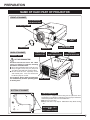
NAME OF EACH PART OF PROJECTOR
FRONT OF CABINET
TOP CONTROLS
AND INDICATORS
PROJECTION LENS
AIR INTAKE
VENT
LENS COVER
BACK OF CABINET
EXHAUST VENT
SPEAKERS
POWER CORD
CONNECTOR
INFRARED
REMOTE RECEIVER
TERMINALS
AND CONNECTORS
INFRARED
REMOTE RECEIVER
HOT AIR EXHAUSTED !
Air blown from exhaust vent is hot. When
using or installing a projector, following
precautions should be taken.
● Do not put a flammable object near this vent.
● Keep rear grills at least 3.3’(1 m) away from
any object, especially heat-sensitive object.
● Do not touch this area, especially screws
and metallic parts. This area will become
hot while a projector is used.
This projector detects internal temperature
and automatically controls operating power LAMP COVER
of Cooling Fans.
CARRYING
HANDLE
BOTTOM OF CABINET
AIR INTAKE VENTS
This projector is equipped with cooling fans for protection from
overheating. Pay attention to following to ensure proper ventilation
and avoid a possible risk of fire and malfunction.
● Do not cover vent slots.
● Keep side clear of any objects. Obstructions may block cooling
air.
ADJUSTABLE FEET
AND
FEET LOCK LATCHES
7
PREPARATION
SETTING-UP PROJECTOR
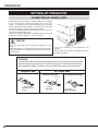
CONNECTING AC POWER CORD
This projector uses nominal input voltages of 100-120 V or 200-240
V AC. This projector automatically selects the correct input
voltage. It is designed to work with single-phase power systems
having a grounded neutral conductor. To reduce risk of electrical
shock, do not plug into any other type of power system.
Consult your authorized dealer or service station if you are not sure
of the type of power supply used.
Connect the projector with peripheral equipment before turning the
projector on. (Refer to pages 12 ~ 14 for connection.)
CAUTION
For safety, unplug AC Power Cord when an appliance is not
used.
When this projector is connected to the outlet with an AC Power
Cord, the appliance is in Stand-by Mode and consumes a little
electric power.
Connect the AC Power Cord (supplied) to the
projector.
The AC outlet must be near this equipment and must
be easily accessible.
CAUTION
The AC Power Cord must meet the requirement of the country where you use the projector.
Confirm the AC plug type with the chart below. The proper AC Power Cord must be used.
If the supplied AC Power Cord does not match the AC outlet, contact your sales dealer.
AC Outlet side
Projector side
For U.S.A. and Canada
For Continental Europe
Ground
To POWER CORD
CONNECTOR on the
projector.
8
To AC Outlet.
(120 V AC)
To AC Outlet.
(200 - 240 V AC)
PREPARATION
LENS INSTALLATION
Before setting up a projector, install Projection Lens on
Projector.
1. Before installation, check where a projector is used and
prepare a suitable lens. For specifications of a Projection
Lens, contact sales dealer where you purchased a projector.
2. For installation, refer to lens replacement and installation
manual.
NOTE;
COVER CAP
When installing the lens, remove the cover cap in the
projector.
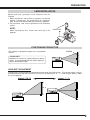
POSITIONING PROJECTOR
This projector is designed to project on a flat projection
surface.
SCREEN
ROOM LIGHT
Brightness in a room has a great influence on picture
quality. It is recommended to limit ambient lighting in
order to provide best image.
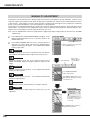
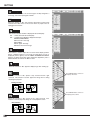
LENS SHIFT ADJUSTMENT
Projection lens can be moved up and down with motor-driven lens shift function. This function makes it easy to
provide projected image where you want. U/D ratio can be adjusted 10 : 0 ~ 1 : 1 (refer to figure below.). Refer
to P 21 for operation.
Highest (10 : 0)
Lowest (1 : 1)
1
10 : 0
1
9
PREPARATION
ADJUSTABLE FEET
Picture tilt and projection angle can be adjusted by
rotating ADJUSTABLE FEET. Projection angle can be
adjusted to 10.5 degrees.
1
Lift front of a projector and pull FEET LOCK LATCHES
on both sides of a projector.
2
Release FEET LOCK LATCHES to lock ADJUSTABLE
FEET and rotate ADJUSTABLE FEET to fine tune
position and tilt.
3
To shorten ADJUSTABLE FEET, lift front of a projector
and pull and undo FEET LOCK LATCHES.
Position and keystone distortion of image can be adjusted
using Menu Operation. (Refer to P 21 and 37.)
ADJUSTABLE FEET
FEET LOCK
LATCHES
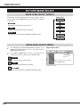
INSTALLING PROJECTOR IN PROPER POSITION
Install the projector properly. Improper installation may reduce the lamp lifetime and cause a fire hazard.
10˚
Do not tilt the projector more than 10 degrees above and below.
10˚
Do not point the projector down to project an image.
NO DOWNWARD
Do not put the projector on either side to project an image.
NO SIDEWAYS
10
PREPARATION
MOVING PROJECTOR
Use Carry Handle when moving a Projector.
When moving a projector, replace lens cover and retract
feet to prevent damage to lens and cabinet.
When this projector is not in use for an extended period,
put it into case (dust cover) supplied with this projector.
CAUTION IN CARRYING OR TRANSPORTING A PROJECTOR
● Do not drop or bump a projector, otherwise damages or malfunctions may result.
● When carrying a projector, use a suitable carrying case.
● Do not transport a projector by using a courier or transport service in an unsuitable transport case. This
may cause damage to a projector. To transport a projector through a courier or transport service, consult
your dealer for best way.
11
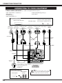
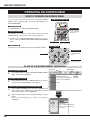
CONNECTING PROJECTOR
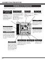
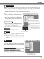
TERMINALS OF PROJECTOR
This projector has input and output terminals on its back for connecting computers and video equipment. Refer to figures on
pages 12 to 14 and connect properly.
COMPUTER AUDIO
INPUT 1/AUDIO MONITOR
OUTPUT JACK
This terminal is switchable
and can be used as computer
audio input 1 or audio monitor
output (variable).
Set the terminal up as either
Computer audio input 1 or
Audio Monitor output properly
before using this terminal.
Refer to P13, P23.)
COMPUTER INPUT/MONITOR
OUTPUT TERMINAL (ANALOG)
This terminal is switchable and
can be used as computer input or
monitor output. Set the terminal up
as either Computer input or
Monitor output properly before
using this terminal.
Refer to P13, P23.)
Note; This terminal outputs from 5
BNC type computer input on
INPUT 2 jacks only.
Connect computer output
(Digital DVI-D type) to this
terminal.
HD (HDCP Compatible) signal
can also be connected.
Refer to P13.)
INPUT 1
DIGITAL(DVI-D)
R/C JACK
USB CONNECTOR (Series B)
RESET BUTTON
This projector uses a micro processor
to control this unit, and occasionally,
this micro processor may malfunction
and need to be reset. This can be
done by pressing RESET button with a
pen, which will shut down and restart
unit. Do not use RESET function
excessively.
5 BNC INPUT JACKS
Connect component video
output (Y, Cb, Cr or Y, Pb, Pr)
from video equipment to
VIDEO/Y, Cb/Pb and Cr/Pr
jacks or connect computer
output {5 BNC Type (Green,
Blue, Red, Horiz. Sync and
Vert. Sync.)} from computer
to G, B, R, H/V and V jacks.
(Refer to P13 and 14.)
12
AUDIO 1
IN/OUT
When using Wired/Wireless
Remote Control Unit as Wired
Remote Control, Connect
Wired Remote Control Unit to
this jack with Remote Control
Cable (supplied).
CONTROL PORT
RESET
USB
Connect an audio output
(stereo) from computer to
this jack.
(Refer to P13.)
R/C JACK
ANALOG IN/OUT
When controlling computer with
Remote Control Unit of this
projector, connect USB terminal
of your personal computer to
this terminal. (Refer to P13.)
COMPUTER AUDIO
INPUT 2 JACK
COMPUTER INPUT
TERMINAL (DIGITAL)
AUDIO 2
CONTROL PORT CONNECTOR
G
B
R
VIDEO/Y
Cb/Pb
H/V
V
Cr/Pr
INPUT 2
VIDEO/Y Cb/Pb
Cr/Pr
R–AUDIO–L
(MONO)
S–VIDEO
When controlling computer
with Remote Control Unit of
this projector, connect mouse
port of your personal computer
to this connector. (Refer to
P13.)
INPUT 3
VIDEO INPUT JACKS
AUDIO INPUT JACKS
S-VIDEO INPUT JACK
Connect composite video
output from video equipment
to VIDEO/Y jack or connect
component video outputs to
VIDEO/Y, Cb/Pb and Cr/Pr
jacks. (Refer to P14.)
Connect an audio output
from video equipment to
these jacks.
(Refer to P14.)
Connect S-VIDEO
output from video
equipment to this
jack. (Refer to P14.)
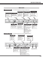
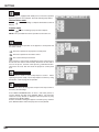
CONNECTING PROJECTOR
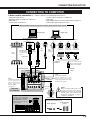
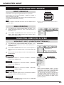
CONNECTING TO COMPUTER
Cables used for connection
(✽ = Cable or adapter is not supplied with this projector.)
• VGA Cable (HDB 15 pin)
• Control Cable for PS2 Port ✽, or ADB Port ✽
• USB Cable
• DVI-Digital Cable (for Single Link T.M.D.S.) ✽
• BNC Cable ✽
• MAC Adapter (When connecting to Macintosh computer) ✽
• Control Cable for Serial Port
• Audio Cables (Mini Plug (stereo) x 2) ✽
IBM-compatible computer or Macintosh computer (VGA / SVGA / XGA / SXGA)
Desktop type
Monitor Output
Monitor Output
or
Monitor Input
Monitor Output
MAC Adapter ✽
Set slide switches
according to chart
below.
BNC
Cable ✽
USB port
USB
Cable
DVI
Cable ✽
Laptop type
Audio Output
Audio
Cable ✽
(stereo)
ADB port
Serial port
PS/2 port
Control Cable
for Serial Port
Control Cable
for PS/2 Port ✽
Control Cable
for ADB Port ✽
Terminal
Terminal
Terminal
VGA Cable
COMPUTER
AUDIO IN 1 or 2
Use one of these Control
Cables corresponding with
terminal of your computer.
USB
COMPUTER IN ANALOG
COMPUTER IN DIGITAL
CONTROL
PORT
INPUT 1
DIGITAL(DVI-D)
ANALOG IN/OUT
NOTE;
R/C JACK
NOTE;
CONTROL PORT
RESET
USB
AUDIO 1
IN/OUT
AUDIO 2
AUDIO OUT
This terminal is switchable.
Set the terminal up as
either Computer input or
Monitor output before
using this terminal.
(See page 23.)
G
B
R
VIDEO/Y
Cb/Pb
H/V
V
This terminal is switchable.
Set the terminal up as either
Computer audio input 1 or audio
monitor output (variable) before using
this terminal. (See page 23.)
Cr/Pr
INPUT 2
VIDEO/Y Cb/Pb
Cr/Pr
S–VIDEO
R–AUDIO–L
Audio Cable
(stereo) ✽
(MONO)
Terminals
of a Projector
INPUT 3
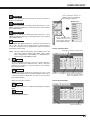
◆ MAC ADAPTER ✽
Set switches as shown in table
below depending on RESOLUTION MODE that you want to
use before you turn on projector and computer.
1
ON
13" MODE (640 x 480)
16" MODE (832 x 624) OFF
19" MODE (1024 x 768) OFF
21" MODE (1152 x 870) ON
2
ON
ON
ON
ON
NOTE :
When connecting cable, power cords
of both a projector and external
equipment should be disconnected
from AC outlet. Turn a projector and
peripheral equipment on before
computer is switched on.
Audio Input
ON
ON
External Audio Equipment
DIP
1 2 3 4 5 6
OFF
3
4
5
6
Audio Amplifier
Audio Speaker
(stereo)
OFF OFF OFF OFF
OFF ON OFF OFF
ON OFF OFF OFF
ON ON OFF OFF
13
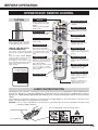
CONNECTING PROJECTOR
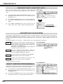
CONNECTING TO VIDEO EQUIPMENT
Cables used for connection
(✽ = Cable is not supplied with this projector.)
• Video Cable (RCA x 1 or RCA x 3) ✽
• BNC Cable ✽
• S-VIDEO Cable ✽
• Audio Cable (RCA x 2) ✽
• Audio Cable {Mini Plug (stereo)} ✽
• Scart Cable ✽
Video Source (example)
Video Cassette Recorder
Component video output equipment.
(such as DVD player or high-definition TV source.)
Video Disc Player
Composite Component Video Composite Component Video Audio Output
RGB Scart
Output
21-pin Output Video Output
Output
Video Output
(Y, Cb/Pb, Cr/Pr)
(Y, Cb/Pb, Cr/Pr)
Video Cables
(RCA x 1 or
RCA x 3) ✽
Scart Cable ✽
S-VIDEO
Output
Audio Cable
(RCA x 2) ✽
S-VIDEO
Cable ✽
BNC Cable ✽
VIDEO
Y - Cb/Pb - Cr/Pr VIDEO
Y - Cb/Pb - Cr/Pr
COMPUTER IN ANALOG
AUDIO IN
INPUT 1
DIGITAL(DVI-D)
ANALOG IN/OUT
R/C JACK
AUDIO OUT
AUDIO 1
IN/OUT
CONTROL PORT
RESET
USB
AUDIO 2
G
B
R
VIDEO/Y
Cb/Pb
H/V
V
Cr/Pr
INPUT 2
VIDEO/Y Cb/Pb
Audio Cable
(stereo) ✽
S–VIDEO
(MONO)
This terminal is switchable.
Set the terminal up as either
Computer audio input 1 or audio
monitor output (variable) before
using this terminal.
(See page 23.)
External Audio Equipment
Audio Amplifier
14
R–AUDIO–L
INPUT 3
NOTE;
Audio Input
Cr/Pr
Audio Speaker
(stereo)
Terminals
of a Projector
NOTE :
When connecting cable, power cords of
both a projector and external equipment
should be disconnected from AC outlet.
S-VIDEO
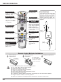
BEFORE OPERATION
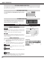
OPERATION OF REMOTE CONTROL
LASER POINTER (Drag ON)
INDICATOR
Left Side
POWER ON-OFF BUTTON
ON
Lights red while laser beam
is emitted from Laser Light
Window.
Lights green when drag ON
position. (P41)
AUTO PC ON-OFF
D.ZOOM FREEZE NO SHOW
LOCK
ALL OFF
MUTE BUTTON
Used to mute sound. (P22)
DRAG ON/OFF BUTTON
ALL-OFF SWITCH
When using Remote Control Unit,
turn this switch to “ON.” And turn it
to “ALL OFF” when it is not used.
DIP SWITCH SETTING
IMAGE
VOLUME- SELECT VOLUME+
KEYSTONE
MENU
Used to select drag ON/OFF
position. (P41)
AUTO PC ADJ. BUTTON
Use to operate AUTO PC
Adjustment function. (P25)
IMAGE BUTTON
Used to select image
level. (P28, 32)
KEYSTONE BUTTON
Used to correct keystone
distortion. (P21, 37)
LEFT CLICK BUTTON
Used as a PC mouse in
INSIDE THE BATTERY
Wireless Mouse Operation.
Press this button and the
COMPARTMENT BOX
This remote control provide the DIP mouse pointer button to drag
switches into the battery compartment a selected screen object.
(P41)
box.
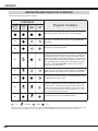
Slide the SW4 (LASER ON/OFF
switch) to "OFF" position. The laser
pointer function is not operated.
Set switches 1-3 as shown in table
below depending on Code No. that you
want to select remote control code.
(Refer to P39.)
MUTE
Used to turn projector on or
off. (P20)
MOUSE POINTER
Used as a PC mouse in
Wireless Mouse Operation.
(P41)
LASER
RIGHT CLICK BUTTON
LASER BUTTON
Used to operate Laser Pointer
Function. Laser beam is
emitted while pressing this
button within 1 minute.
When using this Laser Pointer
for more than 1 minute,
release LASER button and
press it again.
P-TIMER
INPUT 1
ZOOM COLOR.M INPUT 2
INPUT 3
FOCUS LENS
Used as a PC mouse in
Wireless Mouse Operation.
(P41)
LENS SHIFT BUTTON
Used to select LENS
SHIFT function. (P21)
SW4 ........ LASER ON/OFF
WIRED REMOTE JACK
1
2
ON
3
4
SW1 SW2 SW3 Code No.
ON
ON
ON
ON
OFF
OFF
OFF
OFF
ON
ON
OFF
OFF
ON
ON
OFF
OFF
ON
OFF
ON
OFF
ON
OFF
ON
OFF
Code 1
Code 2
Code 3
Code 4
Code 5
Code 6
Code 7
Code 8
FOCUS BUTTON
When using as Wired
Remote Control, connect
Remote Control Cable to
this jack.
Battery installation is
required when using as
Wired Remote Control.
Used to adjust focus. (P21)
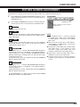
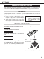
LASER POINTER FUNCTION
This Remote Control Unit emits a laser beam as laser pointer function from Laser Light Window. When LASER button is
pressed, laser light goes on. And when LASER button is being pressed for more than 1 minute or LASER button is released,
light goes off. LASER POINTER INDICATOR lights RED and Laser is emitted with RED light to indicate laser beam is being
emitted.
Laser emitted is a class II laser; therefore, do not look into Laser Light Window or shine laser beam on yourself or other
people. Three marks below are caution labels for laser beam.
CAUTION : Use of controls, adjustments or performance of procedures other than those specified herein may result
hazardous radiation exposure.
These caution labels are put on remote control.
LASER POINTER INDICATOR
Laser Light Window
15
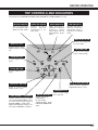
BEFORE OPERATION
NO SHOW BUTTON
D.ZOOM BUTTON
Used to select DIGITAL
ZOOM +/– mode and
resize image. (P29)
AUTO PC ON-OFF
D.ZOOM FREEZE NO SHOW
SELECT BUTTON
LOCK
Used to execute the
selected item, or to
expand or compress
image in DIGITAL ZOOM
+/- mode. (P29)
Used to turn picture into
black image. (P22)
MUTE
IMAGE
VOLUME- SELECT VOLUME+
KEYSTONE
MENU
FREEZE BUTTON
Used to freeze picture. (P22)
MENU BUTTON
INPUT 1 BUTTON
P-TIMER BUTTON
LASER
Used to operate PTIMER function. (P22)
P-TIMER
INPUT 1
ZOOM COLOR.M INPUT 2
ZOOM BUTTON
INPUT 3
Used to adjust zoom. (P21)
FOCUS LENS
Point Remote Control Unit toward
projector (Receiver Window)
whenever pressing any button.
Maximum operating range for
Remote Control Unit is about 16.4’
(5m) and 60° in front and rear of a
projector.
POINT (VOLUME +/-)
BUTTONS
Used to select an item or
adjust value in ON-SCREEN
MENU. They are also used
to pan image in DIGITAL
ZOOM +/- mode. (P29)
POINT LEFT/RIGHT buttons
are also used as VOLUME
+/- buttons. (P22)
Used to select MENU
operation. (P18, 19)
Operating Range
60°
16.4’
(5 m)
Used to select input
source (INPUT 1).
(P23)
INPUT 2 BUTTON
Used to select input
source (INPUT 2).
(P24, 30)
INPUT 3 BUTTON
16.4’
(5 m)
Used to select input
source (INPUT 3).
(P30)
COLOR MANAGEMENT
BUTTON
60°
Used to operate COLOR
MANAGEMENT.
(P34)
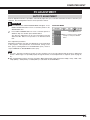
Remote Control Batteries Installation
1
Remove battery
compartment lid.
Press lid downward and slide it.
2
Slide batteries into
compartment.
3
Replace compartment lid.
Two AA size batteries
For correct polarity (+ and
–), be sure battery
terminals are in contact
with pins in compartment.
To insure safe operation, please observe following precautions :
● Use (2) AA, UM3 or R06 type alkaline batteries.
● Replace two batteries at same time.
● Do not use a new battery with an used battery.
● Avoid contact with water or liquid.
● Do not expose Remote Control Unit to moisture, or heat.
● Do not drop Remote Control Unit.
● If a battery has leaked on Remote Control Unit, carefully wipe case clean and install new batteries.
● Danger of explosion if battery is incorrectly replaced.
● Dispose of used batteries according to batteries manufacturers instructions and local rules.
16
BEFORE OPERATION
TOP CONTROLS AND INDICATORS
This projector has CONTROL BUTTONS (TOP CONTROLS) and INDICATORS on its top.
LAMP REPLACE INDICATOR
WARNING TEMP. INDICATOR
READY INDIC