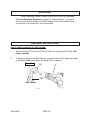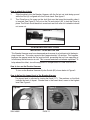
1
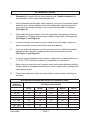
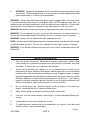
BREAKER HAMMER
Model 94882
ASSEMBLY AND OPERATING INSTRUCTIONS
Diagrams within this manual may not be drawn proportionally.
Due to continuing improvements, actual product may differ slightly from the product described herein.
Distributed exclusively by Harbor Freight Tools®.
3491 Mission Oaks Blvd., Camarillo, CA 93011
Visit our website at: http://www.harborfreight.com
Read this material before using this product.
Failure to do so can result in serious injury.
Save this manual.
Copyright© 2006 by Harbor Freight Tools®. All rights reserved. No portion of this
manual or any artwork contained herein may be reproduced in any shape or form
without the express written consent of Harbor Freight Tools.
For technical questions or replacement parts, please call 1-800-444-3353.
PRODUCT SPECIFICATIONS
Electrical Requirement
Impactor Travel
Overall Dimensions
Blows per minute
Retainer Style
Retainer Capacity
Bit hardness
Bit Dimensions:
Noise Level
Impact Energy
Tool Weight
120 Volt / 60 Hz / 16 Amps (running)
2-3/8”
25” L X 10-7/8” W X 9-3/8” H (hammer only)
1100 - 2100
Spring loaded rotational lock (2 positions only)
3/4” (19mm)
46-56 HRC
Chisel Bit: 3/4” Shank X 14-1/4” L
Bull Point Bit: 3/4” Shank X 1” W X 14-1/4” L
88 DBa @ 3 feet
3.7 to 18.4 Ft/Lbs.
33.75 Lbs.
NOTE: Plug this tool into a 20 Amp. dedicated circuit.
SAVE THIS MANUAL
You will need this manual for the safety warnings and precautions,
assembly, operating, inspection, maintenance and cleaning procedures,
parts list and assembly diagram. Keep your invoice with this manual. Write
the invoice number on the inside of the front cover. Keep this manual and
invoice in a safe and dry place for future reference.
GENERAL SAFETY RULES
WARNING!
READ AND UNDERSTAND ALL INSTRUCTIONS
Failure to follow all instructions listed below may result in
electric shock, fire, and/or serious injury.
SAVE THESE INSTRUCTIONS
WORK AREA
1.
Keep your work area clean and well lit. Cluttered benches and dark areas invite
accidents.
SKU 94882
PAGE 2
REV 07e, 08b
2.
Do not operate power tools in explosive atmospheres, such as in the presence
of flammable liquids, gases, or dust. Power tools create sparks which may ignite
the dust or fumes.
3.
Keep bystanders, children, and visitors away while operating a power tool.
Distractions can cause you to lose control. Protect others in the work area from
debris such as chips and sparks. Provide barriers or shields as needed.
ELECTRICAL SAFETY
4.
Grounded tools must be plugged into an outlet properly installed and grounded
in accordance with all codes and ordinances. Never remove the grounding
prong or modify the plug in any way. Do not use any adapter plugs. Check with
a qualified electrician if you are in doubt as to whether the outlet is properly
grounded. If the tools should electrically malfunction or break down, grounding
provides a low resistance path to carry electricity away from the user.
5.
Double insulated tools are equipped with a polarized plug (one blade is wider
than the other). This plug will fit in a polarized outlet only one way. If the plug
does not fit fully in the outlet, reverse the plug. If it still does not fit, contact
a qualified electrician to install a polarized outlet. Do not change the plug in
any way. Double insulation
eliminates the need for the three wire grounded
power cord and grounded power supply system.
6.
Avoid body contact with grounded surfaces such as pipes, radiators, ranges,
and refrigerators. There is an increased risk of electric shock if your body is
grounded.
7.
Do not expose power tools to rain or wet conditions. Water entering a
power tool will increase the risk of electric shock.
8.
Do not abuse the Power Cord. Never use the Power Cord to carry the tools
or pull the Plug from an outlet. Keep the Power Cord away from heat, oil,
sharp edges, or moving parts. Replace damaged Power Cords immediately.
Damaged Power Cords increase the risk of electric shock.
9.
When operating a power tool outside, use an outdoor extension cord marked
“W-A” or “W”. These extension cords are rated for outdoor use, and reduce the
risk of electric shock.
PERSONAL SAFETY
10.
Stay alert. Watch what you are doing, and use common sense when operating
a power tool. Do not use a power tool while tired or under the influence of
drugs, alcohol, or medication. A moment of inattention while operating power
tools may result in serious personal injury.
SKU 94882
PAGE 3
11.
Dress properly. Do not wear loose clothing or jewelry. Contain long hair.
Keep your hair, clothing, and gloves away from moving parts. Loose clothes,
jewelry, or long hair can be caught in moving parts.
12.
Avoid accidental starting. Be sure the Power Switch is off before plugging
in. Carrying power tools with your finger on the Power Switch, or plugging in power
tools with the Power Switch on, invites accidents. Make sure you are prepared to
begin work before turning the Power Switch (62) “ON”.
13.
Remove adjusting keys or wrenches before turning the power tool on. A
wrench or a key that is left attached to a rotating part of the power tool may result
in personal injury.
14.
Do not overreach. Keep proper footing and balance at all times. Proper footing
and balance enables better control of the power tool in unexpected situations.
15.
Always wear eye, hearing, and breathing protection. Wear ANSI-approved
safety impact eye glasses, ANSI-approved hearing protectors, and ANSIapproved dust mask or respirator when using this product. Also, non-skid
safety shoes and a hard hat must be used for appropriate conditions.
TOOL USE AND CARE
16.
Do not use the power tool if the Power Switch does not turn it on or off. Any
tool that cannot be controlled with the Power Switch is dangerous and must be
replaced or repaired.
17.
Disconnect the Power Cord Plug from the power source before making
any adjustments, changing accessories, or storing the tool. Such
preventive safety measures reduce the risk of starting the tool accidentally.
18.
Store idle tools out of reach of children and other untrained persons. Tools
are dangerous in the hands of untrained users.
19.
Maintain tools with care. Keep cutting tools sharp and clean. Properly
maintained tools with a sharp cutting edge are less likely to bind and are easier
to control. Do not use a damaged tool. Tag damaged tools “Do not use” until
repaired.
20.
Check for misalignment or binding of moving parts, breakage of parts, and
any other condition that may affect the tool’s operation. If damaged, have
the tool serviced before using. Many accidents are caused by poorly maintained
tools.
21.
Use only accessories that are recommended by the manufacturer for your
model. Accessories that may be suitable for one tool may become hazardous when
used on another tool.
SKU 94882
PAGE 4
SERVICE
24.
Tool service must be performed only by qualified repair personnel. Service
or maintenance performed by unqualified personnel could result in a risk of injury.
25.
When servicing a tool, use only identical replacement parts. Follow instructions
in the “Inspection, Maintenance, And Cleaning” section of this manual. Use
of unauthorized parts or failure to follow maintenance instructions may create a risk
of electric shock or injury.
GROUNDING
WARNING!
Improperly connecting the grounding wire can result in the risk of electric
shock. Check with a qualified electrician if you are in doubt as to whether the
outlet is properly grounded. Do not modify the power cord plug provided with
the tool. Never remove the grounding prong from the plug. Do not use the
tool if the power cord or plug is damaged. If damaged, have it repaired by
a service facility before use. If the plug will not fit the outlet, have a proper
outlet installed by a qualified electrician.
GROUNDED TOOLS: TOOLS WITH THREE PRONG PLUGS
1.
Tools marked with “Grounding Required” have a three wire cord and three prong
grounding plug. The plug must be connected to a properly grounded outlet. If the
tool should electrically malfunction or break down, grounding provides a low resistance path to carry electricity away from the user, reducing the risk of electric shock.
(See Figure A, next page.)
2.
The grounding prong in the plug is connected through the green wire inside the
cord to the grounding system in the tool. The green wire in the cord must be the
only wire connected to the tool’s grounding system and must never be attached to
an electrically “live” terminal. (See Figure A.)
3.
Your tool must be plugged into an appropriate outlet, properly installed and grounded
in accordance with all codes and ordinances. The plug and outlet should look like
those in the following illustration. (See Figure A page 6.)
SKU 94882
PAGE 5
FIGURE A
DOUBLE INSULATED TOOLS: TOOLS WITH TWO PRONG PLUGS
4.
5.
Tools marked “Double Insulated” do not require grounding. They have a special double insulation system which satisfies OSHA requirements and complies with the applicable standards of Underwriters Laboratories, Inc., the Canadian
Standard Association, and the National Electrical Code. (See Figure B.)
Double insulated tools may be used in either of the 120 volt outlets shown in the following illustration. (See Figure B.)
FIGURE B
SKU 94882
PAGE 6
EXTENSION CORDS
1.
Grounded tools require a three wire extension cord. Double Insulated tools can use either a two or three wire extension cord.
2.
As the distance from the supply outlet increases, you must use a heavier gauge extension cord. Using extension cords with inadequately sized wire causes a serious drop in voltage, resulting in loss of power and possible tool damage. (See Figure C)
3.
The smaller the gauge number of the wire, the greater the capacity of the cord. For example, a 14 gauge cord can carry a higher current than a 16 gauge cord. (See Figure C, and Figure D.)
4.
If using more than one extension cord to make up the total length, make sure each cord contains at least the minimum wire size required.
5.
If you are using one extension cord for more than one tool, add the nameplate
amperes and use the sum to determine the required minimum cord size.
(See Figure C, and Figure D.)
6.
If you are using an extension cord outdoors, make sure it is marked with the suffix “W-A” (“W” in Canada) to indicate it is acceptable for outdoor use.
7.
Make sure your extension cord is properly wired and in good electrical condition.
Always replace a damaged extension cord or have it repaired by a qualified electrician before using it.
8.
Protect your extension cords from sharp objects, excessive heat, and damp or
wet areas.
RECOMMENDED MINIMUM WIRE GAUGE FOR EXTENSION CORDS*
NAMEPLATE
AMPERES
(At Full Load)
EXTENSION CORD LENGTH
25 Feet
50 Feet
75 Feet
100 Feet
150 Feet
0 - 2.0
18
18
18
18
16
2.1 - 3.4
18
18
18
16
14
3.5 - 5.0
18
18
16
14
12
5.1 - 7.0
18
16
14
12
12
7.1 - 12.0
18
14
12
10
-
12.1 - 16.0
14
12
10
-
-
16.1 - 20.0
12
10
-
-
-
FIGURE C
* Based on limiting the line voltage drop to five volts at 150% of the rated amperes.
SKU 94882
PAGE 7
SYMBOLOGY
Double Insulated
Canadian Standards
Association
Underwriters
Laboratories, Inc.
V~
A
no
xxxx/min.
Volts Alternating Current
Amperes
No Load Revolutions
per Minute (RPM)
SPECIFIC SAFETY RULES
1.
Maintain labels and nameplates on the Breaker Hammer. These carry
important information. If unreadable or missing, contact Harbor Freight Tools for a
replacement.
2.
Industrial applications must follow OSHA requirements.
3.
Check for damaged parts. Before using this product, carefully check that it will
operate properly and perform its intended function. Check for damaged parts and
any other conditions that may affect the operation of this product. Replace or repair
damaged or worn parts immediately.
4.
Always disconnect the Breaker Hammer from its electrical outlet before
performing any services, maintenance, or cleaning such as leaving the work
area, moving the tool from one location to another, changing Saw Blades, cleaning
sawdust from the unit, etc.
5.
WARNING! Some dust created by power sanding, sawing, grinding, drilling, and
other construction activities, contain chemicals known (to the State of California) to
cause cancer, birth defects or other reproductive harm. Some examples of these
chemicals are:
(a) Lead from lead-based paints;
(b) Crystalline silica from bricks and cement or other masonry products;
(c) Arsenic and chromium from chemically treated lumber.
Your risk from these exposures varies, depending on how often you do this
type of work. To reduce your exposure to these chemicals; work in a well ventilated
area, and work with approved safety equipment, such as those dust masks that are
specially designed to filter out microscopic particles. (California Health & Safety
Code 25249.5, et seq.)
SKU 94882
PAGE 8
6.
WARNING! People with pacemakers should consult their physician(s) before using
this product. Electromagnetic fields in close proximity to a heart pacemaker could
cause interference to or failure of the pacemaker.
WARNING: Always wear ANSI-approved impact safety goggles. Wear a full face shield
if you are producing metal filings or wood chips. Wear an ANSI-approved dust mask or
respirator when working around metal, wood, and chemical dusts and mists. Always wear
ear protection. Ear protection is required for any other persons in the work area.
WARNING: Be aware of flying concrete chips. Keep spectators clear of the work area.
WARNING: Do not operate this tool if you have back, neck, wrist, or other conditions or
injuries that will be aggravated by the jerking forces this tool exerts upon its operator.
WARNING: Always use the side handle when operating this tool.
NOTE: Use the weight of the Breaker Hammer to break concrete. Use the tool in the vertical
position whenever possible. This tool was intended to break larger pieces of concrete.
WARNING: If the Breaker Hammer ever gets out of your control, immediately release the
Switch (62).
Vibration Hazard
This tool vibrates during use. Repeated or long-term exposure to vibration may
cause temporary or permanent physical injury, particularly to the hands, arms and
shoulders. To reduce the risk of vibration-related injury:
1.
Anyone using vibrating tools regularly or for an extended period should first be
examined by a doctor and then have regular medical check-ups to ensure medical
problems are not being caused or worsened from use. Pregnant women or people
who have impaired blood circulation to the hand, past hand injuries, nervous system
disorders, diabetes, or Raynaud’s Disease should not use this tool. If you feel any
medical or physical symptoms related to vibration (such as tingling, numbness, and
white or blue fingers), seek medical advice as soon as possible.
2.
Do not smoke during use. Nicotine reduces the blood supply to the hands and
fingers, increasing the risk of vibration-related injury.
3.
Wear suitable gloves to reduce the vibration effects on the user.
4.
Use tools with the lowest vibration when there is a choice between different processes.
5.
Include vibration-free periods each day of work.
6.
To reduce vibration, maintain the tool as explained in this manual. If any abnormal
vibration occurs, stop use immediately.
REV 07j
SKU 94882
PAGE 9
UNPACKING
When unpacking, check to make sure all parts shown on the Parts
Lists and Assembly Diagrams on pages 12-14 are included. If any parts
are missing or broken, please call Harbor Freight Tools at the number shown
on the cover of this manual as soon as possible.
ASSEMBLY INSTRUCTIONS
How to attach and adjust the Side Handle:
1.
Slide the Clamp (122) over the Collet (8). Secure it using the Knob (120). (See
Figure 1 below.)
2.
To adjust the angle of the Side Handle, loosen the Knob (120). Adjust the angle
of the Side Handle, then tighten the Knob (120) to secure it.
Figure 1
122
8
120
Side Handle
SKU 94882
PAGE 10
How to attach the chisels
1.
Slide the chisels into the Breaker Hammer with the flat cut-out side facing up and
while the Rod (4) is aligned with the Chisel shank. See figure 2.
2.
The Chisel has a flat space on the shaft that must be turned horizontally when it
is inserted. See Figure 2. Pull out on the Pin and rotate it 90° to lock the Chisel in
place. The Chisel should be able to move back and forth after it is locked but should
not come out.
Lock Pin 4
Figure 2
Chisel
OPERATING INSTRUCTIONS
Important - Read before use
This Breaker Hammer may have decreased performance for a brief period at the beginning of each use. This warm-up period lasts approximately 3-5 minutes. This happens
because the grease inside the tool may be thick, preventing the tool from operating at
full efficiency while the motor is cold. This is normal and does not indicate a problem. To
help reduce this effect, store this equipment in temperatures no lower than 50-60° F.
How to turn on the Breaker Hammer
To turn on the Breaker Hammer, flip the Switch (62) shown below in Figure 3.
How to Adjust the impact level of the Breaker Hammer
The Impact level is adjusted by turning the Knob (117). The numbers on the Knob
indicate the level of impact. Number one is the lowest level, seven is the highest
level. See Figure 4.
Figure 3
Figure 4
Knob (117)
Switch (62)
SKU 94882
PAGE 11
REV 12/06
OPERATING INSTRUCTIONS (CONTINUED)
Chipping in a straight line with a chisel bit
1.
2.
3.
4.
5.
6. Use chalk or another suitable writing material and mark you work surface to
delineate the area you intend to hammer.
Plug in the Breaker Hammer.
Grasp the main Handle (90) and side Handle (90) firmly with both hands. When you
are sure that no people or animals are in the vicinity, and it’s safe to begin, depress
the Switch (62).
The Breaker Hammer will begin to break the top layer of concrete. If you push down,
it will begin to break the next layer as well.
Keep moving the Breaker Hammer along the line you want to section, breaking
concrete as you go. If the Breaker Hammer jumps off of the line or section, release
the Switch (62) and reposition the Breaker Hammer.
When you are finished, release the Switch (62) and unplug the Breaker Hammer.
Breaking up concrete with a bull point pit
1.
2.
3.
4.
Place the bit on the center of a piece of concrete.
Grasp the main Handle (90) and side Handle (90) firmly with both hands. When you
are sure that no people or animals are in the vicinity, and it’s safe to begin, depress
the Switch Knob (87).
As you break concrete into big chunks, release the Switch Knob (87) and move to
other large pieces until all larger pieces are broken. Do not break up smaller pieces
with this tool as it is too powerful and aggressive to control on small pieces.
When finished, release the Switch Knob (87) and unplug the Breaker Hammer.
INSPECTION, MAINTENANCE, AND CLEANING
1.
2.
WARNING! Always disconnect the Breaker Hammer from its electrical power supply source before performing any inspection, maintenance, or cleaning procedure.
Before each use, inspect the general condition of the Breaker Hammer. Inspect
the switch, power plug and cord assembly, and extension cord (if used) for damage. Check for loose screws, misalignment, binding of moving parts and any other
condition that may affect its safe operation. If abnormal noise or vibration occurs,
turn off the Breaker Hammer immediately and have the problem corrected before
further use.
Do not use damaged equipment.
SKU 94882
PAGE 12
PARTS LIST
NO.
1
2
3
4
5
6
7
8
9
10
11
12
13
14
15
16
17
18
19
20
21
22
23
24
25
26
27
28
29
30
31
32
33
34
35
36
37
38
39
40
41
PART NAME
Bushing
Pin
Ring
Pin
Screw M6X40
Washer Spring Washer
Collet
O Ring
O Ring
O Ring
Spindle Cover
Seal
O Ring
Rear Bushing
Beat Piece
Bushing
Damper
Bushing
O Ring
Seal
O Ring
O Ring
Cylinder Sleeve
Ram
O Ring
Front Housing
Spring Guide
Spring
Spring Guide
Copper Guard
Spring guide
Screw M8X40
Washer
Spring Washer
Screw M4X14
Side Cover
Bearing 620NSK
Gear
Washer
Gear
QTY
1
1
1
1
6
6
6
1
1
1
1
1
1
1
1
1
1
1
1
1
1
1
1
1
1
1
1
1
2
2
1
1
4
4
4
4
2
1
1
1
1
NO.
42
43
44
45
46
47
48
49
50
51
52
53
54
55
56
57
58
59
60
61
62
63
64
65
66
67
68
69
70
71
72
73
74
75
76
77
78
79
80
81
PART NAME
Feather Key
Gear
Circlip
Bearing 6002NSK
Spacer
Spacer
Circlip
Seal
Bearing 620NSK
Circlip
Spring Washer
Washer
Screw M5X25
Cord Jacket
Cord
Capacitor
Seal
Cover
Screw ST4X18
Cord Clip
Switch
Actuator
Rod
Trigger
Pin
Brush Housing
Carbon Brush
Screw ST3X10
Brush Spring
Screw
Spring Washer
Washer
Fan Wheel
Cover
Screw ST3X10
Screw M5X25
Washer
Spring Washer
Brush Plate
Sleeve Insulator
QTY
2
1
1
2
1
1
1
1
1
1
6
6
6
1
1
1
1
1
2
1
1
1
1
1
1
2
2
2
2
1
1
1
1
1
1
4
4
4
1
1
REV 08b
SKU 94882
PAGE 13
PARTS LIST CONTINUED
NO.
82
83
84
85
86
87
88
89
90
91
92
93
94
95
96
97
98
99
100
101
102
103
104
PART NAME
Bearing 600NSK
Washer
Magnetism Ring
Rotor
Screw ST5X70
Stator
Housing
Glass Fiberpipe
Handle
Screw M5X18
Washer
Spring Washer
Screw M4X12
Cord Clip
Gear Case
O Ring
Bearing 6304NSK
Crank Shaft
Cover
Spring Washer
Washer
Screw M5X22
Needle bearing
QTY
1
1
1
1
2
1
1
1
1
6
6
6
1
1
1
1
1
1
1
3
3
3
1
NO.
105
106
107
108
109
110
111
112
113
114
115
116
117
118
119
120
121
122
123
124
125
126
127
PART NAME
QTY
Connecting Rod
1
Piston Pin
1
Pin
1
O Ring
1
Eletronic Board
1
Screw ST4X14
2
Connecting Plate
1
Cover
1
Spring Washer
5
Washer
5
Screw M5X25
5
Detent
1
Knob
1
Cover
1
Nut
1
Knob Seal
1
Handle
1
Clamp
1
Washer Clamp
2
Bolt M8X180
1
Pointed Chisel
1
Case
1
Square Chisel (not shown) 1
PLEASE READ THE FOLLOWING CAREFULLY
The manufacturer and/or distributor has provided
the parts diagram in this manual as a reference tool only.
Neither the manufacturer nor distributor makes any representation or warranty of any kind to the buyer that
he or she is qualified to make any repairs to the product
or that he or she is qualified to replace any parts of the
product. In fact, the manufacturer and/or distributor
expressly states that all repairs and parts replacements
should be undertaken by certified and licensed technicians and not by the buyer. The buyer assumes all risk and
liability arising out of his or her repairs to the original
product or replacement parts thereto, or arising out of
his or her installation of replacement parts thereto.
REV 08b
SKU 94882
PAGE 14
ASSEMBLY DIAGRAM
SKU 94882
PAGE 15
LIMITED 90 DAY WARRANTY
Harbor Freight Tools Co. makes every effort to assure that its products meet high
quality and durability standards, and warrants to the original purchaser that this product
is free from defects in materials and workmanship for the period of 90 days from the date
of purchase. This warranty does not apply to damage due directly or indirectly, to misuse,
abuse, negligence or accidents, repairs or alterations outside our facilities, criminal activity,
improper installation, normal wear and tear, or to lack of maintenance. We shall in no event
be liable for death, injuries to persons or property, or for incidental, contingent, special
or consequential damages arising from the use of our product. Some states do not allow
the exclusion or limitation of incidental or consequential damages, so the above limitation
of exclusion may not apply to you. This warranty is expressly in lieu of all
other warranties, express or implied, including the warranties of
merchantability and fitness.
To take advantage of this warranty, the product or part must be returned to us with
transportation charges prepaid. Proof of purchase date and an explanation of the complaint must accompany the merchandise. If our inspection verifies the defect, we will either
repair or replace the product at our election or we may elect to refund the purchase price
if we cannot readily and quickly provide you with a replacement. We will return repaired
products at our expense, but if we determine there is no defect, or that the defect resulted
from causes not within the scope of our warranty, then you must bear the cost of returning
the product.
This warranty gives you specific legal rights and you may also have other rights
which vary from state to state.
3491 Mission Oaks Blvd. • PO Box 6009 • Camarillo, CA 93011 • (800) 444-3353
SKU 94882
PAGE 16