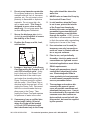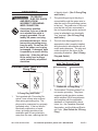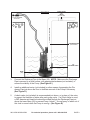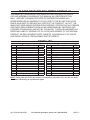
1
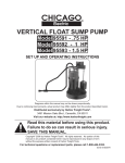
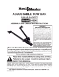
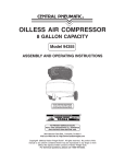
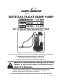
VERTICAL FLOAT SUMP PUMP
Model 95591 - .75 HP
Model 95592 - 1 HP
Model 95593 - 1.5 HP
Set up And Operating Instructions
Diagrams within this manual may not be drawn proportionally.
Due to continuing improvements, actual product may differ slightly from the product described herein.
Distributed exclusively by Harbor Freight Tools®.
3491 Mission Oaks Blvd., Camarillo, CA 93011
Visit our website at: http://www.harborfreight.com
Read this material before using this product.
Failure to do so can result in serious injury.
Save this manual.
Copyright© 2006 by Harbor Freight Tools®. All rights reserved. No portion of this
manual or any artwork contained herein may be reproduced in any shape or form
without the express written consent of Harbor Freight Tools.
For technical questions or replacement parts, please call 1-800-444-3353.
REV 07l, 08i
SPECIFICATIONS
Model 95591
Motor
115 V~ / 60 Hz / 4 A
/ 3/4 HP
Model 95592
Model 95593
115 V~ / 60 Hz / 5.5 A 115 V~ / 60 Hz / 6 A
/ 1 HP
/ 1.5 HP
Automatic Float Switch
3-Prong / Grounded
Yes
3,000 GPH
3,300 GPH
3,700 GPH
20’
24’
26’
1-1/4 NPT Female / 1-1/2 NPT Male
95° Fahrenheit
Power Switch Type
Power Plug Type
Self Priming
Maximum Pumping Capacity
Maximum Delivery Height
Discharge Diameter
Max. Operating Temperature
Performance Chart
Total Lift (feet)
30
KEY
25
Model 95591
Model 95592
Model 95593
20
15
10
5
4000
3500
3000
2500
2000
1500
1000
500
0
GPH
Note: Performance of these products will vary depending on variations in local line voltage.
SAVE THIS MANUAL
You will need this manual for the
safety warnings and precautions, assembly, operating, inspection, maintenance
and cleaning procedures, parts list and
assembly diagram. Keep your invoice with
this manual. Write the invoice number on
the inside of the front cover. Keep this
manual and invoice in a safe and dry place
for future reference.
GENERAL SAFETY RULES
WARNING! Read all instructions
Failure to follow all instructions
listed on the following pages
may result in electric shock, fire,
and/or serious injury.
SAVE THESE INSTRUCTIONS
REV 08b; 09a
SKU 95591/95592/95593
For technical questions, please call 1-800-444-3353
PAGE 2
WORK AREA
1.
Keep your work area clean and
well lit. Cluttered benches and dark
areas invite accidents.
2.
Do not operate power tools in
explosive atmospheres, such as in
the presence of flammable liquids,
gases, or dust. Power tools create
sparks which may ignite the dust or
fumes.
3.
Keep bystanders, children, and
visitors away while operating a
power tool. Distractions can cause
you to lose control. Children and
other unauthorized people should not
be allowed in the work area.
a polarized outlet. Do not change
the plug in any way. Double insulation
eliminates the need for the
three wire grounded power cord and
grounded power supply system.
3.
Avoid body contact with grounded
surfaces such as pipes, radiators,
ranges, and refrigerators. There is
an increased risk of electric shock if
your body is grounded.
4.
Do not abuse the Power Cord.
Never use the Power Cord to carry
the Sump Pump or pull the Plug
from an outlet. Keep the Power
Cord away from heat, oil, sharp
edges, or moving parts. Replace
damaged Power Cords immediately. Damaged Power Cords increase
the risk of electric shock.
ELECTRICAL SAFETY
1.
2.
Grounded tools must be plugged
into a GFCI (Ground Fault Circuit Interrupter) outlet, properly
installed, and grounded in accordance with all codes and
ordinances. Never remove the
grounding prong or modify the
plug in any way. Do not use any
adapter plugs. Check with a qualified electrician if you are in doubt
as to whether the outlet is properly
grounded. If the tools should electrically malfunction or break down,
grounding provides a low resistance
path to carry electricity away from the
user.
Double insulated tools are
equipped with a polarized plug
(one blade is wider than the other).
This plug will fit in a polarized outlet only one way. If the plug does
not fit fully in the outlet, reverse
the plug. If it still does not fit, contact a qualified electrician to install
SKU 95591/95592/95593
PERSONAL SAFETY
1.
Stay alert. Watch what you are doing, and use common sense when
operating this product. Do not use
the Sump Pump while tired or under the influence of drugs, alcohol,
or medication. A moment of inattention while operating this product may
result in serious personal injury.
2.
Dress properly. Do not wear loose
clothing or jewelry. Contain long
hair. Keep your hair, clothing, and
gloves away from moving parts.
Loose clothes, jewelry, or long hair
can be caught in moving parts.
3.
Use safety equipment. Wear ANSIapproved safety impact goggles
when assembling this product.
Non-skid safety shoes must be used
for appropriate conditions.
For technical questions, please call 1-800-444-3353
PAGE 3
TOOL USE AND CARE
1.
2.
3.
Disconnect the Power Cord Plug
from the power source before
making any adjustments, changing
accessories, or storing the Sump
Pump. Such preventive safety measures reduce the risk of starting the
unit accidentally.
Store idle equipment out of reach
of children and other untrained
persons. Electrically-powered products are dangerous in the hands of
untrained users.
Check for misalignment or binding
of moving parts, breakage of parts,
and any other condition that may
affect this product’s operation. If
damaged, have the Sump Pump
serviced before using. Many accidents are caused by poorly maintained equipment.
information. If unreadable or missing, contact Harbor Freight Tools for a
replacement.
2.
Wear ANSI-approved
safety impact eye goggles when assembling
the Pump. Using personal safety devices reduce the risk
for injury. Safety impact eye goggles
are available from Harbor Freight
Tools.
3.
Use the right product for the job.
There are certain applications for
which this product was designed. Do
not use small tools, attachments, or
equipment to do the work of larger industrial tools, attachments, or equipment.
4.
Maintain a safe environment. Keep
the area well lit. Make sure there is
adequate surrounding space. Always
keep the area free of obstructions,
grease, oil, trash, and other debris.
Do not use an electrically powered
product in areas near flammable
chemicals, dusts, and vapors.
5.
Risk of electrical shock.
Always disconnect the
Pump from its power
source before handling or
making any adjustments to the tool.
Always wear non-skid rubber boots
when water is on the floor and you
must unplug the Pump. Make sure
the electrical power source is a separately fused, grounded, 3-wire type
GFCI (Ground Fault Circuit Interrupter) outlet. Do not remove the
ground prong on the Power Cord
Plug. Do not use an extension
cord.
SERVICE
1.
2.
Service must be performed only by
qualified repair personnel. Service
or maintenance performed by unqualified personnel could result in a risk of
injury.
When servicing this product, use
only identical replacement parts.
Follow instructions in the “Inspection, Maintenance, And Cleaning”
section of this manual. Use of
unauthorized parts or failure to follow
maintenance instructions may create
a risk of electric shock or injury.
SPECIFIC SAFETY RULES
1.
Maintain labels and nameplates on
the Pump. These carry important
SKU 95591/95592/95593
For technical questions, please call 1-800-444-3353
PAGE 4
6.
Do not pump hazardous materials.
Do not pump explosive or flammable
materials such as fuel, oil, kerosene,
gasoline, etc. Do not pump in close
proximity to flammable or explosive
materials. Do not pump fats, oils,
salt or waste water. This Pump is
designed to move clean or dirty
water only. Do not pump water hotter than 95 degrees Fahrenheit.
7.
Secure the discharge pipe (not included) to a solid surface to ensure
the stability of the Pump.
8.
Position the Pump on a flat, level,
solid surface.
Drip Loop
OUTLET
CORD
Arrange a “drip loop” in the Power
Cord connecting the Pump to a 115
volt, GFCI electrical outlet. A drip
loop is that part of the Power Cord
below the level of the outlet to prevent water from traveling along the
Power Cord and coming in contact
with the outlet. If the Power Plug or
electrical outlet does get wet, do not
unplug the Power Cord. Disconnect
the fuse or circuit breaker that supplies power to the Pump. Then,
unplug the Power Cord and examine
for presence of water in the outlet.
10. If necessary, have a certified electrician install (within 10 feet of
where the Pump will be located)
a 115 volt, GFCI electrical outlet
that is dedicated only to the Pump.
SKU 95591/95592/95593
11. NEVER raise or lower the Pump by
its electrical Power Cord.
12. In cold weather, when the Pump
is not in use, protect the interior
of the Pump from freezing by
draining the water and pumping a
permanent type automobile antifreeze containing a rust inhibitor
through the system. A 50% mixture
with water is recommended. Be sure
to flush the system with a neutralizing
liquid prior to re-use of the Pump.
13. If an extension cord is used (for
temporary use only) connections
must not come in contact with water or any wet surfaces.
14. Prior to use, and periodically
thereafter, check to make sure all
connections are tight and secure.
DEVICE
9.
Any outlet should be above the
water line.
15. Industrial applications must follow
OSHA requirements.
16. People with pacemakers should
consult their physician(s) before
use. Electromagnetic fields in
close proximity to heart pacemaker could cause pacemaker interference or pacemaker failure.
17. The warnings and cautions discussed in this manual cannot
cover all possible conditions and
situations that may occur. It must
be understood by the operator that
common sense and caution are
factors which cannot be built into
this product, but must be supplied
by the operator.
For technical questions, please call 1-800-444-3353
PAGE 5
Grounding
To prevent
electric shock
and death from
incorrect grounding
wire connection:
Check with a qualified
electrician if you are in doubt
as to whether the outlet is
properly grounded. Do not
modify the power cord plug
provided with the tool. Never
remove the grounding prong
from the plug. Do not use the
tool if the power cord or plug
is damaged. If damaged, have
it repaired by a service facility
before use. If the plug will not
fit the outlet, have a proper
outlet installed by a qualified
electrician.
WARNING
of electric shock. (See 3-Prong Plug
and Outlet.)
2.
The grounding prong in the plug is
connected through the green wire inside the cord to the grounding system
in the tool. The green wire in the cord
must be the only wire connected to
the tool’s grounding system and must
never be attached to an electrically
“live” terminal. (See 3-Prong Plug
and Outlet.)
3.
The tool must be plugged into an
appropriate outlet, properly installed
and grounded in accordance with all
codes and ordinances. The plug and
outlet should look like those in the
preceding illustration. (See 3-Prong
Plug and Outlet.)
Double Insulated Tools: Tools
with Two Prong Plugs
Grounded Tools: Tools with Three
Prong Plugs
Outlets for 2-Prong Plug
1.
3-Prong Plug and Outlet
1.
Tools marked with “Grounding Required” have a three wire cord and
three prong grounding plug. The
plug must be connected to a properly
grounded outlet. If the tool should
electrically malfunction or break
down, grounding provides a low
resistance path to carry electricity
away from the user, reducing the risk
SKU 95591/95592/95593
Tools marked “Double Insulated” do
not require grounding. They have
a special double insulation system
which satisfies OSHA requirements
and complies with the applicable
standards of Underwriters Laboratories, Inc., the Canadian Standard
Association, and the National Electrical Code. (See Outlets for 2-Prong
Plug.)
For technical questions, please call 1-800-444-3353
PAGE 6
3.
4.
5.
6.
7.
As the distance from the supply outlet
increases, you must use a heavier
gauge extension cord. Using extension cords with inadequately sized
wire causes a serious drop in voltage,
resulting in loss of power and possible tool damage.
(See Table A.)
The smaller the gauge number of the
wire, the greater the capacity of the
cord. For example, a 14 gauge cord
can carry a higher current than a 16
gauge cord. (See Table A.)
RECOMMENDED MINIMUM WIRE
GAUGE FOR EXTENSION CORDS*
(120/240 VOLT)
NAMEPLATE
AMPERES
(at full load)
0 – 2.0
18
18
18
18
16
2.1 – 3.4
18
18
18
16
14
3.5 – 5.0
18
18
16
14
12
5.1 – 7.0
18
16
14
12
12
7.1 – 12.0
18
14
12
10
-
12.1 – 16.0
14
12
10
-
-
16.1 – 20.0
12
10
-
-
-
TABLE A
* Based on limiting the line
voltage drop to five volts at
150% of the rated amperes.
Symbology
When using more than one extension cord to make up the total length,
make sure each cord contains at
least the minimum wire size required.
(See Table A.)
If you are using one extension cord
for more than one tool, add the
nameplate amperes and use the sum
to determine the required minimum
cord size. (See Table A.)
If you are using an extension cord
outdoors, make sure it is marked with
the suffix “W-A” (“W” in Canada) to
indicate it is acceptable for outdoor
use.
EXTENSION CORD
LENGTH
150’
2.
Grounded tools require a three wire
extension cord. Double Insulated
tools can use either a two or three
wire extension cord.
Protect the extension cords from
sharp objects, excessive heat, and
damp or wet areas.
100’
1.
8.
75’
Extension Cords
dition. Always replace a damaged
extension cord or have it repaired by
a qualified electrician before using it.
50’
Double insulated tools may be used
in either of the 120 volt outlets shown
in the preceding illustration. (See
Outlets for 2-Prong Plug.)
25’
2.
Double Insulated
Canadian Standards Association
Underwriters Laboratories, Inc.
V~
A
Volts Alternating Current
Amperes
No Load Revolutions per Minute
n0 xxxx/min. (RPM)
Make sure the extension cord is properly wired and in good electrical con-
SKU 95591/95592/95593
For technical questions, please call 1-800-444-3353
PAGE 7
UNPACKING
When unpacking, check to make sure all the parts shown on the Parts List on
page 12 are included. If any parts are missing or broken, please call Harbor Freight
Tools at the number shown on the cover of this manual as soon as possible.
ASSEMBLY AND OPERATING INSTRUCTIONS
Note: For additional information regarding the parts listed in the following pages, refer
to the Assembly Diagram on page 13.
WARNING! Always make sure to turn off the electricity powering the Pump’s electrical outlet and that the Pump is unplugged from its outlet prior to assembling the unit, unclogging the unit, or making any adjustments to the unit.
1.
If necessary, have a certified electrician install (within 10 feet of where the Pump will be located) a 115 volt, GFCI electrical outlet that is dedicated only to the Pump.
Any outlet should be well above the water line.
2.
The discharge has both internal and external NPT threads. Use either 1-1/4” NPT
Male or 1-1/2” NPT Female PVC pipe for the discharge line. Do not use a pipe
smaller than 1-1/4”.
REV 08b
SKU 95591/95592/95593
For technical questions, please call 1-800-444-3353
PAGE 8
FIGURE E
CHECK VALVE
OR
UNION
(NOT INCLUDED)
1-1/4” OR 1-1/2” NPT PVC
TO 115 VOLT, GROUNDED
GFCI OUTLET
DISCHARGE PIPE
(NOT INCLUDED)
o
1/8”
AIR BLEED HOLE
BASE
(25)
3.
Connect the Discharge Pipe to the Base (25). NOTE: Make sure the Discharge
Pipe is secured to a solid surface, with appropriate hardware (not included), to
ensure the stability of the Pump. (See Figure E.)
4.
Install an additional union (not included) or other means of separating the Discharge Pipe just above the floor to facilitate removal of the Pump if necessary.
(See Figure E.)
5.
A check valve (not included) is recommended just above, or in place of, the union
to prevent the backflow of water after each pump cycle. If a Check Valve is used,
a 1/8” diameter air bleed hole should be drilled through the Discharge Pipe just
above the lower Base (25) to prevent Pump “airlock”. A small spray of water out of
this hole is normal while the Pump is running. (See Figure E.)
SKU 95591/95592/95593
For technical questions, please call 1-800-444-3353
PAGE 9
6.
Carefully set the Pump in place. Do not lower or raise the Pump by the Power
Cord or Discharge Pipe. (See Figure E.)
7.
The Float Switch (2) automatically switches on and off at a water depth of approximately 4 inches. The ON/OFF height can be manually changed by adjusting the
Float Switch Lock. CAUTION: Do not run the Pump dry. Doing so will increase
wear to the unit and possibly cause seal damage. (See Figure E.)
Note: This Pump has a built-in thermal protector for the Motor which automatically
shuts it off to avoid overheating. After the Motor cools, it will cycle back on. Wait
for the cycle to continue. Do not try to turn on the Pump manually after it has automatically shut off.
8.
Connect additional Discharge Pipe as needed to direct the water discharge to
the desired location. The discharge should be kept as short as possible with a
minimum number of turns. IMPORTANT: Do not exceed the maximum lift of the
Pump:
Model 95591 = 20 Feet.
Model 95592 = 24 Feet.
Model 95593 = 26 Feet.
9.
Connect the Power Cord & Plug to its 115 volt, GFCI electrical outlet, while making
sure to form a “drip loop” in the Power Cord. (See Drip Loop, page 5.)
10. When the water level exceeds approximately 4 inches the Pump will automatically
turn on and run continuously until the water level falls below 4 inches at which time
the Pump will automatically turn off.
11.
WARNING! When shutting off power to the Pump, always shut off the electrical
power to the GFCI outlet first. Then, disconnect the Pump’s Power Cord & Plug
from the GFCI outlet.
INSPECTION, MAINTENANCE, AND CLEANING
WARNING! Always shut off the electrical power to the GFCI outlet first. Then, disconnect the Pump’s Power Cord & Plug from the GFCI outlet prior to performing
any inspection, maintenance, or cleaning procedures.
1.
Before each use, inspect the general condition of the Pump. Check for cracked
or broken parts, damaged electrical wiring, clogged Impeller Cover, Impeller, Discharge Pipes, and any other condition that may affect safe operation. If abnormal
noise or vibration occurs, have the problem corrected before further use.
Do not use damaged equipment.
SKU 95591/95592/95593
For technical questions, please call 1-800-444-3353
PAGE 10
2.
To clean the Impeller Cover and Impeller: A clogged or dirty Impeller Cover
or Impeller (28) will greatly reduce performance of the Pump. To clean the Impeller Cover (31), spray the Cover with clean water. To clean the Impeller, remove
the nine Screws (32) at the bottom of the Base (25). Then, remove the Base to
expose the Impeller Cover and Impeller. Use a stream of clean water to clean the
Impeller and Impeller area inside the Pump. Then, replace the Base. (See Assy.
Diagram.)
3.
When finished, store the Pump in a clean, dry and safe location out of reach of
children. In cold weather, when the Pump is not in use, protect the interior of the
Pump from freezing by draining the water and pumping a permanent type automobile anti-freeze containing a rust inhibitor through the system. A 50% mixture with
water is recommended. Be sure to flush the system with a neutralizing liquid prior
to re-use of the Pump. Note: Always properly dispose of all used anti-freeze.
CAUTION! All maintenance, service, or repairs not mentioned in this manual
must only be performed by a qualified service technician.
TROUBLESHOOTING
Problem
Pump does not start.
No flow from the Pump.
Pump does not automatically
switch off.
Insufficient flow.
Pump switches off too soon.
SKU 95591/95592/95593
Possible Solution
1. Plug the Pump into a working, 115 volt, GFCI electrical outlet.
2. Adjust the Float Switch to a higher position.
1. Clean Impeller and Impeller Cover.
2. Check Discharge Pipe for freezing or blockage. If necessary, thaw
Pipe and/or remove excess debris.
3. Discharge Pipe excessively bent. Straighten Pipe.
1. Float Switch cannot sink down. Lower Float Switch.
2. Check for excessive debris beneath Float Switch.
3. Unplug Pump from its electrical outlet. Discontinue using Pump until
a qualified service technician checks Pump for damage.
1. Clean Impeller and Impeller Cover.
2. Check Discharge Pipe for freezing or blockage. If necessary, thaw
Pipe and/or remove excess debris. Be careful of excessive lift height.
3. Have a qualified service technician clean interior of Pump and, if
necessary, replace worn parts.
1. Adjust the Float Switch to a higher position.
2. Clean Impeller and Impeller Cover.
3. Make sure the water temperature does not exceed 95° Fahrenheit.
For technical questions, please call 1-800-444-3353
PAGE 11
PLEASE READ THE FOLLOWING CAREFULLY
THE MANUFACTURER AND/OR DISTRIBUTOR HAS PROVIDED THE PARTS
LIST AND ASSEMBLY DIAGRAM IN THIS MANUAL AS A REFERENCE TOOL
ONLY. NEITHER THE MANUFACTURER OR DISTRIBUTOR MAKES ANY
REPRESENTATION OR WARRANTY OF ANY KIND TO THE BUYER THAT HE OR
SHE IS QUALIFIED TO REPLACE ANY PARTS OF THE PRODUCT. IN FACT, THE
MANUFACTURER AND/OR DISTRIBUTOR EXPRESSLY STATES THAT ALL REPAIRS
AND PARTS REPLACEMENTS SHOULD BE UNDERTAKEN BY CERTIFIED AND
LICENSED TECHNICIANS, AND NOT BY THE BUYER. THE BUYER ASSUMES ALL
RISKS AND LIABILITY ARISING OUT OF HIS OR HER REPAIRS TO THE ORIGINAL
PRODUCT OR REPLACEMENT PARTS THERETO, OR ARISING OUT OF HIS OR
HER INSTALLATION OF REPLACEMENT PARTS THERETO.
PARTS LIST
Part
1
2
3
4
5
6
7
8
9
10
11
12
13
14
15
16
Description
Screw
Float Switch/Float Switch Lock
Screw
Screw
Back Shell
Capacitor
Cable Guide
Switch
Cable Compaction Buckle
Waterproof
Cable Compaction Board
Screw
O-Ring
Screw
Spring Washer
Ground Wire
Qty.
1
1
5
1
1
1
1
1
1
1
1
2
1
1
1
1
Part
17
18
19
20
21
22
23
24
25
26
27
28
29
30
31
32
Description
Washer
Back Cover
Stator
Bearing
Rotor
Bearing
Main Body
Oil Seal
Base
Screw
Washer
Impeller
Nut
O-Ring
Impeller Cover
Screw
Qty.
1
1
1
1
1
1
1
3
1
4
1
1
1
1
1
9
Note: Some parts are listed and shown for illustration purposes only, and are not available individually as replacement parts.
SKU 95591/95592/95593
For technical questions, please call 1-800-444-3353
PAGE 12
SKU 95591/95592/95593
32
31
30
29
28
27
26
25
24
Power Cord/Plug not shown.
23
22
19
17
11
9
7
5
3
1
Note: Some parts are listed and shown for illustration purposes
only, and are not available individually as replacement parts.
*Internal Motor Parts Are Not Consumer-Serviceable.
21
20
18
15
16
12
13
14
10
8
6
4
2
ASSEMBLY DIAGRAM
For technical questions, please call 1-800-444-3353
PAGE 13
Limited 1 year / 90 Day warranty
Harbor Freight Tools Co. makes every effort to assure that its products meet high
quality and durability standards, and warrants to the original purchaser that for a period
of ninety days from date of purchase that the engine/motor, the belts (if so equipped),
and the blades (if so equipped) are free of defects in materials and workmanship. Harbor Freight Tools also warrants to the original purchaser, for a period of one year from
date of purchase, that all other parts and components of the product are free from
defects in materials and workmanship (90 days if used by a professional contractor or
if used as rental equipment). This warranty does not apply to damage due directly or
indirectly, to misuse, abuse, negligence or accidents, repairs or alterations outside our
facilities, normal wear and tear, or to lack of maintenance. We shall in no event be liable
for death, injuries to persons or property, or for incidental, contingent, special or consequential damages arising from the use of our product. Some states do not allow the
exclusion or limitation of incidental or consequential damages, so the above limitation
of exclusion may not apply to you. This warranty is expressly in lieu of all
other warranties, express or implied, including the warranties of
merchantability and fitness.
To take advantage of this warranty, the product or part must be returned to us with
transportation charges prepaid. Proof of purchase date and an explanation of the complaint must accompany the merchandise. If our inspection verifies the defect, we will either repair or replace the product at our election or we may elect to refund the purchase
price if we cannot readily and quickly provide you with a replacement. We will return repaired products at our expense, but if we determine there is no defect, or that the defect
resulted from causes not within the scope of our warranty, then you must bear the cost
of returning the product.
This warranty gives you specific legal rights and you may also have other rights
which vary from state to state.
3491 Mission Oaks Blvd. • PO Box 6009 • Camarillo, CA 93011 • (800) 444-3353
SKU 95591/95592/95593
For technical questions, please call 1-800-444-3353
PAGE 14