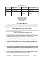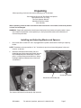
1
Concrete Slotting Saw
93009
ASSEMBLY AND OPERATING INSTRUCTIONS
3491 Mission Oaks Blvd., Camarillo, CA 93011
Visit our Web site at http://www.harborfreight.com
Copyright © 2005 by Harbor Freight Tools®. All rights reserved.
No portion of this manual or any artwork contained herein may be reproduced in any shape or form without
the express written consent of Harbor Freight Tools.
For technical questions and replacement parts, please call 1-800-444-3353
SKU 93009
For technical questions, please call 1-800-444-3353
Page 1
Specifications
Drive Construction:
Needle Bearing with
Spindle Lock
Adjustable Cutting
Dimensions:
Width .3" to 1" (8 to 26 mm)
Depth .4" to 1.18" (10 to 30 mm)
Blade
Configuration:
Adjustable Double Blade
Optional Single Blade use
Blade Size and Type:
5" Diameter Diamond
Segmented Type
Arbor Size:
7/8"
Operating Speed:
8000 RPM
Power
Requirement:
120 Volts, 60 Hz
10.5 Amps (rated), 1250 Watts
Drive Type:
Worm Gear
Net Weight:
9.80 Lbs.
Overall Dimensions: 14-1/2"L x 7"W x 7-1/2"H
Included Accessories:
Steel Chisel Point 8-1/2” Long
Two Point Spanner Wrench
Side Mount Auxiliary Handle
5mm Hex Key
Save This Manual
You will need the manual for the safety warnings and precautions, assembly instructions, operating
and maintenance procedures, parts list and diagram. Keep your invoice with this manual. Write the
invoice number on the inside of the front cover. Keep the manual and invoice in a safe and dry place for
future reference.
Safety Warnings and Precautions
WARNING: When using tool, basic safety precautions should always be followed to reduce the
risk of personal injury and damage to equipment.
Read all instructions before using this tool!
1.
Keep your work area clean and well lit. Cluttered benches and dark areas invite accidents.
2.
Do not operate power tools in explosive atmospheres, such as in the presence of flammable
liquids, gases, or dust. Power tools create sparks which may ignite the dust or fumes.
3.
Keep bystanders, children, and visitors away while operating a power tool. Distractions can
cause you to lose control. Protect others in the work area from debris such as chips and sparks.
Provide barriers or shields as needed.
4.
Grounded tools must be plugged into an outlet properly installed and grounded in accordance with all codes and ordinances. Never remove the grounding prong or modify the plug
in any way. Do not use any adapter plugs. Check with a qualified electrician if you are in
doubt whether the outlet is properly grounded. If the tool should electrically malfunction or break
down, grounding provides a low resistance path to carry electricity away from the user.
5.
Double insulated tools are equipped with a polarized plug (one blade is wider than the other).
This plug will fit in a polarized outlet only one way. If the plug does not fit fully in the outlet,
reverse the plug. If it still does not fit, contact a qualified electrician to install a polarized
outlet. Do not change the plug in any way. Double insulation eliminates the need for the three wire
grounded power cord and grounded power supply system.
6.
Avoid body contact with grounded surfaces such as pipes, radiators, ranges, and refrigerators. There is an increased risk of electric shock if your body is grounded.
SKU 93009
For technical questions, please call 1-800-444-3353
Page 2
7.
Do not expose power tools to rain or wet conditions. Water entering a power tool will increase
the risk of electric shock.
8.
Do not abuse the Power Cord. Never use the Power Cord to carry the tool or pull the Plug
from an outlet. Keep the Power Cord away from heat, oil, sharp edges, or moving parts.
Replace damaged Power Cords immediately. Damaged Power Cords increase the risk of electric shock.
9.
When operating a power tool outside, use an outdoor extension cord marked “W-A” or “W”.
These extension cords are rated for outdoor use, and reduce the risk of electric shock.
Personal Safety
10. Stay alert. Watch what you are doing, and use common sense when operating a power tool.
Do not use a power tool while tired or under the influence of drugs, alcohol, or medication. A
moment of inattention while operating power tools may result in serious personal injury.
11. Dress properly. Do not wear loose clothing or jewelry. Contain long hair. Keep your hair,
clothing, and gloves away from moving parts. Loose clothes, jewelry, or long hair can be caught
in moving parts.
12. Avoid accidental starting. Be sure the Power Switch is off before plugging in. Carrying power
tools with your hand on the Power Switch, or plugging in power tools with the Power Switch on,
invites accidents.
13. Remove adjusting keys or wrenches before turning the power tool on. A wrench or a key that is
left attached to a rotating part of the power tool may result in personal injury.
14. Do not overreach. Keep proper footing and balance at all times. Proper footing and balance
enables better control of the power tool in unexpected situations.
15. Use safety equipment. Always wear eye protection. Dust mask, non-skid safety shoes, work
gloves, hard hat, or hearing protection must be used for appropriate conditions.
Tool Use and Care
16. Do not force the tool. Use the correct tool for your application. The correct tool will do the job
better and safer at the rate for which it is designed.
17. Do not use the power tool if the Power Switch does not turn it on or off. Any tool that cannot be
controlled with the Power Switch is dangerous and must be replaced.
18. Disconnect the Power Cord Plug from the power source before making any adjustments,
changing accessories, or storing the tool. Such preventive safety measures reduce the risk of
starting the tool accidentally.
19. Store idle tools out of reach of children and other untrained persons. Tools are dangerous in
the hands of untrained users.
20. Maintain tools with care. Keep cutting tools maintained and clean. Properly maintained tools
are less likely to bind and are easier to control. Do not use a damaged tool. Tag damaged tools “Do
not use” until repaired.
SKU 93009
For technical questions, please call 1-800-444-3353
Page 3
21. Check for misalignment or binding of moving parts, breakage of parts, and any other condition that may affect the tool’s operation. If damaged, have the tool serviced before using.
Many accidents are caused by poorly maintained tools.
22. Use only accessories that are recommended by the manufacturer for your model. Accessories
that may be suitable for one tool may become hazardous when used on another tool.
Service
23. Tool service must be performed only by qualified repair personnel. Service or maintenance
performed by unqualified personnel could result in a risk of injury.
24. When servicing a tool, use only identical replacement parts. Use of unauthorized parts or failure
to follow maintenance instructions may create a risk of electric shock or injury.
Specific Safety Rules
1.
Maintain labels and nameplates on the tool. These carry important information. If unreadable or
missing, contact Harbor Freight Tools for a replacement.
2.
Always wear ANSI approved safety impact eye goggles and face mask when using the tool.
Using personal safety devices reduce the risk for injury. Safety impact eye goggles and face masks
are available from Harbor Freight Tools.
3.
Maintain a safe working environment. Keep the work area well lit. Make sure there is adequate
surrounding workspace. Always keep the work area free of obstructions, grease, oil, trash, and other
debris. Do not use a power tool in areas near flammable chemicals, dusts, and vapors. Do not use
this product in a damp or wet location.
4.
Make sure to read and understand all instructions and safety precautions as outlined in this manual.
5.
When starting a hand-held power tool, always maintain a firm grip on the tool with both hands
to resist starting torque.
6.
Always keep the extension cord away from moving parts on the tool.
7.
Avoid unintentional starting. Make sure you are prepared to begin work before turning on the tool.
8.
Do not force the tool. This tool will do the work better and safer at the speed and capacity for which
it was designed.
9.
Never lay the tool down until the motor has come to a complete stop. The tool may create
unforeseen risk while the motor cycles down.
10. Never leave the tool unattended when it is plugged into an electrical outlet. Turn off the tool,
and unplug it from its electrical outlet before leaving.
11. Always unplug the tool from its electrical outlet before performing and inspection, maintenance, or cleaning procedures.
WARNING! Some dust created by power sanding, sawing, grinding, drilling, and other construction
activities, contain chemicals known (to the State of California) to cause cancer, birth defects or other
reproductive harm. Some examples of these chemicals are: lead from lead-based paints, crystalline
silica from bricks and cement or other masonry products, arsenic and chromium from chemically
treated lumber. Your risk from these exposures varies, depending on how often you do this type of
work. To reduce your exposure to these chemicals: work in a well ventilated area, and work with
approved safety equipment, such as those dust masks that are specially designed to filter out
(California Health & Safety Code 25249.5, et seq.)
microscopic particles.
SKU 93009
For technical questions, please call 1-800-444-3353
Page 4
GROUNDING
WARNING! Improperly connecting the grounding wire can result in the risk of electric shock. Check
with a qualified electrician if you are in doubt as to whether the outlet is properly grounded. Do not modify
the power cord plug provided with the tool. Never remove the grounding prong from the plug. Do not use
the tool if the power cord or plug is damaged. If damaged, have it repaired by a service facility before use.
If the plug will not fit the outlet, have a proper outlet installed by a qualified electrician.
GROUNDED TOOLS: TOOLS WITH THREE PRONG PLUGS
1.
Tools marked with “Grounding Required” have a three wire cord and three prong grounding plug. The
plug must be connected to a properly grounded outlet. If the tool should electrically malfunction or
break down, grounding provides a low resistance path to carry electricity away from the user, reducing the risk of electric shock. (See Figure A.)
2.
The grounding prong in the plug is connected
through the green wire inside the cord to the
grounding system in the tool. The green wire in
the cord must be the only wire connected to the
tool’s grounding system and must never be
attached to an electrically “live” terminal. (See
Figure A.)
3.
Your tool must be plugged into an appropriate
outlet, properly installed and grounded in accordance with all codes and ordinances. The plug and
outlet should look like those in the following
illustration. (See Figure A.)
Figure A
DOUBLE INSULATED TOOLS: TOOLS WITH TWO PRONG PLUGS
4.
Tools marked “Double Insulated” do not require grounding. They have a special double insulation
system which satisfies OSHA requirements and complies with
the applicable standards of Underwriters Laboratories, Inc., the
Canadian Standard Association, and the National Electrical
Code. (See Figure B.)
5.
Double insulated tools may be used in either of the 120
volt outlets shown in the following illustration. (See Figure B.)
Figure B
SKU 93009
For technical questions, please call 1-800-444-3353
Page 5
EXTENSION CORDS
1.
Grounded tools require a three wire extension cord. Double Insulated tools can use either a two or
three wire extension cord.
2.
As the distance from the supply outlet increases, you must use a heavier gauge extension cord.
Using extension cords with inadequately sized wire causes a serious drop in voltage, resulting in loss
of power and possible tool damage. (See Figure C.)
3.
The smaller the gauge number of the wire, the greater the capacity of the cord. For example, a 14
gauge cord can carry a higher current than a 16 gauge cord. (See Figure C.)
4.
When using more than one extension cord to make up the total length, make sure each cord contains at least the minimum wire size required. (See Figure C.)
5.
If you are using one extension cord for more than one tool, add the nameplate amperes and use the
sum to determine the required minimum cord size. (See Figure C.)
6.
If you are using an extension cord outdoors, make sure it is marked with the suffix “W-A” (“W” in
Canada) to indicate it is acceptable for outdoor use.
7.
Make sure your extension cord is properly wired and in good electrical condition. Always replace a
damaged extension cord or have it repaired by a qualified electrician before using it.
8.
Protect your extension cords from sharp objects, excessive heat, and damp or wet areas.
Figure C.
Recommended Mimimum Wire Gauge for 120 Volt Extension Cords*
Nameplate
Extension Cord Length
Amperes (At
Full Load)
25 Feet
50 Feet
75 Feet
100 Feet
150 Feet
18
18
18
18
16
0 - 2.0
18
18
18
16
14
2.1 - 3.4
18
18
16
14
12
3.5 - 5.0
18
16
14
12
12
6.1 - 7.0
16
14
12
10
X
7.1 - 12.0
14
12
10
X
X
12.1 - 16.0
12
10
X
X
X
16.1 - 20.0
SYMBOLOGY
Double Insulated
Canadian Standards Association
Underw riters Laboratories, Inc.
V~
A
no load xxxx per min.
SKU 93009
Volts Alternating Current
Amperes
No Load Revolutions per Minute
For technical questions, please call 1-800-444-3353
Page 6
Unpacking
When unpacking, check to make sure the following parts are included.
Concrete Wall Chaser with Two Blades and Spacers
Steel Chisel Point 8-1/2” Long
Two Point Spanner Wrench
Side Mount Auxiliary Handle
5mm Hex Key
When unpacking, check to make sure that all listed accessories are included, and that the product
is intact and undamaged.
WARNING! People with pacemakers should consult their physician(s) before using this product. Operation of electrical equipment in close proximity to a heart pacemaker could cause interference or
failure of the pacemaker.
Installing and Adjusting Blades and Spacers
1.
Be sure the tool is turned OFF and is unplugged from its power source before installing or adjusting
blades.
NOTE: The blades can be spaced from .3” to 1” (8 to 26 mm) apart for various width grooves in the work
material, as desired.
2.
Remove the Blade Guard Assembly (59) and
Height Adjuster (58) by removing Screws (63 and
64) and Depth Adjuster Handle (60). Put these
parts in a safe place to prevent their loss. Swing
the Height Adjuster (58) down clear of the blade
and remove it.
Depth Adjuster Handle (60) removed
Height Adjuster (58)
Screws (63 and 64)
Blade Guard Assembly (59)
Tool shown with Blade Guard Assembly (59) removed.
SKU 93009
For technical questions, please call 1-800-444-3353
Page 7
3.
To remove the blades, hold down the Spindle Lock (89) and insert the spanner’s pins into the two holes
on the Flange Nut (57) and remove it.
4.
Remove, replace, or rearrange the blades and spacers as necessary. Important! All 6 Spacers (54
and 55) must be used at all times, otherwise the blade will not be held securely. Also, Spacer (55) has
a step designed to hold Blade (56) securely, Blade (56) must be placed on this spacer’s step, if Blade
(56) is used.
5.
Determine the desired spacing between the two blades. Be sure Clamping Flange (52) is in place on
the Spindle (43). Slide Inner Blade (53) onto the Spindle (43). Add as many Spacers (54 or 55) as
needed to create the desired spacing. Slide Outer Blade (56) onto the Spindle (43). Install any
remaining Spacers. Screw the Flange Nut (57) onto the Spindle (43) hand tight. Refer to photo below
and drawing on page 12.
Spanner (92)
6. Press in the Spindle Lock (89) to prevent the
Spindle (43) from turning. Hold it in place while
tightening the Flange Nut (57). Using the Spanner
(92) tighten the Flange Nut (57) firmly in place by
turning it clockwise on the Spindle (43). Verify that all
spacers are installed and that blade(s) are tightly
secured in place.
Spindle Lock (89)
Flange Nut (57)
7.
Replace the Blade Guard Assembly (59) and Height Adjuster (58). Tighten these in place using the
Screws (63 and 64). Replace the Depth Adjuster
Handle (60).
NOTE: The cutting depth can be adjusted from .4” to
1.18” (10 to 30 mm).
8.
To adjust the cutting depth of the blades, loosen
the Depth Adjuster Handle (60), and move the
Blade assembly up or down relative to the Blade
Guard (59). A gauge is inscribed on the Blade
Guard for your reference. Retighten the Depth
Adjuster Handle (60) before beginning work. Be
sure to test the depth and width of the cut on a
test piece before commencing work on the final
work material.
SKU 93009
Depth Adjuster Handle (60)
For technical questions, please call 1-800-444-3353
Page 8
Connecting a Dust Extraction Hose
NOTE: This tool is fitted with an outlet (73 - 76) for attaching to a dust collection system (not included).
1. Insert the hose from your dust collection system (not included) into
Connection Cap (76) and turn the Connection Cap clockwise to form a
compression seal on your hose.
NOTE: This fitting works with standard sized 2-1/2” dust collection hoses.
Your system may vary.
CAUTION: It is highly recommended that you use some type of dust collection
system, since operation of this tool creates considerable dust and debris.
WARNING: Always wear ANSI approved face shield and dust mask when
fine airborne particles of crystalline silica. Silicosis is a disabling and
sometimes fatal lung disease caused by the inhalation of fine airborne particles of crystalline silica.
Silicosis is caused by the inhalation of small particles of crystalline free silica dust. Quartz, as found
in sand or concrete, is the most common source of silicosis. Always wear a fine dust filtration mask
when working around sand, cement and other sources of airborne crystalline free silica.
Operation
NOTE: Always mark out the channels you intend to cut before beginning work. Measuring and marking
tools are available from Harbor Freight Tools.
1.
Connect the tool to an appropriate power source, and check to ensure that it is safe to begin work.
2.
Position the tool slightly above your cut mark, and place the leading edge of the Height Adjuster (58)
on the work material. Hold the Handle up, so that the cutting blades do not contact the work material.
Press the Switch (30) to turn ON the machine.
NOTE: This tool has a safety power switch. You must first press the locking button forward before
squeezing the power switch on.
3.
Slowly rotate the tool downward to “plunge” the cutting blades into the work material. Hold the tool
securely as it will want to pull away from the operator while in use.
4.
Once the Height Adjuster (58) is flush on the surface of the work material, pull the tool downward along
your cut line.
WARNING: This tool is designed to be pulled against the rotation of the blades, toward the handle end of
the tool, when in use. Do not push the tool forward when cutting.
5.
Continue to cut at a steady pace. Pay attention to the sound of the tool. If the motor speed slows
appreciably or is erratic, slow down your cutting rate. If the motor speed remains high, you can
increase your cutting rate.
WARNING: If the blades stop in mid-cut, release the trigger IMMEDIATELY. Holding the trigger while
the blades are stuck can cause permanent damage to the tool or the workpiece. Unplug the tool and
then pull the blades out of the cut. Check both blades carefully for damage and allow the motor to
cool fully before proceeding. Use less pressure and cut more slowly while continuing; this problem can
usually be prevented by cutting at the proper pace.
CAUTION: If the motor becomes overheated, a thermal safety cut out switch may engage, stopping the
tool. If you notice the tool heating up, stop work for a few minutes to allow the tool to cool. When you
continue work, use a slower cutting rate.
REV 07f
SKU 93009
For technical questions, please call 1-800-444-3353
Page 9
6.
After work is completed, release the Power Switch (30) to turn OFF the machine. Unplug the power
cord from the power source.
7.
Allow the tool to cool down before cleaning it.
8.
After the machine has cooled down, and is unplugged, clean it with a dry brush to remove cement dust
and other debris.
9.
Disconnect any Dust Extraction System you may be using.
10. Wind up the tool’s power cord, and put the tool away for safekeeping. Always store it in a dry area out
of reach of children and unauthorized persons.
Maintenance
1.
Take care in maintaining this tool. It will serve you well and for a long time if properly stored, cleaned
and maintained.
2.
Keep the tool clean, by cleaning it after each job, before storing it. During large jobs, check and clean
the tool after each hour or two of use.
3.
Periodically check the condition of the power cord to assure that it has not been damaged. If the cord
is damaged, have it repaired or replaced by a qualified service technician.
4.
Periodically check the condition of the blades. Be sure they remain sharp and are properly and tightly
installed. If a blade or spacer becomes loose, turn off the tool, unplug it from its power source, and
tighten the blade before continuing. If the blades do not cut properly, turn off and unplug the tool.
Check to be sure they are sharp and in good condition. If not, replace the blades before continuing.
5.
Always turn off the tool and unplug it from its power source whenever the tool is not in use, whenever
you service or adjust the machine, and whenever you are changing blades or accessories.
6.
If any damage is noted to this tool, repair it before continuing use. Have all repairs done by a qualified
service technician.
Troubleshooting
Problem
Possible Cause
Solution
The motor becomes hot and turns off
unexpectedly
The thermal safety cut out switch has activated.
Turn the Switch OFF, unplug the tool, and wait for
the tool to cool down. After it is cool, try restarting
the tool.
The motor has burned out or is damaged or wet.
Have the motor inspected or repaired by a
qualified service technician.
The thermal safety cut out switch has activated.
Turn the Switch OFF, unplug the tool, and wait for
the tool to cool down. After it is cool, try restarting
the tool.
The Switch is damaged.
Have the tool inspected or repaired by a qualified
service technician.
The circuit breaker in your power supply is OFF.
Check and reset the circuit breaker. Move this tool
to a circuit with greater capacity, or remove some
other appliances from the circuit.
Cutting is difficult, and the channel is irregular.
The blades are dull, loose or bent.
Unplug the tool and check the condition of the
blades. Replace if necessary.
During cutting the tool vibrates heavily.
The blades are overheated, deformed or dull.
Unplug the tool and check the condition of the
blades. Replace if necessary.
The tool runs erratically or is very noisy.
The carbon brushes are worn or cracked.
Have the tool inspected or repaired by a qualified
service technician.
The tool is OFF and will not turn on.
SKU 93009
For technical questions, please call 1-800-444-3353
Page 10
Parts List
Part
Description
Q'ty
Part
Description
Q'ty
Part
Description
Q'ty
1
Screw
4
32
Washer
1
63
Screw
2
2
Gear Box
1
33
Washer
1
64
Screw
1
3
Locking Ring
1
34
Screw
1
65
Connect Plate
1
4
Washer
1
35
Needle
1
66
Washer
1
5
Driving Gear
1
36
Locking Ring
1
67
Dust Collection Pipe
1
6
Bearing
1
37
Driven Gear
1
68
Washer
3
7
Bearing Cover
1
38
Locking Ring
1
69
Washer
3
8
Screw
2
39
Bearing
2
70
Screw
3
9
Armature
1
40
Oil Seal
1
71
Adapter
1
10
Intermediate Flange
1
41
Bearing End Plate
1
72
Seal
1
11
Stator
1
42
Key
1
73
Connector
1
12
Bearing
1
43
Spindle
1
13
Bearing Sleeve
1
44
Isolation Sleeve
1
75
Seal
1
14
Magnetic Disk
1
45
Washer
4
76
Connection Cap
1
15
Housing
1
46
Washer
4
77
Suppor t Shaft
1
16
Brush Holder
2
47
Screw
4
78
Washer
1
17
Screw
4
48
Suction Cup
1
79
Suppor t Shaft
1
18
Carbon Brush
2
49
Washer
1
80
Suppor t Roll
1
19
Electronic Element
1
50
Washer
1
81
Screw
1
20
Screw
2
51
Screw
1
82
Spring
2
21
Left Housing Cover
1
52
Clamping Flange
1
83
Guard Plate
1
22
Right Housing Cover
1
53*
Blade 125 x 22.2 x 2mm
1
84
Screw
2
23
Cable Entry Sleeve
1
54
Spacer (1)
5
85
Screw
2
24
Cable Collar
1
55
Spacer (2)
1
86
Screw
2
25
Screw
2
56*
Blade 125 x 22.2 x 2mm
1
87
Lock Ring
1
26
Screw
5
57
Flange Nut
1
88
Spring
1
27
Left Handle
1
58
Height Adjuster
1
89
Spindle Lock
1
28
Screw
3
59
Blade Guard
1
90
Cable
1
29
Right Handle
1
60
Depth Adjuster Handle
1
91
Torsion Spring
2
30
Switch
1
61
Washer
2
92
Spanner (not shown)
1
31
Side Mount Auxiliary Hand
(not shown)
*NOTE: Blade par ts 53 & 56 are identical. They are assigned different par t numbers to make the instructions clearer.
Capacitor
1
62
Washer
2
93
1
PLEASE READ THE FOLLOWING CAREFULLY
THE MANUFACTURER AND/OR DISTRIBUTOR HAS PROVIDED THE PARTS DIAGRAM IN THIS MANUAL
AS A REFERENCE TOOL ONLY. NEITHER THE MANUFACTURER NOR DISTRIBUTOR MAKES ANY REPRESENTATION OR WARRANTY OF ANY KIND TO THE BUYER THAT HE OR SHE IS QUALIFIED TO MAKE ANY
REPAIRS TO THE PRODUCT OR THAT HE OR SHE IS QUALIFIED TO REPLACE ANY PARTS OF THE PRODUCT.
IN FACT, THE MANUFACTURER AND/OR DISTRIBUTOR EXPRESSLY STATES THAT ALL REPAIRS AND PARTS
REPLACEMENTS SHOULD BE UNDERTAKEN BY CERTIFIED AND LICENSED TECHNICIANS AND NOT BY
THE BUYER. THE BUYER ASSUMES ALL RISK AND LIABILITY ARISING OUT OF HIS OR HER REPAIRS TO THE
ORIGINAL PRODUCT OR REPLACEMENT PARTS THERETO, OR ARISING OUT OF HIS OR HER INSTALLATION
OF REPLACEMENT PARTS THERETO.
REV 07f
SKU 93009
For technical questions, please call 1-800-444-3353
Page 11
Assembly Drawing
NOTE:
Some parts are listed and
shown
for
illustration
purposes only and are not
available individually as
replacement parts.
(92) Spanner (not shown)
(93) Side Mount Auxiliary Hand
(not shown)
REV 07f
SKU 93009
For technical questions, please call 1-800-444-3353
Page 12