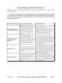
1
Electric Spray Gun Kit
44677
ASSEMBLY AND OPERATING INSTRUCTIONS
3491 Mission Oaks Blvd., Camarillo, CA 93011
Visit our Web site at http://www.harborfreight.com
Copyright © 2004 by Harbor Freight Tools®. All rights reserved.
No portion of this manual or any artwork contained herein may be reproduced in any shape or form without
the express written consent of Harbor Freight Tools.
For technical questions and replacement parts, please call 1-800-444-3353
Specifications
Power Requirement:
110V AC, 60 Hz
Air Pressure:
Constant
Paint Capacity:
1 Quar t
Electric Motor :
1-1/3 HP
Hose Specification:
15' long, 7/8" I.D.
Net Weight:
11.75 Lbs.
Air Inlet Size:
1.137"
Pre-installed Nozzle:
1.8 mm (.070")
Save This Manual
You will need the manual for the safety warnings and precautions, assembly instructions, operating
and maintenance procedures, parts list and diagram. Keep your invoice with this manual. Write the
invoice number on the inside of the front cover. Keep the manual and invoice in a safe and dry place for
future reference.
Safety Warnings and Precautions
WARNING: When using tool, basic safety precautions should always be followed to reduce the
risk of personal injury and damage to equipment.
Read all instructions before using this tool!
1.
Keep your work area clean and well lit. Cluttered benches and dark areas invite accidents.
2.
Do not operate power tool in explosive atmospheres, such as in the presence of flammable
liquids, gases, or dust. Power tools create sparks which may ignite the dust or fumes.
3.
Keep bystanders, children, and visitors away while operating a tool. Distractions can cause you
to lose control. Protect others in the work area from spray and debris such as chips and sparks.
Provide barriers or shields as needed.
4.
Grounded tools must be plugged into an outlet properly installed and grounded in accordance
with all codes and ordinances. Never remove the grounding prong or modify the plug in any
way. Do not use any adapter plugs. Check with a qualified electrician if you are in doubt
whether the outlet is properly grounded. If the tool should electrically malfunction or break down,
grounding provides a low resistance path to carry electricity away from the user.
5.
Double insulated tools are equipped with a polarized plug (one blade is wider than the other).
This plug will fit in a polarized outlet only one way. If the plug does not fit fully in the outlet,
reverse the plug. If it still does not fit, contact a qualified electrician to install a polarized
outlet. Do not change the plug in any way. Double insulation eliminates the need for the three wire
grounded power cord and grounded power supply system.
6.
Avoid body contact with grounded surfaces such as pipes, radiators, ranges, and refrigerators. There is an increased risk of electric shock if your body is grounded.
7.
Do not expose power tools to rain or wet conditions. Water entering a power tool will increase
the risk of electric shock.
8.
Do not abuse the Power Cord. Never use the Power Cord to carry the tool or pull the Plug
from an outlet. Keep the Power Cord away from heat, oil, sharp edges, or moving parts.
Replace damaged Power Cords immediately. Damaged Power Cords increase the risk of electric shock.
9.
When operating a power tool outside, use an outdoor extension cord marked “W-A” or “W”.
These extension cords are rated for outdoor use, and reduce the risk of electric shock.
REV 08/05
SKU 44677
For technical questions, please call 1-800-444-3353.
Page 2
Personal Safety
10. Stay alert. Watch what you are doing, and use common sense when operating a tool. Do not
use while tired or under the influence of drugs, alcohol, or medication. A moment of inattention
while operating power tools may result in serious personal injury or property damage.
11. Dress properly. Do not wear loose clothing or jewelry. Contain long hair. Keep your hair,
clothing, and gloves away from moving parts. Loose clothes, jewelry, or long hair can be caught
in moving parts.
12. Avoid accidental starting. Be sure the Power Switch is off before plugging in. Carrying power
tools with your finger on the Power Switch, or plugging in power tools with the Power Switch on,
invites accidents.
13. Remove adjusting keys or wrenches before turning the power tool on. A wrench or a key that is
left attached to a rotating part of the power tool may result in personal injury.
14. Do not overreach. Keep proper footing and balance at all times. Proper footing and balance
enables better control of the power tool in unexpected situations.
15. Use safety equipment. Always wear eye protection. Always wear ANSI approved safety glasses
and a full face shield. A dust mask, nonskid safety shoes, hard hat, or hearing protection must be
used for appropriate conditions.
WARNING: The brass components of this product contain lead, a chemical known to the
State of California to cause birth defects (or other reproductive harm). (California Health & Safety
code 25249.5, et seq.)
Tool Use and Care
16. Use clamps (not included) or other practical ways to secure and support the workpiece to a
stable platform. Holding the work by hand or against your body is unstable and may lead to loss of
control.
17. Do not force the tool. Use the correct tool for your application. The correct tool will do the job
better and safer at the rate for which it is designed.
18. Do not use the tool if the Power Switch does not turn it on or off. Any tool that cannot be controlled with the Power Switch is dangerous and must be replaced.
19. Disconnect the Power Cord Plug from the power source before making any adjustments,
changing accessories, or storing the tool. Such preventive safety measures reduce the risk of
starting the tool accidentally.
20. Store idle tools out of reach of children and other untrained persons. Tools are dangerous in
the hands of untrained users.
21. Maintain tools with care. Keep cutting tools maintained and clean. Properly maintained tools are
less likely to bind and are easier to control. Do not use a damaged tool. Tag damaged tools “Do not
use” until repaired.
22. Check for misalignment or binding of moving parts, breakage of parts, and any other condition
that may affect the tool’s operation. If damaged, have the tool serviced before using. Many
accidents are caused by poorly maintained tools.
23. Use only accessories that are recommended by the manufacturer for your model. Accessories
that may be suitable for one tool may become hazardous when used on another tool.
SKU 44677
For technical questions, please call 1-800-444-3353.
Page 3
Service
24. Tool service must be performed only by qualified repair personnel. Service or maintenance
performed by unqualified personnel could result in a risk of injury.
25. When servicing a tool, use only identical replacement parts. Use of unauthorized parts or failure
to follow maintenance instructions may create a risk of electric shock or injury.
Specific Safety Rules
1.
Maintain labels and nameplates on the tool. These carry important information. If unreadable or
missing, contact Harbor Freight Tools for a replacement.
2.
Always wear ANSI approved safety impact eye goggles and heavy work gloves when using the
tool. Using personal safety devices reduce the risk for injury. Safety impact eye goggles and heavy
work gloves are available from Harbor Freight Tools.
3.
Maintain a safe working environment. Keep the work area well lit. Make sure there is adequate
surrounding workspace. Always keep the work area free of obstructions, grease, oil, trash, and other
debris. Do not use a power tool in areas near flammable chemicals, dusts, and vapors. Do not use
this product in a damp or wet location.
4.
Make sure to read and understand all instructions and safety precautions as outlined in the
manufacturer’s manual of the paint or coating being used.
5.
When starting a handheld power tool, always maintain a firm grip on the tool with both hands
to resist starting torque.
6.
Always keep the extension cord away from moving parts on the tool.
7.
Avoid unintentional starting. Make sure you are prepared to begin work before turning on the tool.
8.
Do not force the tool. This tool will do the work better and safer at the speed and capacity for which
it was designed.
9.
Never leave the tool unattended when it is plugged into an electrical outlet. Turn off the tool, and
unplug it from its electrical outlet before leaving.
10. Always unplug the tool from its electrical outlet before performing and inspection, maintenance, or cleaning procedures.
11. WARNING! Some dust created by power sanding, sawing, grinding, drilling, and other construction
activities, contain chemicals known (to the State of California) to cause cancer, birth defects or other
reproductive harm. Some examples of these chemicals are: lead from lead-based paints, crystalline
silica from bricks and cement or other masonry products, arsenic and chromium from chemically
treated lumber. Your risk from these exposures varies, depending on how often you do this type of
work. To reduce your exposure to these chemicals: work in a well ventilated area, and work with
approved safety equipment, such as those dust masks that are specially designed to filter out microscopic particles. (California Health & Safety Code 25249.5, et seq.)
12. WARNING! People with pacemakers should consult their physician(s) before using this product.
Operation of electrical equipment in close proximity to a heart pacemaker could cause interference or
failure of the pacemaker.
SKU 44677
For technical questions, please call 1-800-444-3353.
Page 4
Special Warnings About Paint Sprayers
Paint sprayers can cause special hazardous situations, which you must manage in a way to prevent injury
to yourself or others.
Warning: The warnings, cautions, and instructions discussed in this instruction manual cannot
cover all possible conditions and situations that may occur. It must be understood by the operator
that common sense and caution are factors which cannot be built into this product, but must be
supplied by the operator.
SKU 44677
For technical questions, please call 1-800-444-3353.
Page 5
GROUNDING
WARNING! Improperly connecting the grounding wire can result in the risk of electric shock. Check
with a qualified electrician if you are in doubt as to whether the outlet is properly grounded. Do not modify
the power cord plug provided with the tool. Never remove the grounding prong from the plug. Do not use
the tool if the power cord or plug is damaged. If damaged, have it repaired by a service facility before use.
If the plug will not fit the outlet, have a proper outlet installed by a qualified electrician.
GROUNDED TOOLS: TOOLS WITH THREE PRONG PLUGS
1.
Tools marked with “Grounding Required” have a three wire cord and three prong grounding plug. The
plug must be connected to a properly grounded outlet. If the tool should electrically malfunction or
break down, grounding provides a low resistance
path to carry electricity away from the user, reducing the risk of electric shock. (See Figure A.)
2.
The grounding prong in the plug is connected
through the green wire inside the cord to the
grounding system in the tool. The green wire in
the cord must be the only wire connected to the
tool’s grounding system and must never be
attached to an electrically “live” terminal. (See
Figure A.)
3.
Your tool must be plugged into an appropriate
outlet, properly installed and grounded in accordance with all codes and ordinances. The plug and
outlet should look like those in the following
illustration. (See Figure A.)
Figure A
DOUBLE INSULATED TOOLS: TOOLS WITH TWO PRONG PLUGS
4.
Tools marked “Double Insulated” do not require grounding.
They have a special double insulation system which
satisfies OSHA requirements and complies with the
applicable standards of Underwriters Laboratories, Inc.,
the Canadian Standard Association, and the National
Electrical Code. (See Figure B.)
5.
Double insulated tools may be used in either of the 120
volt outlets shown in the following illustration. (See
Figure B.)
Figure B
SKU 44677
For technical questions, please call 1-800-444-3353.
Page 6
EXTENSION CORDS
1.
Grounded tools require a three wire extension cord. Double Insulated tools can use either a two or
three wire extension cord.
2.
As the distance from the supply outlet increases, you must use a heavier gauge extension cord.
Using extension cords with inadequately sized wire causes a serious drop in voltage, resulting in loss
of power and possible tool damage. (See Figure C, next page.)
3.
The smaller the gauge number of the wire, the greater the capacity of the cord. For example, a 14
gauge cord can carry a higher current than a 16 gauge cord. (See Figure C.)
4.
When using more than one extension cord to make up the total length, make sure each cord contains at least the minimum wire size required. (See Figure C.)
5.
If you are using one extension cord for more than one tool, add the nameplate amperes and use the
sum to determine the required minimum cord size. (See Figure C.)
6.
If you are using an extension cord outdoors, make sure it is marked with the suffix “W-A” (“W” in
Canada) to indicate it is acceptable for outdoor use.
7.
Make sure your extension cord is properly wired and in good electrical condition. Always replace a
damaged extension cord or have it repaired by a qualified electrician before using it.
8.
Protect your extension cords from sharp objects, excessive heat, and damp or wet areas.
Recommended Mimimum Wire Gauge for 120 Volt Extension Cords*
Nameplate
Amperes (At
Extension Cord Length
Full Load)
25 Feet
50 Feet
75 Feet
100 Feet
150 Feet
18
18
18
18
16
0 - 2.0
18
18
18
16
14
2.1 - 3.4
18
18
16
14
12
3.5 - 5.0
18
16
14
12
12
6.1 - 7.0
16
14
12
10
X
7.1 - 12.0
14
12
10
X
X
12.1 - 16.0
12
10
X
X
X
16.1 - 20.0
SYMBOLOGY
Double Insulated
Canadian Standards Association
Underw riters Laboratories, Inc.
V~
A
no load xxxx per min.
SKU 44677
Volts Alternating Current
Amperes
No Load Revolutions per Minute
For technical questions, please call 1-800-444-3353.
Page 7
Preparing to Paint
Painting Tips:
Successful spray painting is a skill which requires knowledge of your equipment, familiarity with
your paint materials and experience. Differences in paints, work materials and environmental conditions
make every painting task unique. For best results, practice with your painting mixture on a scrap piece
before beginning to paint your work material.
It is critical that the surface be properly prepared before painting. It will be difficult to achieve a
satisfactory painted surface if the original surface is dirty, rough or wet.
Properly mask your paint surface from any adjacent areas you do not want to paint.
Use drop cloths or other covers to protect adjacent property from paint dust or overspray.
Paint Mixture:
Each paint mixture will vary. You may use solvent or water based paints. Each of these causes a
different paint viscosity, and has a different flow rate and drying time. High viscosity is thick, like syrup. Low
viscosity is thin, like water.
The purpose of the solvent is to make the paint liquid so it can be applied. Once applied, the
solvent evaporates, leaving the pigment and its binders in place. The solvent is also used as a clean up
medium. Paint mixtures which are to be sprayed are generally less viscous (thinner) than mixtures which
are to be applied with a brush. Thus you will most often have to add extra solvent to a paint which is to be
sprayed.
When paint is sprayed, it is broken into tiny droplets, then blown by high-pressure air onto the
surface. During this spraying process, the surface of each paint droplet will begin to dry. When it hits the
work material, the droplet must liquefy again, and mix with the droplets hitting alongside it. Ideally, these
droplets will mix evenly forming a smooth surface.
If the paint mixture is too thick, the droplets will not form a smooth layer, and the resulting surface
can be described as “pebbly” or “orange peel”. If the paint mixture is too thin, the paint will run, forming
long drips before they are thick enough to form a satisfactory coat. Vertical surfaces are more prone to
“run” than horizontal surfaces due to the effect of gravity.
Applying the Paint:
In most cases, it is best to move the paint spray from side to side, overlapping the previous paint.
In this way you will gradually build up the paint layer without leaving any obvious edges.
To paint in this way, the spray pattern should be set to vertical.
It is important to prevent excess paint at the beginning and end of each stroke. Holding the
sprayer away from the work piece, squeeze the trigger to start the spray. Then move the spray gun in to
within 14-16 inches of the work piece. Move the sprayer smoothly across the work piece, keeping a
consistent distance. At the end of each stroke, pull the sprayer away from the work piece as you release
the trigger.
As you work, carefully observe the way the paint accumulates on the work surface. It is more
important to maintain a good paint surface than to form an opaque (thick) paint coat. You can always apply
a second coat to get the coverage you want. If the surface is ruined, however, you will have to start over
with surface preparation.
If the surface does not smooth out in a few seconds after applying the paint, your paint mixture is
probably too thick. Thin your paint slightly and test on a piece of scrap material. If the paint goes on very
thin and threatens to run, stop spraying immediately. Add more paint to your mixture to thicken the paint.
Test on a piece of scrap material before resuming work.
SKU 44677
For technical questions, please call 1-800-444-3353.
Page 8
Unpacking
When unpacking, check to make sure the following parts are included.
Electric Compressor with Spray Gun.
Air Pressure Hose
If any parts are missing or broken, please call Harbor Freight Tools at the number on the cover of this
manual.
Operation
Sprayer Controls:
To adjust the spray pattern, loosen the Lock Ring (9) by turning it counterclockwise, then rotate the
Air Cap (8), then retighten the Lock Ring (9). For a vertical spray pattern, the “ears” of the Air Cap (8) should
be horizontal. For a horizontal pattern, the “ears” should be vertical. In other words, the position of the Air
Cap and the spray pattern are at a 90° offset from one another.
To control the amount of paint mixture being sprayed, adjust the Adjusting Screw (4). Turning the
Knob clockwise will reduce the amount of paint, turning it counterclockwise will increase the amount of
paint available. CAUTION: Do not overtighten the Knob, as this will cut off the paint supply, and may
damage the Fluid Tip/Needle (7).
To change the Fluid Tip and Needle (7): The Fluid Tip and Needle (7) must both be the same size.
Check to make sure that they fit together properly before installation. Typically, a larger Tip/Needle would be
required for thicker material.
1.
Make certain that the unit is shut off, disconnected from the power supply and clean before
proceeding.
2.
Loosen and remove the Lock Ring (9), Air Cap (8), and Fluid Tip (7). Be careful not to allow any parts
to fall out of the gun.
REV 08/05
SKU 44677
For technical questions, please call 1-800-444-3353.
Page 9
3.
Remove the Fluid Adjusting Screw (4), along with the Spring (3) and Fluid Needle (7) underneath it.
Insert the desired Fluid Needle (7), and reinsert the Spring (3) and the Fluid Adjusting Screw (4).
4.
Assemble the matching Fluid Tip (7), Air Cap (8), and Lock Ring (9).
5.
The sprayer controls will require readjustment after this procedure is complete. See page 9.
Basic Function Instructions
Refer to the diagram on page 9 for these instructions:
1.
Attach the Hose to the Hose Fixture of the Main Housing, by pressing it in and turning to tighten.
2.
Attach the Hose to the Spray Gun by inserting the Hose into the fitting, and turning it to tighten.
3.
Thin the paint according to the manufacturer’s instructions. Pour the paint mixture through a cheese
cloth or paint strainer into the Spray Gun.
4.
Press the Switch to the ON position.
5.
Point the Spray Gun where desired, and squeeze the Spray Gun Trigger to begin painting.
6.
Release the Spray Gun Trigger to stop painting.
7.
Move the Switch on the Main Housing to the OFF position to turn off the compressor.
Maintenance
After each use, thoroughly clean the spray gun.
1.
Empty the Paint Cup of paint, and wipe it out with a clean rag.
2.
Fill the Paint Cup about half way with the solvent which is appropriate for the paint you have sprayed.
3.
Spray the solvent into an appropriate receptacle for proper disposal. Continue to spray until paint in
the interior of the Spray Gun is ejected and the solvent spray is clear.
NOTE: Always clean your sprayer immediately after use to avoid having to disassemble the Needle Valve
or Trigger assemblies. It is not recommended that you disassemble the paint sprayer.
4.
Using a clean rag wetted with solvent, wipe off the Spray Gun to remove paint from the exterior.
5.
Store your paint sprayer in a clean dry place out of the reach of children.
6.
All servicing of the Electric Spray Gun Kit must be performed by a qualified service technician.
PLEASE READ THE FOLLOWING CAREFULLY
THE MANUFACTURER AND/OR DISTRIBUTOR HAS PROVIDED THE PARTS DIAGRAM IN THIS MANUAL AS A REFERENCE
TOOL ONLY. NEITHER THE MANUFACTURER NOR DISTRIBUTOR MAKES ANY REPRESENTATION OR WARRANTY OF
ANY KIND TO THE BUYER THAT HE OR SHE IS QUALIFIED TO MAKE ANY REPAIRS TO THE PRODUCT OR THAT HE OR
SHE IS QUALIFIED TO REPLACE ANY PARTS OF THE PRODUCT. IN FACT, THE MANUFACTURER AND/OR DISTRIBUTOR
EXPRESSLY STATES THAT ALL REPAIRS AND PARTS REPLACEMENTS SHOULD BE UNDERTAKEN BY CERTIFIED AND
LICENSED TECHNICIANS AND NOT BY THE BUYER. THE BUYER ASSUMES ALL RISK AND LIABILITY ARISING OUT OF
HIS OR HER REPAIRS TO THE ORIGINAL PRODUCT OR REPLACEMENT PARTS THERETO, OR ARISING OUT OF HIS
OR HER INSTALLATION OF REPLACEMENT PARTS THERETO.
REV 08/05
SKU 44677
For technical questions, please call 1-800-444-3353.
Page 10
Diagram and Parts List of Spray Gun
NOTE: Some parts are listed and shown
for illustration purposes only and are
not available individually as replacement parts.
Part
Description
Qty.
Part
Description
Qty.
1
Rubber Guard
1
9
Lock Ring
1
3
Spring
1
10
Fluid Tube
1
4
Fluid Adjusting Screw
1
11
Container Gasket
1
5
Gun Body
1
12
Container
1
6
Air Flow Mandril
1
13
Fluid Needle Packing
1
7-1
Fluid Tip & Needle (1.0 mm)
1
14
Needle Packing Screw
1
7-2
Fluid Tip & Needle (1.5 mm)
1
15
Trigger
1
7-3
Fluid Tip & Needle (1.8 mm)
1
16
Trigger Pin
1
Air Cap
1
17
Nozzle Washer
1
8
REV 08/05
SKU 44677
For technical questions, please call 1-800-444-3353.
Page 11
Diagram and Parts List of Compressor
Note: When ordering parts for
the Compressor, be sure to
include the suffix “a” after the
part number.
Part
Description
Qty.
Part
Description
Qty.
1a
Main Housing (Left and Right)
1
15a
Screw
2
2a
Switch
1
16a
Housing Screw
5
3a
Motor Connector
1
17a
Filter
1
4a
Hose Fixture
1
18a
Filter Cover
1
5a
Hose
1
19a
Pointing Label
1
6a
Power Cord
1
20a
Hose Connector Pointing Label
1
7a
Tube Cover A
1
21 a
Warning Label
1
8a
Tube Cover B
1
22 a
Main Label
1
9a
Screw
2
23a
Spray Gun Set (Plastic Tank)
1
10a
Screw
2
11a
Motor
1
24a
Rubber Stand
4
12 a
Washer
3
25a
Wrench 10mm
1
13a
Screw
3
26a
Viscosity Cup
1
14a
Air Flow Tube
1
23-1a Spray Gun Set (Aluminum Tank)
1
REV 08/05
SKU 44677
For technical questions, please call 1-800-444-3353.
Page 12