1
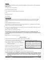
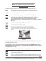
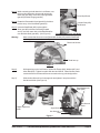
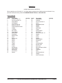
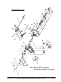
6-1/2” (18V)
CIRCULAR SAW
41903
ASSEMBLY & OPERATING INSTRUCTIONS
®
3491 Mission Oaks Blvd., Camarillo, CA 93011
Visit our Web site at http://www.harborfreight.com
Copyright© 1999 by Harbor Freight Tools®. All rights reserved. No portion of this manual or
any artwork contained herein may be reproduced in any shape or form without the express
written consent of Harbor Freight Tools.
For technical questions and replacement parts, please call 1-800-444-3353
THANK YOU for choosing a HARBOR FREIGHT TOOLS product. For future reference, please complete the
owner’s record below:
Model______________
Serial No.____________
Purchase Date__________
SAVE THE RECEIPT, WARRANTY AND THESE INSTRUCTIONS. It is important that you read the entire
manual to become familiar with the unit BEFORE you begin assembly.
Tool Name:
SKU:
Cutting Capacity:
Motor RPM:
Arbor Size:
Safety Switch:
Blade:
Max. Blade RPM:
Also Included:
Warning:
Technical Specifications
6-1/2" 18V Circular Saw
41903
2-1/16" @ 90 degrees, 1-1/2" @ 45 degrees
3,000 RPM
5/8"
2 Action
6-1/2" X 24T C-2 Tip with Hardness 89-92 HRC
7000
Quick Charger with U.L. Approved Adapter, 18V Battery, 4 mm Hex Wrench,
Blow Mold Case.
The warnings, cautions and instructions discussed in this instruction manual
cannot cover all possible conditions and situations that may occur. It must
be understood by the operator that COMMON SENSE AND CAUTION ARE
FACTORS WHICH CANNOT BE BUILT INTO THIS PRODUCT, BUT
MUST BE SUPPLIED BY THE OPERATOR.
The Operator
PLEASE REMEMBER:
Do not operate the product if under the influence of alcohol or drugs. Read warning labels on prescriptions to determine
if your judgment/reflexes might be impaired.
Do not wear loose clothing or jewelry as they can be caught in moving WARNING: Some dust created by power
parts.
sanding, sawing, grinding, drilling, and other
Protective gloves and nonskid footwear is recommended.
Wear restrictive hair covering to contain long hair.
Use eye and ear protection. Always wear ANSI approved impact
safety goggles and a dust mask or respirator when working around
metal, wood and chemical dusts and mists.
Wear a full face shield if you are producing metal or wood filings.
Maintain proper footing and balance at all times.
construction activities, contain chemicals
known [to the State of California] to cause
cancer, birth defects or other reproductive
harm. Some examples of these chemicals are:
•
Lead from lead-based paints
•
Crystalline silica from bricks and
cement or other masonry products
•
Arsenic and chromium from
chemically treated lumber
(California Health & Safety Code 25249.5, et
seq. )
Keep hands out of the cutting area and away from the blade.
Make certain that the piece being cut is properly supported; do not support the piece being cut with your hands or by
bracing with your leg.
Avoid carrying the Saw with your fingers on the Handle. Your fingers may touch the Switch and Safety trigger and start
the Saw.
REV 02/01; 10/03; 12/04; 02/05
SKU 41903
For technical questions, please call 1-800-444-3353.
Page 2
Work Area
TO AVOID RISK OF PERSONAL INJURY, EQUIPMENT DAMAGE, FIRE AND SHOCK, MAKE SURE YOUR
WORK AREA IS:
Free of damp, wet or rainy conditions.
Free of flammable gasses or liquids.
Free of children (never let them handle tools or machinery).
Well-lit.
Clean and uncluttered.
Well-ventilated.
Before Operating
Before operating your Circular Saw check for damaged parts. Before using any tool, any part that appears
damaged should be carefully checked to determine that it will operate properly and perform its intended
function.
DO NOT exceed the tools maximum capacity.
Never force the tool or attachment to do the work of a larger industrial tool. It is designed to do the job better
and more safely at the rate for which it was intended.
Do not try to use inappropriate attachments in an attempt to exceed the tool’s capacity. Approved accessories
are available from Harbor Freight Tools.
Make sure all clamps, locks and bolts are tight.
MAKE CERTAIN TO TURN OFF THE SAW, AND REMOVE THE BATTERY PACK WHEN MOVING OR
LOADING OR WHEN DOING ANY MAINTENANCE. THE TOOL SHOULD ALWAYS BE TURNED OFF WHEN
NOT IN USE.
Do not reach over or across running machines.
Battery Precautions
Read all instructions and warnings on the battery before charging the battery.
To avoid accidents, charge the supplied battery only. Do not use a different charger with this battery.
Do not expose the battery to rain or wet conditions.
To avoid damage of cable and plug, never pull the cable to
disconnect the charger.
Do not use the charger if the cable or plug are damaged.
Repairs should be carried out by experts only
Note: Always switch to a fresh battery when tool
performance begins to diminish. Severe heat is most
destructive to a battery; the more heat generated, the faster
the battery loses power. A battery that gets too hot can be
permanently damaged. Never over-discharge a battery by
using the tool even after tool performance is decreasing. Never
attempt to discharge a tool’s battery by continuing to pull the
tool trigger. When tool performance begins to diminish,
stop the tool, recharge the battery and use the fresh
battery for optimal performance.
Do not touch the battery poles with any conductive source.
Do not store the battery in a box with other metal objects.
Do not throw the battery in a fire. Ni-Cd Battery must be recycled or disposed of properly.
Note: The operation time of a new battery will ramp up as it is properly used and recharged. It will take
about 5 cycles before the battery is at maximum efficiency. Warning: If two or more batteries are to
be charged, allow the Quick Charger time to cool down between charges. Charging room temperature:
50° F - 104° F.
REV 10/03
SKU 41903
For technical questions, please call 1-800-444-3353.
Page 3
Warning: Never charge more than 2 hours continuously. Chargers
should not be left plugged in or charging for more than 2 hours.
Charging the Battery Pack
The Battery Pack (part #14) does not come charged from the factory. Charge it before using.
Step 1)
Insert the Battery Pack (#14) into the Quick Charger. The Battery Pack will only
fit in one way.
Step 2)
Plug the Quick Charger into a wall socket.
Step 3)
When the Quick Charger is plugged into a wall socket, the GREEN light will go on.
This shows that all circuitry is working properly and that the Charger is ready.
Step 4)
Press the SET button to start charging. The RED light will go on and will continue
to be on while the Battery Pack is charging. When the RED light goes off, the
Battery pack charge is complete. It will take approximately 1 to 1-1/2 hours to fully charge the
Battery Pack.
Step 5)
After charging, unplug the Quick Charger from the wall outlet.
Step 6)
Remove the Battery from the Quick Charger.
Step 7)
Insert the Battery Pack (part #14) into Saw body as shown in Figure 1.
Step 8)
When removing the Battery Pack from the Saw body, press down on the
locking tabs located on each side of the Battery Pack and pull straight out from
the body.
Figure 1-Installing the Battery Pack
Assembly
Your Circular Saw may require some assembly. Information on installation is included below for your reference.
Please refer to the photos and illustrations as well as the Assembly Diagram located on page 9 of this manual.
The Parts List is located on page 8.
It is important that you read the entire manual to become familiar with the unit BEFORE you use it. Be sure
that you have all parts described in the Parts List. For assistance with assembly please refer to the assembly
diagram and the parts list on page.
Warning:
Remove the Battery Pack (part #14) before making any adjustments to the Saw.
Installing the Cutting Blade - Note: Loosen the Hex Wrench Knob as shown in Figure 4, and remove the Hex
Wrench.
Step 1)
Remove the Battery Pack (part #14).
Step 2)
Press down on the Stop Button located on the top of the Saw while slowly moving the blade.
The tip of the Stop Button will engage in a cutout in the blade to stop the blade from moving.
REV 05/02
SKU 41903
For technical questions, please call 1-800-444-3353.
Page 4
Step 3) While continuing to hold down the Lock Button, use
the 4 mm Hex Wrench to loosen and remove the
Arbor Bolt (part #38). Remove the Spring Washer
(part #37) and the Flange (part #36).
Press Stop Button
Step 4) Rotate the Retractable Guard (part #32) clockwise
to allow entry of the Saw Blade (part #35).
Arbor Bolt (#38)
Hex Wrench
Step 5) Insert the Saw Blade (#35) up through the
Shoe (part #53) with the teeth facing forward
and up, until the center hole of the Saw Blade fits
over the Main Shaft (part #25) - (See Figure 3).
Warning:
Figure 2-Installing the Saw Blade
Make certain that the arrow on the Retractable Guard (#32) and the Saw Blade
are facing the same direction as in Figure 3.
Directional Arrows
Teeth face up
Figure 3
Step 6)
While pressing on the Lock Button, replace the Flange (#36), Washer (#37) and
Arbor Bolt (#38). Tighten into place with the Hex Wrench. When finished, make
certain that the Lock Button has been returned to the up (unlocked) position.
Step 7)
Slide the Hex Wrench into its storage slot and tighten it into place with the
Hex Wrench Knob (See Figure 4).
Bevel Adjustment
Knob (#50)
Depth Adjustment
Knob
Angle Scale
Hex Wrench
Knob
Hex Wrench
Shoe
Figure 4
SKU 41903
For technical questions, please call 1-800-444-3353.
Page 5
Adjusting the Saw Prior to Cutting
Step 1)
To adjust the angle of the Saw Blade up to 50° loosen the Bevel Adjustment
Knob (part #50) and move the Shoe (part #53) down paying attention to the
degrees indicated on the angle scale (See Figure 4). Once set, retighten the
Bevel Adjustment Knob (part #50).
Step 2)
To adjust the depth of the cut, loosen the Depth Adjustment Knob (part #7)
(See Figure 4). Move the Shoe (#53) down while observing the amount
of Saw Blade exposed under the Shoe (#53). Once adjusted, tighten the
Depth Adjustment Knob (#7).
Prepare Material Before Cutting
Step 1)
Support large panels to minimize the risk of pinching the Saw Blade and to
reduce the risk of kickback.
Step 2)
Use the Rip Fence (part #49) when ripping material.
Step 3)
Securely clamp the work piece to be cut to the workbench.
Step 4)
Make sure the Saw does not cut into the supports or the workbench.
Note:
Use the appropriate type of Saw Blade for the material you are cutting.
Operation
Before operating your Circular 6-1/2" Saw, it will be helpful to refer to each of the photos and illustrations shown
in this manual, as well as to the Parts List on page 8 and Assembly Diagram on page 9.
Cutting
Step 1)
Position the Rip Fence (part #49) to guide the Saw on a straight path.
Step 2)
With your left hand resting on the front portion of the Body (part #9/13), position your right hand
on the upper portion of the handle portion of the Body (directly above the Trigger/Safety).
Step 3)
Place the front edge of the Shoe (part #53) on the front edge of the material to be cut. Align
the front notch (right notch aligns with the Saw Blade) on the cut line.
Step 4)
Pull the Safety (part #18) back with the middle finger and squeeze the Trigger
(part #20) with the index finger. Do this before the Saw Blade touches the
work piece.
Step 5)
With the Saw at full speed, move it slowly forward to start the cut.
Step 6)
When the cut is complete, release the Trigger (part #20). Do not set the
Saw down until the Saw Blade stops turning.
SKU 41903
For technical questions, please call 1-800-444-3353.
Page 6
Maintenance
CLEANING:
Before remounting the Saw Blade, remove all sawdust that has accumulated
around the Retractable Guard (part #32) and the Spacer (part #22), Bolts and
Washers.
Regularly clean the work surface with a vacuum cleaner or a dry brush. At the end
of every work session, remove sawdust from the motor vents. Prevent wood, dust
and debris from accumulating in the working area.
Keep the Saw Blade (#35) clean and sharp. A sharp blade will minimize stalling
and kickback.
STORAGE:
Child-proof the machine and work area. Use of padlocks and master switches are
recommended. Store the Circular Saw in its Case.
IF THERE IS ANY QUESTION ABOUT A CONDITION BEING SAFE OR UNSAFE, DO NOT OPERATE THE TOOL.
PLEASE READ THE FOLLOWING CAREFULLY
THE MANUFACTURER AND/OR DISTRIBUTOR HAS PROVIDED THE PARTS DIAGRAM IN THIS
MANUAL AS A REFERENCE TOOL ONLY. NEITHER THE MANUFACTURER NOR DISTRIBUTOR
MAKES ANY REPRESENTATION OR WARRANTY OF ANY KIND TO THE BUYER THAT HE OR SHE
IS QUALIFIED TO MAKE ANY REPAIRS TO THE PRODUCT OR THAT HE OR SHE IS QUALIFIED TO
REPLACE ANY PARTS OF THE PRODUCT. IN FACT, THE MANUFACTURER AND/OR DISTRIBUTOR EXPRESSLY STATES THAT ALL REPAIRS AND PARTS REPLACEMENTS SHOULD BE UNDERTAKEN BY CERTIFIED AND LICENSED TECHNICIANS AND NOT BY THE BUYER. THE BUYER
ASSUMES ALL RISK AND LIABILITY ARISING OUT OF HIS OR HER REPAIRS TO THE ORIGINAL
PRODUCT OR REPLACEMENT PARTS THERETO, OR ARISING OUT OF HIS OR HER INSTALLATION OF REPLACEMENT PARTS THERETO.
SKU 41903
For technical questions, please call 1-800-444-3353.
Page 7
Unpacking
UNPACK AND CHECK CONTENTS
When unpacking your Circular 6-1/2", 18V Saw, check to make sure the following parts are included. If any
parts are missing or broken, please call HARBOR FREIGHT TOOLS at 1-800-444-3353.
Parts List-#41903
Part #
1
2
3
4
5
6
7
8
9
10
11
12
13
14
15
16
17
18
19
20
21
22
23
24
25
26
27
Description
Screw ST 2.9 x 25
Stud Screw M5 x 50
Snap Washer
Stud Washer
Screw ST2.9 x 19
Screw ST2.9 x 13
Depth Adjustment Knob
Washer
Left Body
Back Case
Snap Washer
Motor Base
Right Body
Battery Pack
Motor
Battery Clip
Spring
Safety
Spring
Trigger
Switch
Guard
Ball Bearing
Master Gear
Main Shaft
Stud Screw
Spacer
SKU 41903
Quantity
2
4
4
4
1
1
1
1
1
1
1
1
1
1
1
1
1
1
1
1
1
1
1
1
1
1
1
Part #
28
29
30
31
32
33
34
35
36
37
38
39
40
41
42
43
44
45
46
47
48
49
50
51
52
53
54
55
56
Description
Snap Washer
Gear Box
Stud Screw M4 x 8
Spring
Retractable Guard
Washer
Adapter
Saw Blade
Flange
Spring Washer
Arbor Bolt
Stud Screw M4 x 10
Washer
Collar
Screw
Washer
Spring Washer
Screw Cap
Plate
Connecting Bar
Bolt M6 X 80
Rip Fence
Bevel Adjustment Knob
Washer
Guard Bar
Shoe
Hex Wrench Knob
Charger
4mm Hex Wrench
For technical questions, please call 1-800-444-3353.
Quantity
1
1
1
1
1
1
1
1
1
1
1
1
1
1
1
1
1
1
1
1
1
1
1
1
1
1
1
1
1
Page 8
Assembly Diagram - 41903
38
37
36
35
34
33
49
39
32
31
30
29
28
40
42
48
41
43
44
45
50
51
54
27
26
25
46
47
24
23
22
52
53
21
20
19
18
17
13
12
15
11
10
9
16
6
5
4
3
2
14
8
7
Note: Charger (#55) is not shown.
4mm Hex Wrench (#56) is not shown.
1
SKU 41903
For technical questions, please call 1-800-444-3353.
Page 9