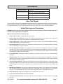
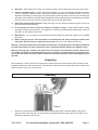
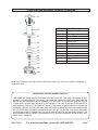
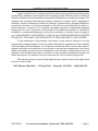
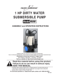
1
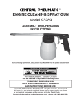
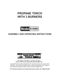
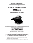
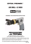
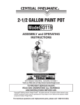
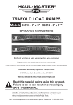
industrial air filter regulator
Model 98904
Set up and Operating Instructions
Visit our website at: http://www.harborfreight.com
Read this material before using this product.
Failure to do so can result in serious injury.
Save this manual.
Copyright© 2008 by Harbor Freight Tools®. All rights reserved. No portion of this manual or any artwork contained
herein may be reproduced in any shape or form without the express written consent of Harbor Freight Tools. Diagrams within this manual may not be drawn proportionally. Due to continuing improvements, actual product may
differ slightly from the product described herein. Tools required for assembly and service may not be included.
For technical questions or replacement parts, please call 1-800-444-3353.
Revised Manual 10c
Specifications
Operating Pressure
Air Inlet and Outlet Size
Features
0 -160 PSI
Inlet: 1/2” -14 NPT (female thread)
Outlet: 1/4”-18 NPT (male thread)
Replaceable air filter element
Filter
40 micron
Save This Manual
You will need the manual for the safety warnings and precautions, assembly instructions, operating and maintenance procedures, parts list and diagram. Keep your invoice with this manual. Write the invoice number on
the inside of the front cover. Keep the manual and invoice in a safe and dry place for future reference.
Safety Warnings and Precautions
WARNING: When using tools, basic safety precautions should always be followed to reduce the risk of
personal injury and damage to equipment.
Read all instructions before using this tool!
1.
Keep work area clean. Cluttered areas invite injuries.
2.
Observe work area conditions. Do not use in damp or wet locations. Don’t expose to rain. Keep work
area well lighted. Do not use in the presence of flammable gases or liquids.
3.
Keep children away. Children must never be allowed in the work area. Do not let them handle this product
or other machines, tools, or extension cords.
4.
Store idle equipment. When not in use, this product must be stored in a dry location to inhibit rust. Always
lock up and keep out of reach of children.
5.
Use the right tool for the job. Do not attempt to force a small tool or attachment to the work of a larger
industrial tool. There are certain applications for which this product was designed. It will do the job better
and more safely at the rate for which it was intended. Do not modify this product and do not use this product
for a purpose for which it was not intended.
6.
Do not overreach. Keep proper footing and balance at all times. Do not reach over or across running
machines.
7.
Dress properly. Do not wear loose clothing or jewelry as they can be caught in moving parts. Protective,
electrically nonconductive clothes and nonskid footwear are recommended when working. Wear restrictive
hair covering to contain long hair.
8.
Use eye and ear protection. Always wear ANSI-approved impact safety goggles when using and servicing
this product and/or air tools. Wear a full face shield if you are producing metal filings or wood chips. Wear
a NIOSH-approved dust mask or respirator when working around metal, wood, and chemical dusts and
mists.
9.
Maintain tools with care. Keep clean for better and safer performance. Follow instructions for lubricating
and changing accessories. Inspect periodically and, if damaged, have them repaired by an authorized
technician. The Filter/Regulator must be kept clean, dry, and free from oil and grease at all times.
10. Disconnect power. Unplug air compressor (not included) when not in use.
11. Do not exceed maximum air pressure of 160 PSI.
12. Avoid unintentional starting. Do not carry any air tool with your finger on the trigger, whether it is plugged
in or not.
SKU 98904
For technical questions, please call 1-800-444-3353
Page 2
13. Stay alert. Watch what you are doing, use common sense. Do not operate any tool when you are tired.
14. Check for damaged parts. Before using Filter/Regulator, any part that appears damaged should be
carefully checked to determine that it will operate properly and perform its intended function. Check for
alignment and binding of moving parts; any broken parts or mounting fixtures; and any other condition that
may affect proper operation. Any part that is damaged should be properly repaired or replaced by a qualified
technician. Do not use any air tool if its switch does not turn On and Off properly.
15. Replacement parts and accessories. When servicing, use only identical replacement parts. Use of any
other parts will void the warranty.
16. Do not operate air tools if under the influence of alcohol or drugs. Read warning labels if taking
prescription medicine to determine if your judgment or reflexes are impaired while taking drugs. If there is
any doubt, do not operate the product.
17. Maintenance. For your safety, service and maintenance should be performed regularly by a qualified
technician.
18. Before using any air tool, read and adhere to all instructions and safety warnings provided in the
instruction manual of the air compressor being used. Be sure to use compressed air only.
Warning: The brass components of this product contain lead, a chemical known to the State of California
to cause birth defects (or other reproductive harm). (California Health & Safety Code 25249.5 et seq.)
Warning: The warnings, cautions, and instructions discussed in this instruction manual cannot cover
all possible conditions and situations that may occur. It must be understood by the operator that common sense and caution are factors which cannot be built into this product, but must be supplied by the
operator.
Unpacking
When unpacking, check to make sure all parts are included. Refer to the photo below, and the Parts List and
Diagram located at the end of this manual. If any parts are missing or broken, please call Harbor Freight Tools
at the number on the cover of this manual.
Assembly
2A
1B
Figure 1
1.
Remove the contents in the small plastic bag and locate Nipple (1B). Thread the Nipple (1B) into the
side port of the Filter Cap (2A). You should use pipe thread seal tape or pipe dope (not included) on all
threaded connections. See Figure 1.
SKU 98904
For technical questions, please call 1-800-444-3353
Page 3
Assembly Continued
1B
2B
Figure 2
Figure 3
3B
2B
2.
Next thread the Air Regulator (3B) onto the Nipple (1B). See Figure 2.
3.
Thread in the Air Valve (5B) into the Air Regulator (3B). See Figure 3
1B
2B
3B
5B
Figure 5
Figure 4
1C
Figure 5
4.
Thread the Regulator Handle (1C) into the Air Regulator (3B) until tight. See Figure 4.
5.
When assembly is complete, it should look like the photo in Figure 5.
SKU 98904
For technical questions, please call 1-800-444-3353
Page 4
Air Connections
Caution: To avoid injury, make certain that the air compressor is unplugged from the power source and that all
pressure is released from its tank before connecting the Air Filter/Regulator to it.
Air Inlet
Air Hose
Male Quick Coupler
(not supplied)
Male Quick Coupler
(not supplied)
AIR COMPRESSOR
Air Hose
Regulator Handle (1C)
Pressure Gauge (6B)
(5B)
Female Quick Coupler
(not supplied)
Female Quick Coupler
(not supplied)
Air Valve (5B)
Figure 6
1.
Connect an air hose (not included) or pipe (not included) beween your air compressor (not included) and
the 1/2” air inlet located on top of the Filter Cap (2A). See Figure 6.
2.
Connect another air hose (not included) between the Air Valve (5B) and your air tool or paint gun. See
Figure 6.
NOTE: It is recommended that you use male and female quick connectors as shown in Figure 6 above. This
will allow you to quickly change air tools and hoses if requied.
Operation
1.
Turn on the air compressor and check for leaks. If any are found, turn the Compressor off, drain air from
tank, and fix the leak. WARNING: Do not exceed 160 PSI during use.
2.
With the compressor ON, turn the Regulator Handle(1C) to set the pressure that you want. Look at the
Pressure Gauge (6B) while you turn the Adjusting Screw. Stop turning the Regulator Handle (1C) when
the Pressure Gauge needle points to the desired pressure. See Figure 6.
3.
You must drain the Air Filter/Regulator of water daily. With the unit under pressure, turn the Drain Plug
(14A) to expel any accumulated moisture from the Air Filter. See page 6 parts list A.
Maintenance
Caution: To avoid injury, make certain that the Air Filter/Regulator is depressurized before performing any
maintenance on it.
1.
Periodically remove the Filter (6A), rinse it out with water and replace. If it is damaged or if it needs to be
replaced you can order a new one by calling 1-800-444-3353
2.
To disassemble the air filter; remove the Nipple (1B) from the Housing (7A) by twisting it in a
counterclockwise rotation.
3.
NOTE: You will need to firmly hold the Cap Nut (13A), with a wrench, while you turn the Nipple (1B)
because they are both connected to the same Stud (10A). See the parts list and assembly diagram page
6.
4.
Once the Nipple (1B0 is removed the filter will be accessible.
5.
Make sure to tighten the Nipple (1B) before pressurizing the unit.
SKU 98904
For technical questions, please call 1-800-444-3353
Page 5
Parts List And Assembly Diagram
7
2
2B
1B
4B
3B
5B
Part #
Description
1B
Nipple
2B
Elbow
3B
Air Regulator
4B
Plug
5B
Air Valve
6B
Gauge
6B
1A
Air inlet port
2A
3A
4A
Part #
Description
5A
1A
Plug
6A
2A
Filter Cap
3A
Gasket
7A
4A
Plug
5A
Air Valve
8A
9A
10A
6A
Filter
7A
Housing
8A
Filter Washer
9A
Retaining Ring
11A
10A
Stud
11A
Gasket
12A
Filter Base
13A
Cap Nut
14A
Drain Plug
12A
13A
14A
NOTE: Some parts are listed and shown for illustration purposes only and are not available individually as
replacement parts.
SKU 98904
For technical questions, please call 1-800-444-3353
REV 10c
Page 6
Parts List And Assembly Diagram Continued
1C
2C
Part #
Description
1C
Regulator Handle
2C
Housing Cap
3C
Spring Button
4C
Spring
5C
Spring Seat
6C
O-Ring
5C
7C
Steel Plate
6C
7C
8C
Brass Nut
9C
O-Ring
10C
Pin
11C
Spring
12C
Body
13C
Filters
3C
4C
8C
9C
10C
11C
12C
13C
NOTE: Some parts are listed and shown for illustration purposes only and are not available individually as
replacement parts.
PLEASE READ THE FOLLOWING CAREFULLY
THE MANUFACTURER AND/OR DISTRIBUTOR HAS PROVIDED THE PARTS DIAGRAM IN THIS
MANUAL AS A REFERENCE TOOL ONLY. NEITHER THE MANUFACTURER NOR DISTRIBUTOR
MAKES ANY REPRESENTATION OR WARRANTY OF ANY KIND TO THE BUYER THAT HE OR SHE
IS QUALIFIED TO MAKE ANY REPAIRS TO THE PRODUCT OR THAT HE OR SHE IS QUALIFIED TO
REPLACE ANY PARTS OF THE PRODUCT. IN FACT, THE MANUFACTURER AND/OR DISTRIBUTOR
EXPRESSLY STATES THAT ALL REPAIRS AND PARTS REPLACEMENTS SHOULD BE UNDERTAKEN
BY CERTIFIED AND LICENSED TECHNICIANS AND NOT BY THE BUYER. THE BUYER ASSUMES
ALL RISK AND LIABILITY ARISING OUT OF HIS OR HER REPAIRS TO THE ORIGINAL PRODUCT OR
REPLACEMENT PARTS THERETO, OR ARISING OUT OF HIS OR HER INSTALLATION OF REPLACEMENT PARTS THERETO.
SKU 98904
For technical questions, please call 1-800-444-3353
Page 7
LIMITED 90 DAY WARRANTY
Harbor Freight Tools Co. makes every effort to assure that its products meet high quality
and durability standards, and warrants to the original purchaser that this product is free from
defects in materials and workmanship for the period of 90 days from the date of purchase. This
warranty does not apply to damage due directly or indirectly, to misuse, abuse, negligence or
accidents, repairs or alterations outside our facilities, criminal activity, improper installation,
normal wear and tear, or to lack of maintenance. We shall in no event be liable for death, injuries to persons or property, or for incidental, contingent, special or consequential damages
arising from the use of our product. Some states do not allow the exclusion or limitation of
incidental or consequential damages, so the above limitation of exclusion may not apply to
you. This warranty is expressly in lieu of all other warranties, express
or implied, including the warranties of merchantability and fitness.
To take advantage of this warranty, the product or part must be returned to us with
transportation charges prepaid. Proof of purchase date and an explanation of the complaint
must accompany the merchandise. If our inspection verifies the defect, we will either repair or
replace the product at our election or we may elect to refund the purchase price if we cannot
readily and quickly provide you with a replacement. We will return repaired products at our
expense, but if we determine there is no defect, or that the defect resulted from causes not
within the scope of our warranty, then you must bear the cost of returning the product.
This warranty gives you specific legal rights and you may also have other rights which
vary from state to state.
3491 Mission Oaks Blvd. • PO Box 6009 • Camarillo, CA 93011 • (800) 444-3353
SKU 98904
For technical questions, please call 1-800-444-3353
Page 8