1
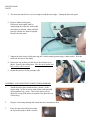
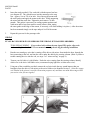
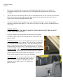
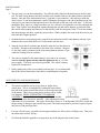
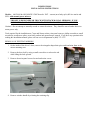
POWER VISION
INSTALLATION INSTRUCTIONS
Models: 6405/4410 & 6405/4410TK GM/Chevrolet 2007 – current (new body style) full size trucks and
SUVs with manual power mirrors.
THIS SET IS DESIGNED FOR TRUCK WITH STOCK MANUAL MIRRORS. IF YOU
CURRENTLY HAVE POWER MIRRORS, THE WRONG SET HAS BEEN ORDERED.
Caution! - Do not attempt to manually extend or retract the mirrors. They should be moved under their own
motor power only.
Tools required for the installation are: 7mm and 10mm sockets, trim panel remover, philips screwdriver, small
screwdriver, needle nose pliers, razor knife, and an inch pound torque wrench. If you have any questions after
reading this installation manual, please call our service department at (800) 337-2557.
REMOVAL OF EXISTING MIRRORS
1. On the inside of the driver’s door, remove the triangular shaped trim piece and insulation foam in the
mirror mounting area.
2. Remove the door lock by using a small screwdriver to release the tab
while lifting the lock upward.
3. Remove door trim panel screws located under trim covers.
4. Remove window handle by releasing the retaining clip.
6405/4410 Install
PAGE 2
5. The door trim panels have a series of snaps around the outer edges. Unsnap the door trim panel.
6. Remove the door trim panel:
Release the door handle cable by
compressing the cable lock with needle
nose pliers (as shown), rotate until ball
lines up with the slot, then lift upward.
Remove the trim panel.
7. Support the stock mirror while removing the 3 mirror mount lug nuts using a 10mm socket. Save the
stock nuts for later in the install.
8. Release the clip at the top of the mirror door bracket (as in
photo). Remove the stock mirror. Save the stock gasket and
nuts, as they will be reused.
9. Repeat this process for the passenger side.
ASSEMBLY AND MOUNTING POWER VISION MIRRORS:
1.
Attach the mirror door mount bracket (“mount”) to the
mirror using 3 of the #8 screws with yellow patch provided
in the hardware bag. (Note: This is also where you can
adjust the sweep of the mirror in relation to the door later on
if necessary.)
2.
Plug the cord coming through the mount into the cord under the boot.
3.
Place the open end of the boot around
the lip on the mount to hold it in place.
6405/4410 Install
PAGE 3
4.
Insert the studs provided (3 for each side) with the tapered end out
(see diagram E). They should screw into the mount up to the stop
line – approx. 1cm or 3/8 of an inch. Next, line up the mount with
the stock gasket and apply the mount to the door. While supporting
the mirror add the stock nuts. Tighten the stock nuts to 70 inch
pounds. This gasket is necessary for sealing against moisture and
wind noise and to keep from metal to metal contact. (Hint, taping
the outer gasket to the edge of the mount, if necessary, will assist holding it in place.) After the mirror
has been mounted simply cut the tape and peel it off of the mount.
5.
Repeat this process for the passenger side.
WIRING
IF YOU HAVE POWER STOCK MIRRORS THE WRONG SET HAS BEEN ORDERED.
TURN SIGNAL WIRING: If you ordered a kit without the turn signal (TK) option, skip to the
“mirror wiring” section below. We recommend removing the air bag fuse during installation.
1.
Run the two strand grey wire that is coming off the driver side mirror from inside the door, through the
boot connecting to the cab, and into the cab to under the dash by the steering column. (Hint: if you have
trouble running the wire into the cab, see steps 2 of “mirror wiring” on page 4).
2.
Turn on your left (driver’s side) blinker. Probe the wires coming from the steering column, identify
which wire is the active left blinker wire (recommend trying light blue w/white tracer wire).
3.
Using one of the scotchloks provided, connect the red wire inside the two-strand harness that you
brought in from the driver’s side mirror to the active blinker wire identified in step 2. (Note-the orange
wire labeled in the picture is used for illustration purposes only and does not mean that orange will be
your active color for turn signals).
6405/4410 Install
PAGE 4
4.
Repeat steps 1 through 3 for the passenger side identifying the right side active turn signal wire
(recommend trying dark blue w/white tracer wire) and tapping the passenger mirror into it using a
scotchlok.
5.
Take the black wire from inside the driver side two-strand harness that you have run into the cab and the
black wire from the passenger side and crimp them together in the ring terminal provided. The turn
signal system can then be grounded under the dash.
6.
Test the turn signal system by turning on your turn signals and checking to see that the turn signal
indicators in the mirror glass light up. If they do not, re-check to see that you have scotchloked into the
correct wires.
MIRROR WIRING:
(BEFORE YOU START THE WIRING PROCESS, PLEASE DISCONNECT THE NEGATIVE
CABLE FROM THE BATTERY)
1. Using the templates and measurements provided with your switch kit
assembly, prepare the driver side trim panel for the in/out switch and
glass tilt switch.
In/Out Rocker Switch: We recommend placing the in/out switch on the
triangular-shaped trim piece as shown. The center of the switch should
be 2” from the left side of the trim and 2” from the bottom of the trim
piece. If you choose to put it in another location, be sure to check the
clearance before you cut the hole. You will need at least 1¼” clearance
for the back of the switch. It is important to follow measurements on the
diagram provided - - the switch should fit snugly, but not bind. If hole
is cut too small it will cause the in/out switch to stick in a running
position and burn the motors and/or the switch out. The in/out
switch will be snapped into place later in the installation.
Glass Tilt Switch: We recommend placing the glass tilt
switch on the driver’s side door trim panel, as shown.
Make sure there is clearance on the back of the trim
panel and you will need at least 1 5/8” depth for the
glass tilt switch.
6405/4410 Install
Page 5
2. The next step is to run the main harness. Pop off both ends of the boot located between the door and
cab. The main wiring harness has black and red wires attached. Remove the rubber band to uncoil the
harness. One end of the main harness has a 12 pin and a 6 pin connector – this end stays inside the
driver’s door. To run the main harness, start by fishing the passenger's side end of the harness (the one
with just a 6 pin connector) through the driver's door and out on the door side of the boot. To fish wire
through the boot, tape it to a long screwdriver (or use a fish wire) and push the screwdriver through the
boot. Next, fish the wire through the opening through the cab and run the harness up under the dash.
(Be careful when running the harness as to not interfere with the emergency brake.) To run the harness
into the passenger side door, repeat the process above. When complete, the ends of the boot can be put
back into their original position.
3. On both the driver and passenger side, snap the 6 pin connector from the main harness onto the 6 pin
connector that comes from the Power Vision mirrors into the door.
4. Snap the in/out and tilt switches into the holes in the driver's door that was
cut earlier. Reconnect the terminals to the back of the switches. Snap the
12 pin (large white) connector on the main wiring harness onto the 12 pin
connector coming from the switches.
5. The red wire attached to the main harness is to be run to an accessory
terminal (which is powered only when the ignition in on) or a 12 volt
power supply. The black wire must be grounded. The vehicle’s battery
can then be reconnected.
6. Before putting any of the access panels back into place, it is recommended
that all the mirror functions be tested before reinstalling the trim panels.
ADJUSTMENTS AND MAINTENANCE
1.
The mirror assemblies can be swept closer or further from
vehicle door. This is accomplished by sliding the black rubber
boot off of the mount (toward the mirror) to reveal the inner side
of the mount. Three screws going into oval slots will be visible
(see diagram). WHILE SUPPORTING THE MIRROR
ASSEMBLY, loosen the three screws, you will feel the notches
as you slowly move the mirror assembly. After adjusting the mirror to your satisfaction, carefully
tighten the screws back down. The torque for the three screws is 25 inch pounds, DO NOT exceed this
torque setting or damage to the knuckle may result. The rubber must then be put back in place. Repeat
this process with passenger door.
2.
For ease of break away, extend the mirrors approximately two inches prior to folding away. This gives
the rubber boot room to fold up.
3.
No lubricant should be applied to or sprayed on any of the integral parts of this mirror.