1
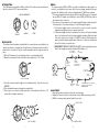
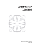
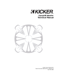
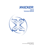
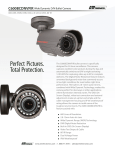
Specifications:
Typical @ 25° C ±5° C
Image
Image Sensor
Resolution
Minimum Illumination
Signal to Noise Ratio
AGC
Lens
Power
Power supply part #
Power consumption
NTSC (Color)
1/3” Sony Superhad™ CCD
380 TV lines
0.5 lux
45 dB
Yes
3.6mm F2.0
12 VDC
219704
1.5 W
Model 7400 B&W
HIGH PERFORMANCE
VIDEO CAMERA
Warranty
Linear LLC warrants this product to be free from defects in material and workmanship for 5 years. The
time period will be measured using the date code labeled on the product. Linear LLC is not responsible
for damage to the product resulting from the buyer’s improper handling, stocking or warehousing of
the product. Any implied warranty arising from the sale of the product including implied warranties of
merchantability and fitness for purpose are limited. Linear LLC shall not be responsible for any losses,
damages or expenses, whether direct, consequential, or incidental arising from the use or the inability to
use the product. Some states and countries do not allow limitations or how long an implied warranty lasts
or the exclusion or limitation or incidental or consequential damages, so the above exclusions may not
apply. The Linear LLC warranty gives specific legal rights in addition to other rights, which may exist and
vary from state to state and country to country.
The warranty is limited to repair or replacement of products returned, freight prepaid, to Linear LLC, there
is NO PROVISION FOR LABOR COST OR OTHER REIMBURSEMENTS OF ANY KIND.
1. Failures due to product abuse, such as negligence, improper use, and electrical surge including
damage from lightning, water damage or other damage due to natural disasters are not covered by
the warranty. The most common form of product abuse is surge damage caused by lightning.
2. The warranty shall also be voided by any tampering with the date code, labels or other markings on
the product.
3. Products that are damaged in transit to Linear LLC due to improper packaging or by the carrier
(shipping company) will not be covered under the warranty. If the product was damaged or lost by the
carrier, it is the sender’s responsibility to create a claim against the carrier.
4. The user is responsible for all labor costs associated with removing, reinstalling and returning the
product to Linear LLC.
Linear LLC, at its option, will repair or replace the defective product. Replacements will be made from BStock, if an exact replacement is not available, Linear LLC, at its option, will select the nearest equivalent
product. The user is responsible for freight charges to Linear LLC. Linear LLC will return warranted repaired
or replacements by UPS Ground or an equivalent service. A customer may pay the additional costs for
second-day or next-day service.
All products returned for warranty service require a Return Product Authorization Number (RPA#). Contact
Linear Technical Services at 1-800-999-5225 for an RPA# and other important details.
Copyright © 2004 Linear LLC
9900582 X1
FEATURES
• Low-Profile/Small Size
Easy to Conceal
• Surface-Mount
Ideal for many different applications
• Easy Installation
Save valuable time!
INTRODUCTION
The 7400 camera is available in White or Black. The surface-mount unit allows for
discrete, attractive CCTV camera installation.
CAMERA COMPONENTS
MAIN
BRACKET
CAMERA
DOME
INSTALLATION
The surface-mount hardware included with the camera allows easy installation in
almost any situation, including retro-fit applications. Provisions must be made for
physical wire connections, but the camera assembly itself is simply screwed in
place.
1. Drill a 3/4” diameter hole in mounting surface to accommodate wiring.
2. Mount the main bracket in the desired location using three 1-1/4” screws.
WIRING
The camera requires RG6 or RG59 coax cable to distribute the video signal to a
monitor’s or modulator’s video input. Use the power supply provided for proper
operation. No additional cable or wire is shipped with the 7400 Series cameras.
1. The camera supplies video through the yellow female RCA connector. If required,
use an RCA-to-F adapter (not included) to connect RG6 or RG59 video cable to
the camera’s video connector.
2. The camera receives power from the power supply through a female mini-jack.
Connect power to the camera using one of the following two options:
a. If the power supply can be located near the camera, connect the power
supply’s mini-plug directly to the camera’s mini-jack.
b. If the power supply cannot be located near the camera, cut the power supply
wire a few inches back from the power supply’s mini-plug. Strip both ends
of the wire and connect a length of 18 AWG 2-conductor wire between the
mini-jack and the power supply’s wire. Solder the connections and insulate
with electrical tape or use wire nuts.
✶ IMPORTANT! OBSERVE PROPER POLARITY when extending the power
wire. Power supply wire polarity marking: White Stripe = (+)
YELLOW FEMALE
RCA CONNECTOR
MALE
F-CONNECTOR
MALE RCA
TO FEMALE
TYPE-F ADAPTOR
(NOT INCLUDED)
VIDEO OUT
FROM
CAMERA
TO VIDEO MONITOR OR
CHANNEL PLUS MODULATOR INPUT
12 VDC 300mA
POWER SUPPLY
7400 SERIES
VIDEO CAMERA
USE 1-1/4" SCREWS
3. Feed the camera leads through hole in mounting surface. Connect wires (see
WIRING).
4. Place assembled camera housing into main bracket.
5. Place dome over camera housing and attach to main bracket with three 1/2”
screws. Do not tighten completely.
WHITE
STRIPE = (+)
12 VDC
POWER
TO CAMERA
BLACK FEMALE
MINI-JACK
MALE
MINI-PLUG
TO EXTEND POWER SUPPLY CONNECTION,
USE 18 AWG 2-CONDUCTOR WIRE
OBSERVE POLARITY
ADJUSTMENT
1. After wiring, make provisions to view the camera image.
2. Adjust the camera to point it at the desired location. Make sure image is level!
3. With the camera properly aimed, tighten the screws.
1. ADJUST VIEW
USE 1/2" SCREWS
1
2. TIGHTEN SCREWS
2