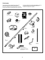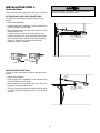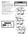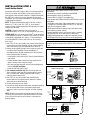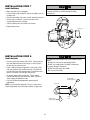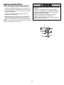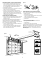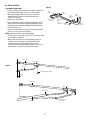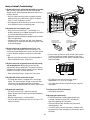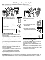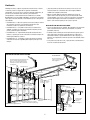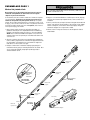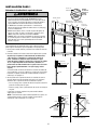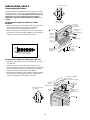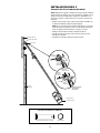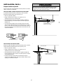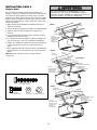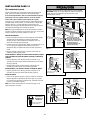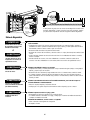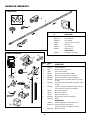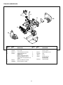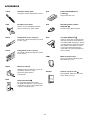
1
®
The Chamberlain Group, Inc.
845 Larch Avenue
Elmhurst, Illinois 60126-1196
www.chamberlain.com
®
GARAGE DOOR OPENER
Model HD900D
For Residential Use Only
Owner’s Manual
■
Please read this manual and the enclosed safety materials carefully!
■
Fasten the manual near the garage door after installation.
■
The door WILL NOT CLOSE unless The Protector System® is connected and properly aligned.
■
Periodic checks of the opener are required to ensure safe operation.
■
The model number label is located on the left side panel of your opener.
TABLE OF CONTENTS
Introduction
2-7
Adjustment
Safety symbol and signal word review . . . . . . . . . . . . . . . . . . . . 2
Preparing your garage door . . . . . . . . . . . . . . . . . . . . . . . . . . . . 3
Tools needed . . . . . . . . . . . . . . . . . . . . . . . . . . . . . . . . . . . . . . . 3
Planning . . . . . . . . . . . . . . . . . . . . . . . . . . . . . . . . . . . . . . . . . 4-5
Carton inventory . . . . . . . . . . . . . . . . . . . . . . . . . . . . . . . . . . . . . 6
Hardware inventory. . . . . . . . . . . . . . . . . . . . . . . . . . . . . . . . . . . 7
Assembly
Operation
Assemble the rail and install the trolley . . . . . . . . . . . . . . . . . . . 8
Fasten the rail to the motor unit . . . . . . . . . . . . . . . . . . . . . . . . . 9
Install the idler pulley . . . . . . . . . . . . . . . . . . . . . . . . . . . . . . . . . 9
Install the belt and attach the belt cap retainer . . . . . . . . . . . . . 10
Set the tension . . . . . . . . . . . . . . . . . . . . . . . . . . . . . . . . . . . . . 11
11-27
Installation safety instructions . . . . . . . . . . . . . . . . . . . . . . . . . 11
Determine the header bracket location . . . . . . . . . . . . . . . . . . . 12
Install the header bracket . . . . . . . . . . . . . . . . . . . . . . . . . . . . . 13
Attach the rail to the header bracket . . . . . . . . . . . . . . . . . . . . . 14
Position the opener. . . . . . . . . . . . . . . . . . . . . . . . . . . . . . . . . . 15
Hang the opener . . . . . . . . . . . . . . . . . . . . . . . . . . . . . . . . . . . . 16
Install the door control . . . . . . . . . . . . . . . . . . . . . . . . . . . . . . . 17
Install the battery . . . . . . . . . . . . . . . . . . . . . . . . . . . . . . . . . . . 18
Install the lights . . . . . . . . . . . . . . . . . . . . . . . . . . . . . . . . . . . . 18
Attach the emergency release rope and handle . . . . . . . . . . . . 19
Electrical requirements . . . . . . . . . . . . . . . . . . . . . . . . . . . . . . . 20
Install The Protector System® . . . . . . . . . . . . . . . . . . . . . . 21-23
Fasten the door bracket . . . . . . . . . . . . . . . . . . . . . . . . . . . 24-25
Connect the door arm to the trolley . . . . . . . . . . . . . . . . . . 26-27
Programming
31
31
32
33
34
34
35
36
37
38-39
To add or reprogram a hand-held remote control . . . . . . . . . .
To erase all codes from motor unit memory . . . . . . . . . . . . . .
3-Button remotes . . . . . . . . . . . . . . . . . . . . . . . . . . . . . . . . . . .
To add, reprogram or change a Keyless Entry PIN. . . . . . . . . .
Repair Parts
28
29
30
30
31-37
Operation safety instructions . . . . . . . . . . . . . . . . . . . . . . . . . .
Using your garage door opener . . . . . . . . . . . . . . . . . . . . . . . .
Using the wall-mounted door control . . . . . . . . . . . . . . . . . . . .
Battery Backup (Optional). . . . . . . . . . . . . . . . . . . . . . . . . . . . .
To open the door manually. . . . . . . . . . . . . . . . . . . . . . . . . . . .
Care of your opener . . . . . . . . . . . . . . . . . . . . . . . . . . . . . . . . .
Having a problem? (Troubleshooting) . . . . . . . . . . . . . . . . . . .
Diagnostic chart . . . . . . . . . . . . . . . . . . . . . . . . . . . . . . . . . . . .
Smart Control Panel® messages. . . . . . . . . . . . . . . . . . . . . . . .
8-11
Installation
28-30
Program the travel limits . . . . . . . . . . . . . . . . . . . . . . . . . . . . .
Set the force . . . . . . . . . . . . . . . . . . . . . . . . . . . . . . . . . . . . . . .
Test the safety reversal system. . . . . . . . . . . . . . . . . . . . . . . . .
Test The Protector System® . . . . . . . . . . . . . . . . . . . . . . . . . . .
38
38
38
39
40-41
Rail assembly parts . . . . . . . . . . . . . . . . . . . . . . . . . . . . . . . . . 40
Installation parts . . . . . . . . . . . . . . . . . . . . . . . . . . . . . . . . . . . . 40
Motor unit assembly parts . . . . . . . . . . . . . . . . . . . . . . . . . . . . 41
Notas
42
Accessories
43
Repair Parts and Service
44
Warranty
44
INTRODUCTION
Safety Symbol and Signal Word Review
This garage door opener has been designed and tested to offer safe service provided it is installed, operated, maintained and tested in
strict accordance with the instructions and warnings contained in this manual.
When you see these Safety Symbols and Signal Words on the
following pages, they will alert you to the possibility of serious
injury or death if you do not comply with the warnings that
accompany them. The hazard may come from something
mechanical or from electric shock. Read the warnings carefully.
Mechanical
When you see this Signal Word on the following pages, it will
alert you to the possibility of damage to your garage door and/or
the garage door opener if you do not comply with the cautionary
statements that accompany it. Read them carefully.
Electrical
2
Preparing your garage door
Before you begin:
• Disable locks.
• Remove any ropes connected to garage door.
• Complete the following test to make sure your garage door is
balanced and is not sticking or binding:
1. Lift the door about halfway as shown. Release the door. If
balanced, it should stay in place, supported entirely by its
springs.
2. Raise and lower the door to see if there is any binding or
sticking.
If your door binds, sticks, or is out of balance, call a trained door
systems technician.
To prevent possible SERIOUS INJURY or DEATH:
• ALWAYS call a trained door systems technician if garage
door binds, sticks, or is out of balance. An unbalanced
garage door may not reverse when required.
• NEVER try to loosen, move or adjust garage door, door
springs, cables, pulleys, brackets or their hardware, ALL of
which are under EXTREME tension.
• Disable ALL locks and remove ALL ropes connected to
garage door BEFORE installing and operating garage door
opener to avoid entanglement.
To prevent damage to garage door and opener:
• ALWAYS disable locks BEFORE installing and operating the
opener.
• ONLY operate garage door opener at 120V, 60 Hz to avoid
malfunction and damage.
1 2
Sectional Door
One-Piece Door
Tools needed
During assembly, installation and adjustment of the opener,
instructions will call for hand tools as illustrated below.
Carpenter’s
Level (optional)
1
2
Pencil
Hack Saw
Tape Measure
Claw Hammer
Drill
Stepladder
Drill Bits
3/16", 5/16"
and 5/32"
Wire Cutters
Screwdriver
Pliers
Sockets and Wrench
1/2", 5/8", 7/16", 9/16"
and 1/4"
Adjustable End Wrench
3
Planning
• Do you have an access door in addition to the garage door? If
not, Model 7702CB Emergency Key Release is required. See
Accessories page.
• Look at the garage door where it meets the floor. Any gap
between the floor and the bottom of the door must not exceed
1/4" (6 mm). Otherwise, the safety reversal system may not
work properly. See Adjustment Step 3. Floor or door should be
repaired.
Identify the type and height of your garage door. Survey your
garage area to see if any of the conditions below apply to your
installation. Additional materials may be required. You may find it
helpful to refer back to this page and the accompanying
illustrations as you proceed with the installation of your opener.
Depending on your requirements, there are several installation
steps which may call for materials or hardware not included in
the carton.
• Installation Step 1 – Look at the wall or ceiling above the
garage door. The header bracket must be securely fastened to
structural supports.
• Installation Step 5 – Do you have a finished ceiling in your
garage? If so, a support bracket and additional fastening
hardware may be required.
• Installation Step 11 – Depending upon garage construction,
extension brackets or wood blocks may be needed to install
sensors.
• Installation Step 11 – Alternate floor mounting of the safety
reversing sensor will require hardware not provided.
SECTIONAL DOOR INSTALLATIONS
• Do you have a steel, aluminum, fiberglass or glass panel door?
If so, horizontal and vertical reinforcement is required
(Installation Step 12).
• The opener should be installed above the center of the door. If
there is a torsion spring or center bearing plate in the way of
the header bracket, it may be installed within 4 feet (1.2 m) to
the left or right of the door center. See Installation Steps 1
and 12.
• If your door is more than 7 feet (2.1 m) high, see rail extension
kits listed on Accessories page.
SECTIONAL DOOR INSTALLATION
FINISHED CEILING
Support bracket &
fastening hardware
is required.
See page 16.
Horizontal and vertical reinforcement
is needed for lightweight garage doors
(fiberglass, steel, aluminum, door with
glass panels, etc.). See page 24 for details.
Header Wall
Motor unit
Extension Spring
OR
Torsion Spring
Wallmounted
Door
Control
Access Door
———
Vertical
Centerline
of Garage Door
Header
Bracket
———
Trolley
Garage
Door
Spring
——
Safety Reversing Sensor
Gap between floor
and bottom of door
must not exceed 1/4" (6 mm).
CLOSED POSITION
Trolley
Stop Bolt
Belt
Straight
Door
Arm
Safety
Reversing
Sensor
Header
Wall
Garage
Door
4
Door
Bracket
Curved
Door
Arm
Emergency Release
Rope & Handle
Planning (Continued)
ONE-PIECE DOOR INSTALLATIONS
• Generally, a one-piece door does not require reinforcement. If
your door is lightweight, refer to the information relating to
sectional doors in Installation Step 12.
• Depending on your door’s construction, you may need
additional mounting hardware for the door bracket (Step 12).
Without a properly working safety reversal system, persons
(particularly small children) could be SERIOUSLY INJURED or
KILLED by a closing garage door.
• The gap between the bottom of the garage door and the floor
MUST NOT exceed 1/4" (6 mm). Otherwise, the safety
reversal system may not work properly.
• The floor or the garage door MUST be repaired to eliminate
the gap.
ONE-PIECE DOOR WITHOUT TRACK
FINISHED CEILING
Support bracket
& fastening
hardware is required.
See page 16.
Header Wall
Rail
Motor Unit
Wall-mounted
Door Control
Access
Door
CLOSED POSITION
Trolley Stop Bolt
Belt
Header
Bracket
Trolley
Rail
Door Bracket
Safety Reversing Sensor
Safety Reversing
Sensor
Gap between floor
and bottom of door must not exceed 1/4" (6 mm).
Straight
Door
Arm
Header
Wall
Curved
Door
Arm
Emergency
Release
Rope & Handle
Garage
Door
ONE-PIECE DOOR WITH TRACK
CLOSED POSITION
Trolley Stop Bolt
Access
Door
Header
Wall
Header
Bracket
Curved
Door Arm
Door
Bracket
Garage
Door
Safety
Reversing
Sensor
Safety
Reversing
Sensor
Gap between floor
and bottom of door
must not exceed 1/4" (6 mm).
5
Belt
Straight
Door
Arm
Trolley
Rail
Emergency
Release
Rope &
Handle
Carton Inventory
Your garage door opener is packaged in one carton which
contains the motor unit and all parts illustrated below.
Accessories will depend on the model purchased. If anything is
missing, carefully check the packing material. Parts may be stuck
in the foam. Hardware for assembly and installation is shown on
the next page. Save the carton and packing material until
installation and adjustment is complete.
SECURITY✚®
3-Button Remote Control (2)
Idler Pulley
Battery
Smart Contol Panel®
Door Bracket
2-Conductor Bell Wire
White & White/Red
Trolley
SECURITY✚®
Keyless Entry
Rail
Center/Back
Sections
Motor Unit with 2 Light Lenses
Header Bracket
Belt Cap Retainer
Belt
“U” Bracket
Rail
Front (header)
Section
Hanging Brackets
Curved Door
Arm Section
Safety Reversing
Sensor Bracket (2)
The Protector System®
(2) Safety Reversing Sensors
(1 Sending Eye and 1 Receiving Eye)
with 2-Conductor White & White/Black
Bell Wire attached
6
Straight Door
Arm Section
Safety Labels
and
Literature
Hardware Inventory
Separate all hardware and group as shown below for the assembly and installation procedures.
ASSEMBLY HARDWARE
Nut
3/8" (1)
Lock Washer
3/8" (1)
Lock Nut
1/4"-20 (2)
Spring/Trolley Nut (1)
Bolt 1/4"-20x1-3/4" (2)
Master
Link (2)
Idler Bolt (1)
Trolley Threaded Shaft (1)
INSTALLATION HARDWARE
Carriage Bolt
1/4"-20x1/2" (2)
Wing Nut
1/4"-20 (2)
Lag Screw
5/16"-9x1-5/8" (2)
Lag Screw
5/16"-18x1-7/8" (2)
Ring
Fastener (3)
Nut 5/16"-18 (8)
Hex Bolt
5/16"-18x7/8" (4)
Screw
6ABx1-1/4" (2)
Lock Washer 5/16" (7)
Handle
Insulated
Staples (30)
Screw 6-32x1" (2)
Rope
Self-Threading Screw
1/4"-14x5/8" (2)
Clevis Pin
5/16"x1-1/2" (1)
Drywall Anchors (2)
Clevis Pin
5/16"x1" (1)
7
Spacer (2)
Clevis Pin
5/16"x1-1/4" (1)
ASSEMBLY STEP 1
Assemble the Rail & Install the Trolley
To prevent INJURY from pinching, keep hands and fingers
away from the joints while assembling the rail.
To avoid installation difficulties, do not run the garage door
opener until instructed to do so.
The front rail has a cut out “window” at the door end
(see illustration). The hole above this window is larger on the
top of the rail than on the bottom. A smaller hole 3-1/2"
(8.9 cm) away is close to the rail edge. Rotate the back rail so it
has a similar hole close to the opposite edge, about 4-3/4"
(12 cm) from the far end.
1. Remove the straight door arm and hanging bracket packaged
inside the front rail and set aside for Installation Step 5 and 12.
NOTE: To prevent INJURY while unpacking the rail carefully
remove the straight door arm stored within the rail section.
2. Align the rail sections on a flat surface as shown and slide the
tapered ends into the larger ones. Tabs along the side will lock
into place.
3. Place the motor unit on packing material to protect the cover,
and rest the back end of the rail on top. For convenience, put a
support under the front end of the rail.
4. As a temporary stop, insert a screwdriver into the hole
10" (25 cm) from the front end of the rail, as shown.
5. Check to be sure there are 4 plastic wear pads inside the inner
trolley. If they became loose during shipping, check all packing
material. Snap them back into position as shown.
6. Slide the trolley assembly along the rail from the back end to
the screwdriver.
Trolley
Tapered
End
KEEP LARGER
HOLE ON TOP
Tapered
End
FRONT RAIL
(TOP)
Back Rails
(TO MOTOR UNIT)
Tapered
End
Outer Trolley
Tapered
End
Screwdriver
Inner Trolley
Tabs
Window
Cut-Out
Idler
Pulley
Hole
Front Rail
(TO DOOR)
Wear Pads
8
ASSEMBLY STEP 2
Fasten the Rail to the Motor Unit
To avoid SERIOUS damage to garage door opener, use ONLY
those bolts/fasteners mounted in the top of the opener.
• Insert a 1/4"-20x1-3/4" bolt into the cover protection bolt hole
on the back end of the rail as shown. Tighten securely with a
1/4"-20 lock nut. DO NOT overtighten.
• Remove the two bolts from the top of the motor unit.
• Place the “U” bracket, flat side down, on the motor unit and
align the bracket holes with the bolt holes. Fasten with the
previously removed bolts.
• Align the rail assembly with the top of the motor unit. Slide the
rail end onto the “U” bracket, all the way to the stops that
protrude on the top and sides of the bracket.
Motor Unit
Belt Pulley
Bolts
“U” Bracket
Bolt
Cover
Protection
Bolt Hole
HARDWARE SHOWN ACTUAL SIZE
Lock Nut
Bolt 1/4"-20x1-3/4"
SLIDE RAIL TO
STOPS ON TOP
AND SIDES
OF BRACKET
Lock Nut
1/4"-20
Bolt
ASSEMBLY STEP 3
Rail
Install the Idler Pulley
• Lay the belt beside the rail, as shown. Grasp the end with the
hooked trolley connector and pass approximately 12" (30 cm)
of belt through the window. Keep the ribbed side toward the
rail, and allow it to hang until Assembly Step 5.
• Remove the tape from the idler pulley. The inside center should
be pre-greased. If dry, regrease to ensure proper operation.
• Place the idler pulley into the window as shown.
• Insert the idler bolt from the top through the rail and pulley.
Tighten with a 3/8" lock washer and nut underneath the rail
until the lock washer is compressed.
• Rotate the pulley to be sure it spins freely.
• Insert a 1/4"-20x1-3/4" bolt into the trolley stop hole in the
front of the rail as shown. Tighten securely with a 1/4"-20
lock nut.
Pulley
Nut
Idler Bolt
Washer
Screwdriver
Bolt
Trolley
Stop Hole
Grease
Inside Pulley
Idler Pulley
Lock Washer 3/8"
Nut 3/8"
Trolley
Connector
Idler
Pulley
HARDWARE SHOWN ACTUAL SIZE
Idler Bolt
Bolt 1/4"-20x1-3/4"
9
Lock Nut 1/4"-20
Nut 3/8"
Lock Washer 3/8"
Lock
Nut
ASSEMBLY STEP 4
Install the Belt and Attach the Belt Cap Retainer
To avoid possible SERIOUS INJURY to fingers from moving
garage door opener:
• ALWAYS keep hand clear of belt pulley while operating
opener.
• Securely attach belt pulley cover BEFORE operating.
1. Pull the belt around the idler pulley and toward the trolley.
The ribbed side must contact the pulley.
2. Hook the trolley connector into the retaining slot on the trolley
as shown.
3. With the trolley against the screwdriver, dispense the
remainder of the belt along the rail length toward the motor
unit and around the belt pulley. The belt pulley teeth must
engage the belt.
4. Check to make sure the belt is not twisted and the FLAT side
of the trolley threaded shaft is facing the rail. Connect the
trolley threaded shaft with the master link, as illustrated:
• Push pins of master link bar through holes in end of belt
and trolley threaded shaft.
• Push master link cap over pins and past pin notches.
• Slide clip-on spring over cap and onto pin notches until
both pins are securely locked in place.
5. Insert the trolley threaded shaft through the hole in the
trolley. Be sure the belt is not twisted and the FLAT side of
the trolley threaded shaft faces the rail.
6. Hold the belt at the trolley shaft as you thread the spring nut
by hand onto the shaft until finger tight against the trolley.
DO NOT use any tools.
7. Remove the screwdriver.
8. Position the belt cap retainer over the motor unit belt pulley
as shown and fasten to the mounting plate with 8x3/8" hex
screws provided.
HARDWARE SHOWN ACTUAL SIZE
Hex Screw 8x3/8"
Spring/Trolley Nut
Master Link
Clip-On Spring
Master Link Cap
Pin
Notch
Trolley
Threaded
Shaft
Master
Link Bar
Hole
Trolley
Connector
Retaining
Slot
8x3/8" Hex Screws
Belt Cap
Retainer
Idler Pulley
Motor Unit
Belt Pulley
Mounting
Plate
Spring Nut
10
ASSEMBLY STEP 5
Set the Tension
• Insert a screwdriver tip into one of the nut ring slots and brace
it firmly against the trolley.
• Place a 7/16" open end wrench on the square end. Rotate the
nut about 1/4 turn until the spring releases and snaps the nut
ring against the trolley.
This sets the spring to optimum belt tension.
Nut Ring Slot
Square End
You have now finished assembling your garage door opener.
Please read the following warnings before proceeding to the
installation section.
Trolley
Square
End
WARNING
Nut Ring
BEFORE
1"
(2.5 cm)
Nut Ring
AFTER RELEASE
1-1/4"
(3.18 cm)
WARNING
INSTALLATION
IMPORTANT INSTALLATION INSTRUCTIONS
WARNING
To reduce the risk of SEVERE INJURY or DEATH:
1. READ AND FOLLOW ALL INSTALLATION WARNINGS AND
INSTRUCTIONS.
2. Install garage door opener ONLY on properly balanced and
lubricated garage door. An improperly balanced door may
not reverse when required and could result in SEVERE
INJURY or DEATH.
3. ALL repairs to cables, spring assemblies and other
hardware MUST be made by a trained door systems
technician BEFORE installing opener.
4. Disable ALL locks and remove ALL ropes connected to
garage door BEFORE installing opener to avoid
entanglement.
5. Install garage door opener 7 feet (2.1 m) or more above
floor.
6. Mount emergency release handle 6 feet (1.8 m) above floor.
7. NEVER connect garage door opener to power source until
instructed to do so.
8. NEVER wear watches, rings or loose clothing while
installing or servicing opener. They could be caught in
garage door or opener mechanisms.
9. Install wall-mounted garage door control:
• within sight of the garage door.
• out of reach of children at minimum height of 5 feet
(1.5 m).
• away from ALL moving parts of the door.
10. Place entrapment warning label on wall next to garage
door control.
11. Place manual release/safety reverse test label in plain view
on inside of garage door.
12. Upon completion of installation, test safety reversal
system. Door MUST reverse on contact with a 1-1/2"
(3.8 cm) high object (or a 2x4 laid flat) on the floor.
13. To avoid SERIOUS PERSONAL INJURY or DEATH from
electrocution, disconnect ALL electric and battery power
BEFORE performing ANY service or maintenance.
11
INSTALLATION STEP 1
Unfinished
Ceiling
Determine the Header Bracket Location
To prevent possible SERIOUS INJURY or DEATH:
• Header bracket MUST be RIGIDLY fastened to structural
support on header wall or ceiling, otherwise garage door
might not reverse when required. DO NOT install header
bracket over drywall.
• Concrete anchors MUST be used if mounting header bracket
or 2x4 into masonry.
• NEVER try to loosen, move or adjust garage door, springs,
cables, pulleys, brackets, or their hardware, ALL of which
are under EXTREME tension.
• ALWAYS call a trained door systems technician if garage
door binds, sticks, or is out of balance. An unbalanced
garage door might not reverse when required.
OPTIONAL
CEILING
MOUNT
FOR
HEADER
BRACKET
2x4
Header Wall
Vertical Centerline
of Garage Door
2x4
Structural
Supports
Level
(optional)
Installation procedures vary according to garage door types.
Follow the instructions which apply to your door.
1. Close the door and mark the inside vertical centerline of the
garage door.
2. Extend the line onto the header wall above the door.
You can fasten the header bracket within 4' (1.22 m) of the
left or right of the door center only if a torsion spring or
center bearing plate is in the way; or you can attach it to the
ceiling (see page 13) when clearance is minimal. (It may be
mounted on the wall upside down if necessary, to gain
approximately 1/2" (1 cm).)
If you need to install the header bracket on a 2x4 (on wall or
ceiling), use lag screws (not provided) to securely fasten the
2x4 to structural supports as shown here and on page 13.
3. Open your door to the highest point of travel as shown. Draw
an intersecting horizontal line on the header wall above the
high point:
• 2" (5 cm) above the high point for sectional door and
one-piece door with track.
• 8" (20 cm) above the high point for one-piece door without
track.
This height will provide travel clearance for the top edge of the
door.
NOTE: If the total number of inches exceeds the height
available in your garage, use the maximum height possible, or
refer to page 13 for ceiling installation.
Header Wall
2" (5 cm)
Track
Header Wall
2" (5 cm)
Track
Highest Point
of Travel
Highest Point
of Travel
Door
Door
Sectional door with curved track
One-piece door with horizontal track
Header Wall
Header Wall
8" (20 cm)
8" (20 cm)
Door
Highest
Point
of Travel
Highest
Point
of Travel
Door
Jamb
Hardware
Pivot
One-piece door without track:
jamb hardware
12
One-piece door without track:
pivot hardware
INSTALLATION STEP 2
Wall Mount
Install the Header Bracket
You can attach the header bracket either to the wall above the
garage door, or to the ceiling. Follow the instructions which will
work best for your particular requirements. Do not install the
header bracket over drywall. If installing into masonry, use
concrete anchors (not provided).
UP
WALL HEADER BRACKET INSTALLATION
• Center the bracket on the vertical centerline with the bottom
edge of the bracket on the horizontal line as shown
(with the arrow pointing toward the ceiling).
• Mark the vertical set of bracket holes. Drill 3/16" pilot holes and
fasten the bracket securely to a structural support with the
hardware provided.
Optional
Mounting Holes
Vertical
Centerline
of Garage Door
Header Wall
2x4
Structural
Support
Header
Bracket
Lag Screws
5/16"x9x1-5/8"
Door Spring
HARDWARE SHOWN ACTUAL SIZE
Horizontal
Line
Garage Door
Highest Point of
Garage Door Travel
Lag Screw
5/16"x9x1-5/8"
Vertical
Centerline
of Garage Door
CEILING HEADER BRACKET INSTALLATION
• Extend the vertical centerline onto the ceiling as shown.
• Center the bracket on the vertical mark, no more than
6" (15 cm) from the wall. Make sure the arrow is pointing away
from the wall. The bracket can be mounted flush against the
ceiling when clearance is minimal.
• Mark the side holes. Drill 3/16" pilot holes and fasten bracket
securely to a structural support with the hardware provided.
– Finished Ceiling –
Vertical Centerline
of Garage Door
Header
Bracket
6" (15 cm) Maximum
Door
Spring
Ceiling Mounting Holes
Lag Screws
5/16"x9x1-5/8"
UP
Header Wall
Garage Door
13
Vertical
Centerline
of Garage Door
INSTALLATION STEP 3
Attach the Rail to the Header Bracket
NOTE: (Optional) With some existing installations, you may
re-use the old header bracket with the two plastic spacers
included in the hardware bag. Place the spacers inside the bracket
on each side of the rail, as illustrated.
• Position the opener on the garage floor below the header
bracket. Use packing material as a protective base.
NOTE: If the door spring is in the way you’ll need help. Have
someone hold the opener securely on a temporary support to
allow the rail to clear the spring.
• Position the rail bracket against the header bracket.
• Align the bracket holes and join with a clevis pin as shown.
• Insert a ring fastener to secure.
Header Wall
Header Bracket
Idler Pulley
Header
Bracket
Mounting
Hole
Existing
Header Bracket
Existing
Clevis Pin
Spacer
Mounting
Hole
Garage
Door
OPTION WITH
SOME EXISTING
INSTALLATIONS
Opener Carton or
Temporary
Support
HARDWARE SHOWN ACTUAL SIZE
Clevis Pin 5/16"x1-1/2"
Ring Fastener
14
INSTALLATION STEP 4
Position the Opener
To prevent damage to garage door, rest garage door opener
rail on 2x4 placed on top section of door.
Follow instructions which apply to your door type as illustrated.
SECTIONAL DOOR OR ONE-PIECE DOOR WITH TRACK
A 2x4 laid flat is convenient for setting an ideal door-to-rail
distance.
• Remove foam packaging.
• Raise the opener onto a stepladder. You will need help at this
point if the ladder is not tall enough.
• Open the door all the way and place a 2x4 laid flat on the top
section beneath the rail.
• If the top section or panel hits the trolley when you raise
the door, pull down on the trolley release arm to disconnect
inner and outer sections. Slide the outer trolley toward the
motor unit. The trolley can remain disconnected until
Installation Step 12 is completed.
ENGAGED
Rail
Door
2x4 is used to determine
the correct mounting height
from ceiling.
Trolley
Release Arm
RELEASED
ONE-PIECE DOOR WITHOUT TRACK
A 2x4 on its side is convenient for setting an ideal door-to-rail
distance.
• Remove foam packaging.
• Raise the opener onto a stepladder. You will need help at this
point if the ladder is not tall enough.
• Open the door all the way and place a 2x4 on its side on the
top section of the door beneath the rail.
• The top of the door should be level with the top of the motor
unit. Do not position the opener more than 4" (10 cm) above
this point.
Header
Bracket
Top of Door
2x4 is used to determine
the correct mounting height
from ceiling.
15
INSTALLATION STEP 5
Hang the Opener
To avoid possible SERIOUS INJURY from a falling garage door
opener, fasten it SECURELY to structural supports of the
garage. Concrete anchors MUST be used if installing ANY
brackets into masonry.
Three representative installations are shown. Yours may be
different. Hanging brackets should be angled (Figure 1) to provide
rigid support. On finished ceilings (Figures 2 and Figure 3), attach
a sturdy metal bracket to structural supports before installing the
opener. This bracket and fastening hardware are not provided.
1. Measure the distance from each side of the motor unit to the
structural support.
2. Cut both pieces of the hanging bracket to required lengths.
3. Drill 3/16" pilot holes in the structural supports.
4. Attach one end of each bracket to a support with
5/16"-18x1-7/8" lag screws.
5. Fasten the opener to the hanging brackets with
5/16"-18x7/8" hex bolts, lock washers and nuts.
6. Check to make sure the rail is centered over the door (or in line
with the header bracket if the bracket is not centered above the
door).
7. Remove the 2x4. Operate the door manually. If the door hits
the rail, raise the header bracket.
NOTE: DO NOT connect power to opener at this time.
Figure 1
Structural
Supports
Lag Screws
5/16"-18x1-7/8"
Measure
Distance
Bolt 5/16"-18x7/8"
Lock Washer 5/16"
Nut 5/16"-18
Figure 2
Bracket
(Not Provided)
Hidden
Support
FINISHED CEILING
Lag Screws
5/16"-18x1-7/8"
(Not Provided)
Bolt 5/16"-18x7/8"
Lock Washer 5/16"
Nut 5/16"-18
Bolt 5/16"-18x7/8"
Lock Washer 5/16"
Nut 5/16"-18
HARDWARE SHOWN ACTUAL SIZE
Lag Screw 5/16"-18x1-7/8"
Figure 3
Lag Screws
5/16"-18x1-7/8"
Hex Bolt
5/16"-18x7/8"
Nut 5/16"-18
FINISHED CEILING
Lock Washer 5/16"
(Not Provided)
Bolt 5/16"-18x7/8"
Lock Washer 5/16"
Nut 5/16"-18
Bolt 5/16"-18x7/8"
Lock Washer 5/16"
Nut 5/16"-18
16
INSTALLATION STEP 6
Install the Door Control
To prevent possible SERIOUS INJURY or DEATH from
electrocution:
• Disconnect ALL electric and battery power BEFORE
performing ANY service or maintenance.
• Connect ONLY to 24 VOLT low voltage wires.
To prevent possible SERIOUS INJURY or DEATH from a closing
garage door:
• Install door control within sight of garage door, out of reach
of children at a minimum height of 5 feet (1.5 m), and away
from ALL moving parts of door.
• NEVER permit children to operate or play with door control
push buttons or remote controls.
• Activate door ONLY when it can be seen clearly, is properly
adjusted and there are no obstructions to door travel.
• ALWAYS keep garage door in sight until completely closed.
NEVER permit anyone to cross path of closing garage door.
Locate door control within sight of door, at a minimum height of
5 feet (1.5 m) where small children cannot reach, away from
moving parts of door and door hardware. If installing into drywall,
drill 5/32" holes and use the anchors provided. For pre-wired
installations (as in new home construction), it may be mounted to
a single gang box (Figure 2).
NOTE: The functional temperature range of the door control is
between -4° F (-20° C) and 122° F (50° C). Scroll speed of
display is slower at lower temperatures although the door control
remains fully functional.
CAUTION: Continuous exposure of the door control to
temperatures below -22° F (-30° C) may damage the LCD screen.
SPECIAL NOTE: Only one Smart Control Panel® can be connected
to each garage door opener. If additional wall controls are desired
to operate the same garage door opener, it is recommended to
use model 41A6345-1 wireless wall control as the secondary
door control.
1. Strip 7/16" (11 mm) of insulation from one end of bell wire and
connect to the two screw terminals on back of door control by
color: white wire to W (2) and white/red wire to the R (1).
2. Remove cover by gently prying at slot in top of the cover with
a small flat head screwdriver. Fasten with 6ABx1-1/4"
self-tapping screws (drywall installation) or 6-32x1" machine
screws (into gang box) as follows:
• Install bottom screw, allowing 1/8" (3 mm) to protrude above
wall surface.
• Position bottom of door control on screw head and slide
down to secure. Adjust screw for snug fit.
• Drill and install top screw with care to avoid cracking plastic
housing. DO NOT overtighten.
• Insert top tabs and snap on cover.
3. (For standard installation only) Run bell wire up wall and
across ceiling to motor unit. Use insulated staples to secure
wire in several places. DO NOT pierce wire with a staple,
creating a short or open circuit.
4. Strip 7/16" (11 mm) of insulation from end of bell wire.
Connect bell wire to the quick-connect terminals as follows:
white to white and white/red to red.
5. Position the antenna wire as shown.
6. Use tacks or staples to permanently attach entrapment warning
label to wall near door control, and manual release/safety
reverse test label in a prominent location on inside of garage
door.
NOTE: DO NOT connect power and operate opener at this time.
The trolley will travel to the full open position but will not return
to the close position until the sensor beam is connected and
properly aligned.
Outside Keylock Accessory Connections
To opener quick-connect terminals: white to white; white/red
to red.
HARDWARE SHOWN ACTUAL SIZE
Insulated
Staples
Screw 6ABx1-1/4"
(std installation)
Screw 6-32x1"
(pre-wired)
Drywall Anchors
Figure 1
Figure 2
PRE-WIRED INSTALLATION
REMOVE & REPLACE COVER
To Replace
Insert Top
Tabs First
Push Bar Cover
24 Volt Bell Wire
Top
Mounting
Hole
Bell
Wire
Terminal
Screws
R
1
W
2
Bottom
Mounting
Hole
(BACK VIEW)
Door Control Connections
To insert or release wire, push
in tab with screwdriver tip
Strip wire 7/16" (11 mm)
7/16" (11 mm)
Red White Grey
17
INSTALLATION STEP 7
Install the Battery
ALWAYS wear protective gloves and eye protection when
changing the battery or working around the battery
compartment.
• Make sure motor unit is unplugged.
• Using a Phillips head screwdriver, remove the battery cover on
the motor unit.
• Partially insert battery into motor unit with terminals facing out.
• Connect red (+) and black (-) wires from motor unit to
corresponding terminals on battery.
• Verify the battery wires are seated in the channel.
• Replace battery cover.
Channel
Battery
Battery Cover
INSTALLATION STEP 8
Install the Lights
To prevent possible OVERHEATING of the endpanel or light
socket:
• DO NOT use short neck or specialty light bulbs.
• DO NOT use halogen bulbs. Use ONLY incandescent.
To prevent damage to the opener:
• DO NOT use bulbs larger than 100W.
• ONLY use A19 size bulbs.
• Press the release tabs on both sides of lens. Gently rotate lens
back and downward until the lens hinge is in the fully open
position. Do not remove the lens.
• Install a 100 watt maximum light bulb in each socket. Light
bulb size should be A19, standard neck only. The lights will
turn ON and remain lit for approximately 4-1/2 minutes when
power is connected. Then the lights will turn OFF.
• To remove, depress both top lens tabs. Tilt lens slightly
outward and down, then pull out to clear bulbs. Use care to
avoid snapping off bottom lens tabs.
• Use A19, standard neck garage door opener bulbs for
replacement.
NOTE: Use only standard light bulbs. The use of short neck or
speciality light bulbs may overheat the endpanel or light socket.
100 Watt (Max)
Standard Light Bulb
Release Tab
100 Watt (Max)
Standard Light Bulb
18
Lens
Hinge
INSTALLATION STEP 9
Attach the Emergency Release Rope and Handle
To prevent possible SERIOUS INJURY or DEATH from a falling
garage door:
• If possible, use emergency release handle to disengage
trolley ONLY when garage door is CLOSED. Weak or broken
springs or unbalanced door could result in an open door
falling rapidly and/or unexpectedly.
• NEVER use emergency release handle unless garage
doorway is clear of persons and obstructions.
• NEVER use handle to pull door open or closed. If rope knot
becomes untied, you could fall.
• Thread one end of the rope through the hole in the top of the
red handle so “NOTICE” reads right side up as shown. Secure
with an overhand knot at least 1" (2.5 cm) from the end of the
rope to prevent slipping.
• Thread the other end of the rope through the hole in the
release arm of the outer trolley.
• Adjust rope length so the handle is 6 feet (1.8 m) above the
floor. Ensure that the rope and handle clear the tops of all
vehicles to avoid entanglement. Secure with an overhand knot.
NOTE: If it is necessary to cut the rope, heat seal the cut end with
a match or lighter to prevent unraveling.
Trolley
Trolley
Release Arm
Emergency
Release Handle
19
NOT
ICE
Overhand
Knot
INSTALLATION STEP 10
Electrical Requirements
To prevent possible SERIOUS INJURY or DEATH from
electrocution or fire:
• Disconnect ALL electric and battery power BEFORE
performing ANY service or maintenance.
• Garage door installation and wiring MUST be in compliance
with ALL local electrical and building codes.
• NEVER use an extension cord, 2-wire adapter, or change
plug in ANY way to make it fit outlet. Be sure the opener is
grounded.
To avoid installation difficulties, do not run the opener at this
time.
To reduce the risk of electric shock, your garage door opener has
a grounding type plug with a third grounding pin. This plug will
only fit into a grounding type outlet. If the plug doesn’t fit into the
outlet you have, contact a qualified electrician to install the proper
outlet.
PERMANENT WIRING
CONNECTION
RIGHT
WRONG
Ground Tab
If permanent wiring is required by your local code, refer to the
following procedure.
To make a permanent connection through the 7/8" hole in the top
of the motor unit:
• Remove the motor unit cover screws and set the cover aside.
• Remove the attached 3-prong cord.
• Connect the black (line) wire to the screw on the brass
terminal; the white (neutral) wire to the screw on the silver
terminal; and the ground wire to the green ground screw.
The opener must be grounded.
• Reinstall the cover.
To avoid installation difficulties, do not run the opener at
this time.
Green
Ground Screw
Black
Wire
Ground Wire
White Wire
20
Black Wire
INSTALLATION STEP 11
Install The Protector System®
Be sure power is not connected to the garage door opener
BEFORE installing the safety reversing sensor.
To prevent SERIOUS INJURY or DEATH from a closing garage
door:
• Correctly connect and align the safety reversing sensor. This
required safety device MUST NOT be disabled.
• Install the safety reversing sensor so beam is NO HIGHER
than 6" (15 cm) above garage floor.
The safety reversing sensor must be connected and aligned
correctly before the garage door opener will move in the down
direction.
IMPORTANT INFORMATION ABOUT
THE SAFETY REVERSING SENSOR
When properly connected and aligned, the sensor will detect an
obstacle in the path of its electronic beam. The sending eye (with
an amber indicator light) transmits an invisible light beam to the
receiving eye (with a green indicator light). If an obstruction
breaks the light beam while the door is closing, the door will stop
and reverse to full open position, and the opener lights will flash
10 times.
The units must be installed inside the garage so that the sending
and receiving eyes face each other across the door, no more than
6" (15 cm) above the floor. Either can be installed on the left or
right of the door as long as the sun never shines directly into the
receiving eye lens.
The mounting brackets are designed to clip onto the track of
sectional garage doors without additional hardware.
Safety Reversing Sensor
6" (15 cm) max.
above floor
If it is necessary to mount the units on the wall, the brackets
must be securely fastened to a solid surface such as the wall
framing. Extension brackets (see Accessories) are available if
needed. If installing in masonry construction, add a piece of wood
at each location to avoid drilling extra holes in masonry if
repositioning is necessary.
The invisible light beam path must be unobstructed. No part of
the garage door (or door tracks, springs, hinges, rollers or other
hardware) may interrupt the beam while the door is closing.
Safety Reversing Sensor
6" (15 cm) max.
above floor
Invisible Light Beam
Protection Area
Facing the door from inside the garage.
21
INSTALLING THE BRACKETS
Be sure power to the opener is disconnected. Install and align
the brackets so the sensors will face each other across the garage
door, with the beam no higher than 6" (15 cm) above the floor.
They may be installed in one of three ways, as follows.
Figure 1
DOOR TRACK MOUNT (RIGHT SIDE)
Door
Track
Garage door track installation (preferred):
• Slip the curved arms over the rounded edge of each door track,
with the curved arms facing the door. Snap into place against
the side of the track. It should lie flush, with the lip hugging the
back edge of the track, as shown in Figure 1.
If your door track will not support the bracket securely, wall
installation is recommended.
Lip
Indicator
Light
Sensor
Bracket
Wall installation (Figures 2 & 3):
• Place the bracket against the wall with curved arms facing the
door. Be sure there is enough clearance for the sensor beam to
be unobstructed.
• If additional depth is needed, an extension bracket
(see Accessories) or wood blocks can be used.
• Use bracket mounting holes as a template to locate and drill
(2) 3/16" diameter pilot holes on the wall at each side of the
door, no higher than 6" (15 cm) above the floor.
• Attach brackets to wall with lag screws (not provided).
• If using extension brackets or wood blocks, adjust right and
left assemblies to the same distance out from the mounting
surface. Make sure all door hardware obstructions are cleared.
Figure 2
Lens
WALL MOUNT (RIGHT SIDE)
de
Insi ge
a
Gar
ll
Wa
Fasten Wood Block to Wall with
Lag Screws (not provided)
Indicator
Light
Lag Screws
(not provided)
Lens
Floor installation (Figure 4):
• Use wood blocks or extension brackets (see Accessories) to
elevate sensor brackets so the lenses will be no higher than 6"
(15 cm) above the floor.
• Carefully measure and place right and left assemblies at the
same distance out from the wall. Be sure all door hardware
obstructions are cleared.
• Fasten to the floor with concrete anchors as shown.
Figure 3
WALL MOUNT (RIGHT SIDE)
de
Insi ge
a
Gar
ll
Wa
Extension Bracket
(See Accessories)
(Provided with
Extension Bracket)
(Provided with
Extension Bracket)
Lens
Figure 4
Sensor
Bracket
Indicator
Light
FLOOR MOUNT (RIGHT SIDE)
HARDWARE SHOWN ACTUAL SIZE
Attach with
Concrete Anchors
(not provided)
ide
Ins age
r
a
G l
l
Wa
Lens
Carriage Bolt
1/4"-20x1/2"
Wing Nut
1/4"-20
Sensor
Bracket
Indicator
Light
Staples
Sensor
Bracket
22
MOUNTING AND WIRING THE SAFETY REVERSING SENSORS
• Slide a 1/4"-20x1/2" carriage bolt head into the slot on each
sensor. Use wing nuts to fasten sensors to brackets, with
lenses pointing toward each other across the door. Be sure the
lens is not obstructed by a bracket extension (Figure 5).
• Finger tighten the wing nuts.
• Run the wires from both sensors to the opener. Use insulated
staples to secure wire to wall and ceiling.
• Strip 7/16" (11 mm) of insulation from each set of wires.
Separate white and white/black wires sufficiently to connect to
the opener quick-connect terminals. Twist like colored wires
together. Insert wires into quick-connect holes: white to white
and white/black to grey (Figure 6).
Figure 5
Wing Nut
Carriage Bolt
1/4"-20x1/2"
Lens
TROUBLESHOOTING THE SAFETY REVERSING SENSORS
1. If the sending eye indicator light does not glow steadily after
installation, check for:
• Electric power to the opener.
• A short in the white or white/black wires. These can occur at
staples, or at opener connections.
• Incorrect wiring between sensors and opener.
• A broken wire.
2. If the sending eye indicator light glows steadily but the
receiving eye indicator light doesn't:
• Check alignment.
• Check for an open wire to the receiving eye.
3. If the receiving eye indicator light is dim, realign either sensor.
NOTE: When the invisible beam path is obstructed or misaligned
while the door is closing, the door will reverse. If the door is
already open, it will not close. The opener lights will blink 10
times. See page 21.
ALIGNING THE SAFETY REVERSING SENSORS
• Plug in the opener. The indicator lights in both the sending and
receiving eyes will glow steadily if wiring connections and
alignment are correct.
The sending eye amber indicator light will glow regardless of
alignment or obstruction. If the green indicator light in the
receiving eye is off, dim, or flickering (and the invisible light beam
path is not obstructed), alignment is required.
• Loosen the sending eye wing nut and readjust, aiming directly
at the receiving eye. Lock in place.
• Loosen the receiving eye wing nut and adjust sensor until it
receives the sender’s beam. When the green indicator light
glows steadily, tighten the wing nut.
Connect Wire to
Quick-Connect Terminals
Figure 6
Bell Wire
Finished
Ceiling
Bell Wire
1. Strip wire 7/16"
(11 mm)
7/16" (11 mm)
2. Twist like colored
wires together
3. To insert or release
wire, push in tab with
screwdriver tip
Safety Reversing
Sensor
Invisible Light Beam
Protection Area
Safety Reversing
Sensor
23
Red White Grey
Quick-Connect Terminals
INSTALLATION STEP 12
Fasten the Door Bracket
Fiberglass, aluminum or lightweight steel garage doors WILL
REQUIRE reinforcement BEFORE installation of door bracket.
Contact your door manufacturer for reinforcement kit.
Follow instructions which apply to your door type as illustrated
below or on the following page.
A horizontal reinforcement brace should be long enough to be
secured to two or three vertical supports. A vertical
reinforcement brace should cover the height of the top panel.
Figure 1 shows one piece of angle iron as the horizontal brace.
For the vertical brace, 2 pieces of angle iron are used to create a
U-shaped support. The best solution is to check with your garage
door manufacturer for an opener installation door reinforcement
kit.
NOTE: Many door reinforcement kits provide for direct
attachment of the clevis pin and door arm. In this case you will
not need the door bracket; proceed to Step 13.
Header
Bracket
Door
Bracket
Location
SECTIONAL DOORS
1. Center the door bracket on the previously marked vertical
centerline used for the header bracket installation. Note correct
UP placement, as stamped inside the bracket.
2. Position the top edge of the bracket 2"-4" (5-10 cm) below the
top edge of the door, OR directly below any structural support
across the top of the door.
3. Mark, drill holes and install as follows, depending on your
door’s construction:
Vertical
Centerline
of Garage
Door
HORIZONTAL AND VERTICAL
REINFORCEMENT IS NEEDED FOR
LIGHTWEIGHT GARAGE DOORS
(FIBERGLASS, ALUMINUM, STEEL,
DOORS WITH GLASS PANEL, ETC.).
(NOT PROVIDED)
Figure 1
Vertical
Reinforcement
Vertical
Centerline
of Garage Door
Vertical
Reinforcement
Metal or light weight doors using a vertical angle iron brace
between the door panel support and the door bracket:
• Drill 3/16" fastening holes. Secure the door bracket using the
two 1/4"-14x5/8" self-threading screws (Figure 2A).
• Alternately, use two 5/16" bolts, lock washers and nuts
(not provided) (Figure 2B).
Vertical
Centerline
of Garage Door
Bolt
5/16"-18x2"
(Not Provided)
UP
Door
Bracket
UP
Metal, insulated or light weight factory reinforced doors:
• Drill 3/16" fastening holes. Secure the door bracket using the
self-threading screws (Figure 3).
Lock Washer
5/16"
Door
Bracket
Self-Threading
Screw 1/4"-14x5/8"
Wood Doors:
• Use top and bottom or side to side door bracket holes. Drill
5/16" holes through the door and secure bracket with 5/16"x2"
carriage bolts, lock washers and nuts (not provided) (Figure 4).
NOTE: The 1/4"-14x5/8" self-threading screws are not intended for
use on wood doors.
Nut
5/16"-18
Figure 2B
Figure 2A
Bolt
5/16"x2"
(Not
Provided)
Inside Edge
of Door or
Reinforcement Board
UP
Vertical
Centerline
of Garage Door
HARDWARE
SHOWN
ACTUAL SIZE
UP
Self-Threading
Screw
1/4"-14x5/8"
Self-Threading
Screw
1/4"-14x5/8"
Figure 3
24
Vertical
Centerline
of Garage
Door
Figure 4
ONE-PIECE DOORS
Please read and comply with the warnings and reinforcement
instructions on the previous page. They apply to one-piece doors
also.
• Center the door bracket on the top of the door, in line with the
header bracket as shown. Mark either the left and right, or the
top and bottom holes.
• Metal Doors: Drill 3/16" pilot holes and fasten the bracket with
the 1/4"-14x5/8" self-threading screws provided.
• Wood Doors: Drill 5/16" holes and use 5/16"x2" carriage bolts,
lock washers and nuts (not provided) or 5/16"x1-1/2" lag
screws (not provided) depending on your installation needs.
HARDWARE SHOWN
ACTUAL SIZE
NOTE: The door bracket may be installed on the top edge of the
door if required for your installation. Refer to the dotted line
optional placement drawing.
Header Wall
2x4 Support
Self-Threading Screw
1/4"-14x5/8"
Door
Bracket
Finished Ceiling
Self-Threading
Screw
1/4"-14x5/8"
Top of Door
(Inside Garage)
Top Edge
of Door
Header
Bracket
Optional
Placement
Door
Bracket
METAL DOOR
Optional
Placement
of Door
Bracket
HORIZONTAL AND VERTICAL
REINFORCEMENT IS NEEDED
FOR LIGHTWEIGHT GARAGE
DOORS (FIBERGLASS, ALUMINUM,
STEEL, DOORS WITH GLASS
PANEL, ETC.). (NOT PROVIDED)
Vertical
Centerline of
Garage Door
Nut
5/16"-18
Door
Bracket
Lock
Washer
5/16"
Top of Door
(Inside Garage)
Top Edge
of Door
Optional
Placement
Carriage Bolt
5/16"x2"
(Not Provided)
For a door with no exposed framing,
or for the optional installation, use
lag screws 5/16"x1-1/2" (Not Provided)
to fasten door bracket.
25
WOOD DOOR
INSTALLATION STEP 13
Pulley
Connect Door Arm to Trolley
8" (20 cm) min.
Follow instructions which apply to your door type as illustrated
below and on the following page.
Trolley
Stop Bolt
SECTIONAL DOORS ONLY
Make sure garage door is fully closed. Pull the emergency release
handle to disconnect the outer trolley from the inner trolley. Slide
the outer trolley back (away from the pulley) about 8" (20 cm) as
shown in Figures 1, 2 and 3.
Outer
Trolley
Inner
Trolley
Ring
Fastener
Figure 1:
• Fasten straight door arm section to outer trolley with the
5/16"x1" clevis pin. Secure the connection with a ring fastener.
• Fasten curved section to the door bracket in the same way,
using the 5/16"x1-1/4" clevis pin.
Clevis Pin
5/16"x1"
Emergency
Release
Handle
Door
Bracket
Straight
Door Arm
Curved Door Arm
Clevis Pin 5/16"x1-1/4"
Figure 2:
• Bring arm sections together. Find two pairs of holes that line up
and join sections. Select holes as far apart as possible to
increase door arm rigidity.
Figure 1
Pulley
8" (20 cm) min.
Figure 3, Hole alignment alternative:
• If holes in curved arm are above holes in straight arm,
disconnect straight arm. Cut about 6" (15 cm) from the solid
end. Reconnect to trolley with cut end down as shown.
• Bring arm sections together.
• Find two pairs of holes that line up and join with bolts, lock
washers and nuts.
Pull the emergency release handle toward the opener at a 45°
angle so that the trolley release arm is horizontal. Proceed to
Adjustment Step 1, page 28. Trolley will re-engage automatically
when opener is operated.
Trolley
Stop Bolt
Lock
Washers
5/16"
Nuts
5/16"-18
Bolts
5/16"-18x7/8"
Door Bracket
Figure 2
Pulley
8" (20 cm) min.
HARDWARE SHOWN ACTUAL SIZE
Trolley
Stop Bolt
Nut 5/16"-18
Clevis Pin
5/16"x1" (Trolley)
Lock Washer 5/16"
Nuts
5/16"-18
Ring Fastener
Clevis Pin
5/16"x1-1/4" (Door Bracket)
Hex Bolt
5/16"-18x7/8"
Lock
Washers
5/16"
Bolts
5/16"-18x7/8"
Cut this end
Figure 3
26
ALL ONE-PIECE DOORS
Figure 4
1. Assemble the Door Arm:
• Fasten the straight and curved door arm sections together to
the longest possible length (with a 2 or 3 hole overlap).
• Make sure the garage door is fully closed. Connect the
straight door arm section to the door bracket with the
5/16"x1-1/4" clevis pin.
• Secure with a ring fastener.
• Pull the emergency release handle, disconnecting the outer
trolley from the inner trolley by pulling straight down on the
emergency release handle and sliding the outer trolley back
toward the motor unit.
• Connect the curved door arm section to the trolley using the
5/16"x1-1/4" clevis pin and ring fastener.
NOTE: Adjusting the limits on the following page:
• The trolley will automatically connect. If not, review the trolley
lockout feature on page 34.
• When setting the up limit on the following page, the door
should not have a “backward” slant when fully open as
illustrated below. A slight backward slant will cause
unnecessary bucking and/or jerking operation as the door is
being opened or closed from the fully open position.
Door
Bracket
Ring
Fastener
Lock
Washers
5/16"
Clevis Pin
5/16"x1-1/4"
Straight
Arm
Bolts
5/16"-18x7/8"
Inner Trolley
Outer Trolley
Figure 5
Door Arm
Emergency Release Handle
Closed
Door
Inner Trolley
Outer Trolley
Correct Angle
Door with
Backward Slant
(Incorrect)
Open Door
27
Nuts
5/16"-18
Curved
Door Arm
ADJUSTMENT STEP 1
Program the Travel Limits
Without a properly installed safety reversal system, persons
(particularly small children) could be SERIOUSLY INJURED or
KILLED by a closing garage door.
• Incorrect adjustment of garage door travel limits will interfere
with proper operation of safety reversal system.
• NEVER use force adjustments to compensate for a binding or
sticking garage door.
• After ANY adjustments are made, the safety reversal system
MUST be tested. Door MUST reverse on contact with
1-1/2" (3.8 cm) high object (or 2x4 laid flat) on floor.
Travel limits regulate the points at which the door will stop
when moving up or down.
Figure 1
LED
Black Button
Purple Button
Adjust the position of the door by using the black and purple
buttons. Black moves the door UP (open) and purple moves the
door DOWN (close).
Setting the UP position:
1. Press and hold the black button until the LED starts flashing
slowly, then release.
2. Push and hold the black button until the door reaches the
desired UP (open) position.
NOTE: Make sure the door opens high enough for your vehicle.
3. Push the door control or programmed remote control. This
sets the UP (open) limit and begins closing the door.
4. Immediately when the door begins to close, press and release
either the black or purple button. This will stop the door.
Setting the DOWN position:
5. Push and hold the purple button until the door reaches the
desired DOWN (closed) position.
6. Once the door is closed, if there appears to be too much
pressure on the door, you may toggle the door back and forth
using the black and purple buttons to reach the desired closed
position.
7. Push the door control or programmed remote control. This
sets the DOWN (close) limit and the door should open.
Proceed to Set the Force.
To prevent damage to vehicles, be sure fully open door
provides adequate clearance.
LED
Figure 2
BLACK
Push and hold
until the door
is at desired UP
position
PURPLE
Figure 3
OR
LED
Figure 4
BLACK
Push either
button to stop
door at desired
DOWN position
PURPLE
28
ADJUSTMENT STEP 2
Set the Force
Without a properly installed safety reversal system, persons
(particularly small children) could be SERIOUSLY INJURED or
KILLED by a closing garage door.
• Too much force on garage door will interfere with proper
operation of safety reversal system.
• NEVER use adjustments to compensate for a binding or
sticking garage door.
• After ANY adjustments are made, the safety reversal system
MUST be tested. Door MUST reverse on contact with 1-1/2"
(3.8 cm) high object (or 2x4 laid flat) on floor.
The force setting measures the amount of force required to
open and close the door.
1. Push the purple button twice to enter into the Force
Adjustment Mode. The LED will flash quickly.
2. Push the door control or programmed remote control. The
door will close (DOWN).
3. Push the door control or programmed remote control again.
The door will open (UP).
4. Push the door control or programmed remote control a third
time to close the door (DOWN).
The LED will stop flashing when the force has been programmed.
The door must travel through a complete cycle, up and down, in
order for the force to be set properly. If the garage door opener
cannot open and close the door fully, inspect the door to ensure
that it is balanced properly and is not sticking or binding.
If the door is not stopping exactly where you would like it, repeat
Program the Travel Limits.
Figure 1
LED
Black Button
Purple Button
Figure 2
LED
Black Button
Push Purple button
twice to enter
unit into Force
Adjustment Mode
Purple Button
Figure 3
OR
29
ADJUSTMENT STEP 3
Test the Safety Reversal System
Without a properly installed safety reversal system, persons
(particularly small children) could be SERIOUSLY INJURED or
KILLED by a closing garage door.
• Safety reversal system MUST be tested every month.
• After ANY adjustments are made, the safety reversal system
MUST be tested. Door MUST reverse on contact with
1-1/2" (3.8 cm) high object (or 2x4 laid flat) on the floor.
TEST
• With the door fully open, place a 1-1/2" (3.8 cm) board (or a
2x4 laid flat) on the floor, centered under the garage door.
• Operate the door in the down direction. The door must reverse
on striking the obstruction.
ADJUST
• If the door stops on the obstruction, it is not traveling far
enough in the down direction. Complete Adjustment Steps 1
and 2 Programming the Limits and Forces.
NOTE: On a sectional door, make sure limit adjustments do not
force the door arm beyond a straight up and down position.
See Figure 3, page 26.
• Repeat the test.
• When the door reverses on the 1-1/2" (3.8 cm) board (or 2x4
laid flat), remove the obstruction and run the opener through 3
or 4 complete travel cycles to test adjustment.
• If the unit continues to fail the Safety Reverse Test, call for a
trained door systems technician.
IMPORTANT SAFETY CHECK:
Test the Safety Reverse System after:
• Each adjustment of door arm length, limits, or force controls.
• Any repair to or adjustment of the garage door (including
springs and hardware).
• Any repair to or buckling of the garage floor.
• Any repair to or adjustment of the opener.
1-1/2" (3.8 cm) board
(or a 2x4 laid flat)
ADJUSTMENT STEP 4
Test The Protector System®
Without a properly installed safety reversing sensor, persons
(particularly small children) could be SERIOUSLY INJURED or
KILLED by a closing garage door.
• Press the remote control push button to open the door.
• Place the opener carton in the path of the door.
• Press the remote control push button to close the door. The
door will not move more than an inch (2.5 cm), and the opener
lights will flash.
The garage door opener will not close from a remote if the
indicator light in either sensor is off (alerting you to the fact that
the sensor is misaligned or obstructed).
If the opener closes the door when the safety reversing sensor
is obstructed (and the sensors are no more than 6" (15 cm)
above the floor), call for a trained door systems technician.
Safety Reversing Sensor
30
Safety Reversing Sensor
WARNING
OPERATION
IMPORTANT SAFETY INSTRUCTIONS
WARNING
To reduce the risk of SEVERE INJURY or DEATH:
1. READ AND FOLLOW ALL WARNINGS AND INSTRUCTIONS.
2. ALWAYS keep remote controls out of reach of children.
NEVER permit children to operate or play with garage door
control push buttons or remote controls.
3. ONLY activate garage door when it can be seen clearly, it is
properly adjusted and there are no obstructions to door
travel.
4. ALWAYS keep garage door in sight until completely closed.
NO ONE SHOULD CROSS THE PATH OF THE MOVING
DOOR.
5. NO ONE SHOULD GO UNDER A STOPPED, PARTIALLY
OPENED DOOR.
6. If possible, use emergency release handle to disengage
trolley ONLY when garage door is CLOSED. Weak or broken
springs or unbalanced door could result in an open door
falling rapidly and/or unexpectedly.
7. NEVER use emergency release handle unless garage
doorway is clear of persons and obstructions.
8. NEVER use handle to pull garage door open or closed. If
rope knot becomes untied, you could fall.
9. If one control (force or travel limits) is adjusted, the other
control may also need adjustment.
10. After ANY adjustments are made, the safety reversal
system MUST be tested.
11. Safety reversal system MUST be tested every month.
Garage door MUST reverse on contact with 1-1/2" (3.8 cm)
high object (or a 2x4 laid flat) on the floor.
12. ALWAYS KEEP GARAGE DOOR PROPERLY BALANCED
(see page 3). An improperly balanced door may not
reverse when required and could result in SEVERE INJURY
or DEATH.
13. ALL repairs to cables, spring assemblies and other
hardware, ALL of which are under EXTREME tension,
MUST be made by a trained door systems technician.
14. To avoid SERIOUS PERSONAL INJURY or DEATH from
electrocution, disconnect ALL electric and battery power
BEFORE performing ANY service or maintenance.
15.
SAVE THESE INSTRUCTIONS.
Using Your Garage Door Opener
Your Security✚® opener and hand-held remote control have been
factory-set to a matching code which changes with each use,
randomly accessing over 100 billion new codes. Your opener will
operate with up to eight Security✚® remote controls and one
Security✚® Keyless Entry System. If you purchase a new remote,
or if you wish to deactivate any remote, follow the instructions in
the Programming section.
6. If obstructed while opening, the door will stop.
7. If fully open, the door will not close when the beam is broken.
The sensor has no effect in the opening cycle.
If the sensor is not installed, or is misaligned, the door won't
close from a hand-held remote. However, you can close the door
with the Door Control, the Outside Keylock, or Keyless Entry, if
you activate them until down travel is complete. If you release
them too soon, the door will reverse.
The opener lights will turn on under the following conditions:
when the opener is initially plugged in; when power is restored
after interruption; when the opener is activated.
They will turn off automatically after 4-1/2 minutes or provide
constant light when the Light feature on the Smart Control Panel®
is activated. Bulb size is A19. Bulb power is 100 watts maximum.
Security✚® light feature: Lights will also turn on when someone
walks through the open garage door. With a Smart Control
Panel®, this feature may be turned off as follows: With the opener
lights off, press and hold the light button for 10 seconds, until the
light goes on, then off again. To restore this feature, start with the
opener lights on, then press and hold the light button for 10
seconds until the light goes off, then on again.
Activate your opener with any of the following:
• The Hand-Held Remote Control: Hold the large push button
down until the door starts to move.
• The Wall-Mounted Door Control: Hold the push button or bar
down until the door starts to move.
• The Keyless Entry (See Accessories): If provided with your
garage door opener, it must be programmed before use.
See Programming.
When the opener is activated (with the safety reversing sensor
correctly installed and aligned)
1. If open, the door will close. If closed, it will open.
2. If closing, the door will reverse.
3. If opening, the door will stop.
4. If the door has been stopped in a partially open position, it will
close.
5. If obstructed while closing, the door will reverse. If the
obstruction interrupts the sensor beam, the opener lights will
blink for five seconds.
31
Using the Wall-Mounted Door Control
THE SMART CONTROL PANEL®
Press the push button to Motion Sensing
ON/OFF
Push Bar
open or close the door.
Prog <LEARN>
Press again to reverse
Hour
the door during the
Minute
closing cycle or to stop the
Language
door while it’s opening.
Light Button
Degrees (F/C)
This door control
contains a motion
Lock Button
detector that will automatically turn on
the light when it detects a person entering the garage. This feature
can be easily turned off for extended work light use.
Light Feature
Press the Light button to turn the opener light on or off.
LIGHT
It will not control the opener lights when the door is in
motion. If you turn it on and then activate the opener, the light will
remain on for 4-1/2 minutes. Press again to turn it off sooner. The
4-1/2 minute interval can be changed to 1-1/2, 2-1/2 or 3-1/2
minutes as follows: Press and hold the Lock button until the light
blinks (about 10 seconds). A single blink indicates that the timer
is reset to 1-1/2 minutes. Repeat the procedure and the light will
blink twice, resetting the timer to 2-1/2 minutes. Repeat again for
a 3-1/2 minute interval, etc., up to a maximum of four blinks and
4-1/2 minutes.
When using the opener lights as working lights, we recommend
that you first disable the motion sensor.
(Prog) Learn Feature
The door control is equipped with a Prog <LEARN> button to
assist in learning remote controls to the unit. Press the Prog
<LEARN> button once to initiate LEARN mode and the display will
show ‘Learn Remote Control - Press Learn Button Again to
Confirm’. Press the Prog <LEARN> button a second time and the
display will show ‘Learn Mode - Press Remote Control Button to
Learn Remote.’ Press the button of the remote control to be
learned and the work light will blink to confirm the remote control
has been learned.
H
M
Hour & Minute Feature
Press or hold either of these side buttons to
increment the hour or minute displayed on the
LCD display.
(Lang) Language Feature
Press this side button to toggle between the three languages English, Spanish, and French.
Degrees F/C Feature
Press this side button to toggle the temperature units
between Fahrenheit and Celsius.
Additional feature when used with the 3-Button hand-held
remote
To control the opener lights:
In addition to operating the door, you may program the remote to
operate the lights.
1. With the door closed, press and hold a small
remote button that you want to control the
light.
2. Press and hold the Light button on the door control.
3. While holding the Light button, press and hold the Lock button
on the door control.
4. After the opener lights flash, release all buttons.
Lock Feature
Designed to prevent operation of the door from handLOCK
held remote controls. However, the door will open and
close from the Door Control, the Outside Keylock and the Keyless
Entry Accessories.
To activate, press and hold the Lock button for 2 seconds. The
Smart Control Panel® will display the following message: “LOCK
MODE REMOTE CONTROL LOCKED OUT PRESS LOCK BUTTON
TO ENABLE REMOTE.”
To turn off, press and hold the Lock button again for 2 seconds.
The Lock feature will also turn off whenever the “learn” button is
activated.
Motion Detecting Light Feature
The opener light will turn on automatically when a person walks in
front of the wall-mounted door control. This feature works by
detecting motion and body heat and may not work in
temperatures around 100˚ F (37.7˚ C). The opener light will come
on for 5 minutes, then shut off automatically if no additional
motion or heat differential is calculated.
To disable this feature, press the Motion Detecting Light On/Off
button on the left side of the door control.
We recommend that you disable the motion sensor
when using the opener lights as working lights.
Otherwise, they will turn off automatically if you are
working beyond the sensor’s range.
32
Battery Backup (Optional)
OPERATING INSTRUCTIONS
1. Test the installed battery with the motor unit.
To test the battery, disconnect the motor unit power cord from
the electrical outlet.
• A solid orange LED indicates the battery is operating on battery
power.
• A flashing orange LED with beep indicates the unit is operating
on battery power and that the battery charge is low.
• To test the battery is functioning properly, open and close the
garage door.
• Re-connect the motor unit power cord back into the electrical
outlet.
• Verify that the green LED is flashing on the BBU (indicates that
the battery is now charging).
• Test completed.
To reduce the risk of FIRE or INJURY to persons:
• Disconnect ALL electric and battery power BEFORE
performing ANY service or maintenance.
• Use ONLY Chamberlain part # 41A6357-1 for replacement
battery.
• DO NOT dispose of battery in fire. Battery may explode.
Check with local codes for disposal instructions.
Battery
BatteryStatus
StatusLED
LED
2. Charge the battery.
• Battery will take 24 to 48 hours to fully charge.
A fully charged battery supplies 12 Vdc to the motor unit for one
to two days of normal operation during an electrical power
outage. If the battery voltage drops too low, the batteries will
disconnect and the motor unit will no longer operate under
battery power.
After the electrical power has been restored, the battery will
recharge within 48 hours. Under normal usage batteries will last
3 to 5 years.
NOTE: LED is most visible with work light off.
GREEN LED:
All systems are normal.
• A solid LED light indicates the battery is fully charged.
• A flashing LED indicates the battery is being charged.
NOTE: Battery do not have to be fully charged to operate the
motor unit.
To obtain maximum battery life and prevent damage,
disconnect the battery when motor unit is unplugged for an
extended period of time.
ORANGE LED:
The motor unit has lost power and is operating off of the battery.
• A solid LED with beep, sounding approximately every 2
seconds, indicates the motor unit is activating the door and is
operating off of the battery.
• A flashing LED with beep, sounding every 30 seconds,
indicates battery is low.
• Once the power is restored the battery will recharge. This is
indicated by a flashing green LED.
NOTE: Door operation may be limited until battery is fully
charged. The motor unit’s lights will not turn on during battery
mode.
RED LED:
• If a red LED remains on when the power is restored, and is
accompanied by a beep sounding every 30 seconds, replace
the battery.
• To obtain maximum battery life and prevent damage, also
disconnect the battery if you unplug the motor unit while on
vacation or any other extended period of time.
33
To Open the Door Manually
THE REMOTE CONTROL BATTERY
To prevent possible SERIOUS INJURY or DEATH from a falling
garage door:
• If possible, use emergency release handle to disengage
trolley ONLY when garage door is CLOSED. Weak or broken
springs or unbalanced door could result in an open door
falling rapidly and/or unexpectedly.
• NEVER use emergency release handle unless garage
doorway is clear of persons and obstructions.
• NEVER use handle to pull door open or closed. If rope knot
becomes untied, you could fall.
DISCONNECT THE TROLLEY:
The door should be fully closed if
possible. Pull down on the emergency
release handle (so that the trolley
release arm snaps into a vertical
position) and lift the door manually. The
lockout feature prevents the trolley from
reconnecting automatically, and the
door can be raised and lowered
manually as often as necessary.
To prevent possible SERIOUS INJURY or DEATH:
• NEVER allow small children near batteries.
• If battery is swallowed, immediately notify doctor.
To reduce risk of fire, explosion or chemical burn:
• Replace ONLY with 3V2032 coin batteries.
• DO NOT recharge, disassemble, heat above 100° C (212° F)
or incinerate.
The lithium battery should produce
power for up to 5 years. To replace
battery, use the visor clip or
screwdriver blade to pry open the
case as shown. Insert battery
positive side up (+).
Dispose of old battery properly.
Replace the battery with only 3V2032
coin cell batteries.
Trolley
Trolley
Release Arm
(In Manual
Disconnect
Position)
NO
TIC
E
NOTICE: To comply with FCC and or Industry Canada rules (IC), adjustment or modifications of this
receiver and/or transmitter are prohibited, except for changing the code setting or replacing the
battery. THERE ARE NO OTHER USER SERVICEABLE PARTS.
Tested to Comply with FCC Standards FOR HOME OR OFFICE USE. Operation is subject to the
following two conditions: (1) this device may not cause harmful interference, and (2) this device
must accept any interference received, including interference that may cause undesired operation.
Lockout position
(Manual disconnect)
TO RE-CONNECT THE TROLLEY:
Pull the emergency release handle
toward the opener at an angle so
that the trolley release arm is
horizontal. The trolley will reconnect
on the next UP or DOWN operation,
either manually or by using the
door control or remote.
Trolley
Trolley
Release
Arm
Emergency
Release Handle
(Down and Back)
Battery
positive
side up (+)
TIC
NO
E
To reconnect
Care of Your Opener
MAINTENANCE SCHEDULE
Once a Month
• Manually operate door. If it is unbalanced or binding, call a
trained door systems technician.
• Check to be sure door opens & closes fully. Adjust limits and/
or force if necessary (See pages 28 and 29).
• Repeat the safety reverse test. Make any necessary
adjustments (See Adjustment Step 3).
Once a Year
• Oil door rollers, bearings and hinges. The opener does not
require additional lubrication. Do not grease the door tracks.
34
Having a Problem? (Troubleshooting)
1. My door will not close and the light bulbs blink on my motor
unit: The safety reversing sensor must be connected and
aligned correctly before the garage door opener will move in
the down direction.
• Verify the safety reversing sensors are properly installed,
aligned and free of any obstructions. Refer to Installation
Step 11: Install The Protector System®.
• Check diagnostic LED for flashes on the motor unit then refer
to the Diagnostic Chart on the following page.
Bell Wire
Diagnostics
Located On
Motor Unit
2. My remotes will not activate the door:
• Verify your Smart Control Panel® is not blinking. If it is
blinking, deactivate the Lock Mode following the instructions
for Using the Wall-Mounted Door Control.
• Reprogram remotes following the programming instructions.
Refer to Programming.
• If remote will still not activate your door, check diagnostic
LED for flashes on motor unit then refer to Diagnostic Chart
on the following page.
Safety Reversing Sensor
Sending Eye Safety
Reversing Sensor
(Amber Indicator Light)
3. My door reverses for no apparent reason: Repeat safety
reverse test after adjustments to force or travel limits. The
need for occasional adjustment for the force and limit settings
is normal. Weather conditions in particular can affect door
travel.
• Manually check door for balance or any binding problems.
• Refer to Adjustment Step 2, Set the Force.
“Learn”
Button
LED or
Diagnostic
LED
Receiving Eye
Safety Reversing Sensor
(Green Indicator Light)
• Run the motor unit from the remote control or door control.
The trolley should travel towards the door and stop. If the
trolley re-engages with the door, pull the Emergency Release
Rope to disengage.
Trolley
4. My door reverses for no apparent reason after fully closing
and touching the floor: Repeat safety reverse test after
adjustments to force or travel limits. The need for occasional
adjustment for the force and limit settings is normal. Weather
conditions in particular can affect door travel.
• Refer to Adjustment Step 1, Program the Travel Limits.
1-1/4"
(3.18 cm)
5. My lights will not turn off when door is open:
• The garage door opener is equipped with a security light
feature. This feature activates the light on when the safety
sensor beam has been obstructed. Refer to Operation
section; Using the Wall-Mounted Door Control, Light Feature.
• Re-Tighten the outer nut until the trolley spring is
approximately 1-1/4" (3.18 cm) in length.
• If the trolley does not move away from the bolt, repeat the
steps above.
7. If battery status LED is not lit properly:
• Check battery connections.
6. My motor unit hums briefly:
• First verify that the trolley is against the stop bolt.
• Release the door from the opener by pulling the Emergency
Release Rope.
• Manually bring the door to a closed position.
• Loosen the belt by adjusting the outer nut 4 to 5 turns. This
relieves the tension.
8. My garage door opener beeps:
• A solid LED with beep, sounding approximately every
2 seconds, indicates the motor unit is activating the
door and is operating off of the battery.
• A flashing LED with beep, sounding every 30 seconds,
indicates battery is low.
• If a red LED remains on when the power is restored, and is
accompanied by a beep sounding every 30 seconds, replace
the battery.
35
Bell Wire
Diagnostics
Located On
Motor Unit
“Learn”
Button LED
or Diagnostic
LED
Safety Reversing Sensor
“Learn” Button
Installed
Safety Reversing
Sensor
Your garage door opener is programmed with self-diagnostic
capabilities. The “Learn” button/diagnostic LED will flash a number of
times then pause signifying it has found a potential issue. Consult
Diagnostic Chart below.
Diagnostic Chart
1 FLASH
Safety reversing sensors wire
open (broken or disconnected).
OR
2 FLASHES
Safety reversing sensors
wire shorted or black/white
wire reversed.
3 FLASHES
Door control or wire shorted.
4 FLASHES
Safety reversing sensors
slightly misaligned (dim or
flashing LED).
5 FLASHES
Motor RPM is not recognized.
Symptom: One or both of the Indicator lights on the safety reversing sensors do not
glow steady.
• Inspect sensor wires for a short (staple in wire), correct wiring polarity (black/white wires
reversed), broken or disconnected wires, replace/attach as needed.
• Disconnect all wires from back of motor unit.
• Remove sensors from brackets and shorten sensor wires to 1-2 ft (30-60 cm) from back
each of sensor.
• Reattach sending eye to motor unit using shortened wires. If sending eye indicator light
glows steadily, attach the receiving eye.
• Align sensors, if the indicator lights glow replace the wires for the sensors. If the sensor
indicator lights do not light, replace the safety reversing sensors.
Symptom: LED is not lit on door control.
• Inspect door control/wires for a short (staple in wire), replace as needed.
• Disconnect wires at door control, touch wires together. If motor unit activates, replace door
control.
• If motor unit does not activate, disconnect door control wires from motor unit. Momentarily
short across red and white terminals with jumper wire. If motor unit activates, replace door
control wires.
Symptom: Sending indicator light glows steadily, receiving indicator light is dim or
flashing.
• Realign receiving eye sensor, clean lens and secure brackets.
• Verify door track is firmly secured to wall and does not move.
Symptom: Door travels 2-3 inches and stops.
• Reprogram limits and forces. See Adjustment section.
• If the motor unit continues to travel 2-3 inches, check the travel module connection or
replace the travel module.
Symptom: No movement, motor runs 2-3 seconds.
• Reconnect the emergency release.
• Motor may need to be replaced.
36
Smart Control Panel ® Messages
The following messages are contained within the Smart Control Panel® and may appear during the operations of the unit:
Message
SAFETY SENSORS CHECK
ALIGNMENT, BLOCKAGE OR
MISWIRING SEE OWNER’S
MANUAL
Message
SAFETY SENSORS MALFUNCTION
CHECK MISWIRING SEE OWNER’S
MANUAL
Message
LEARN REMOTE CONTROL PRESS
LEARN BUTTON TO CONFIRM
Message
LEARN MODE PRESS REMOTE
CONTROL BUTTON TO PROGRAM
REMOTE
Message
LOCK MODE REMOTE CONTROL
LOCKED OUT PRESS LOCK
BUTTON TO ENABLE REMOTE
Message
ENGLISH, FRANÇAIS AND ESPAÑOL
Message
MOTION SENSING ON MOTION
SENSING OFF
Message
Meaning: This message will appear if the Safety Reversing Sensors are out of
alignment, if they are blocked or if the wiring is disconnected. To clear message from
door control do the following:
• Check to see that area is clear between the Safety Reversing Sensors.
• Check to see that the Safety Reversing Sensors are not misaligned.
• Realign receiving eye sensor, clean lens and secure brackets.
• Verify door track is firmly secured to wall and does not move.
• Check to see that the Safety Reversing Sensors’ wires are connected to the motor unit.
• If message has not cleared after the above checks, refer to message #2.
Meaning: This message will appear if the Safety Reversing Sensors are miswired.
To clear the message, do the following:
• Inspect the safety reversing sensor wires for a short (staple in wire), correct wiring
polarity (black/white wires reversed), replace/attach as needed.
• Disconnect all wires from back of motor unit.
• Remove safety reversing sensors from brackets and shorten sensor wires to 1-2 ft.
(30-60 cm) from back of each sensor.
• Reattach sending eye to motor unit using shortened wires. If sending eye indicator light
glows steadily, attach the receiving eye.
• Align sensors, if the indicator lights glow replace the wires for the sensors. If the sensor
indicator lights do not light, replace the safety reversing sensors.
Meaning: This message will appear when the ‘LEARN’ button has been pressed on the
Door control. Pressing the ‘LEARN’ button again will allow the user to program an
additional remote control to the opener.
Meaning: This message will appear when the ‘LEARN’ button has been pressed a
second time on the Door control or anytime on the opener. The opener is ready to
program another remote control by simply pressing the remote control button. Once
the opener has ‘LEARNED’ the remote control, the worklight will blink one time.
Meaning: This message will appear when the ‘LOCK’ button has been pressed and held
for more than one second. This feature will disable the opener from receiving remote
control signals. To exit ‘LOCK’ mode, press and hold the button for more than one
second.
Meaning: This message will appear when the ‘LANGUAGE’ button has been pressed.
Pressing the button will toggle to the next language.
Meaning: This message will appear when the Motion Sensing button is pressed.
The motion detector will toggle on or off with each press of the button.
Meaning: Opener is running on battery power.
BATTERY BACKUP ENABLED
Message
Meaning: Opener is running on battery power with full charge.
BATTERY BACKUP ENABLED
Message
Meaning: Opener is running on battery power with low charge.
BATTERY LOW BATTERY BACKUP
ENABLED
Message
Meaning: Battery is beyond a recoverable condition.
BATTERY BAD REPLACE BATTERY
NOW SEE OWNER’S MANUAL
Message
POWER RESTORED BATTERY
CHARGING
Meaning: Battery charging from recent battery backup state.
37
PROGRAMMING
NOTICE: If this Security✚® garage door opener is operated with a non-rolling code transmitter, the technical measure in the receiver of
the garage door opener, which provides security against code-theft devices, will be circumvented. The owner of the copyright in the
garage door opener does not authorize the purchaser or supplier of the non-rolling code transmitter to circumvent that technical
measure.
Your garage door opener has already been programmed at the factory to operate with your hand-held remote control. The door will
open and close when you press the large push button.
Below are instructions for programming your opener to operate with additional Security✚® 315 MHz remote controls.
To Add or Reprogram a Hand-held Remote Control
USING THE “LEARN” BUTTON
USING THE DOOR CONTROL
1. Press the Prog <Learn> button on the door
control.
1. Press and release the “learn” button on the
motor unit. The learn indicator light will glow
steadily for 30 seconds.
2. Press the Prog <Learn> button again to
confirm Learn Mode.
2. Within 30 seconds, press and hold the button
on the hand-held remote* that you wish to
operate your garage door.
3. Press the button on the hand-held remote*
that you wish to operate your garage door.
3. Release the button when the motor unit lights
blink. It has learned the code. If light bulbs
are not installed, two clicks will be heard.
4. When the motor unit lights blink, it has
learned the code. If light bulbs are not
installed, two clicks will be heard.
To Erase All Codes From Motor Unit Memory
*3-Button Remotes (315 MHz)
To deactivate any unwanted remote,
first erase all codes:
Press and hold the purple “learn” button on
motor unit until the learn indicator light goes out
(approximately 6 seconds). All previous codes
are now erased. Reprogram each remote or
keyless entry you wish to use.
If provided with your garage door opener, the large button is
factory programmed to operate it. Additional
buttons on any Security✚®
3-Button remote or
compact remote can be
programmed to operate
other Security✚® garage door
openers.
38
To Add, Reprogram or Change a Keyless Entry PIN
NOTE: Your new Keyless Entry must be programmed to operate your garage door opener.
USING THE “LEARN” BUTTON
1. Press and release the “learn” button on
motor unit. The learn indicator light will
glow steadily for 30 seconds.
USING THE DOOR CONTROL
NOTE: This method requires two people if the Keyless Entry is
already mounted outside the garage.
1. Press the Prog <Learn> button on the door
control.
2. Within 30 seconds, enter a four digit
personal identification number (PIN) of your
choice on the keypad. Then press and hold
the ENTER button.
3. Release the button when the motor unit
lights blink. It has learned the code. If light
bulbs are not installed, two clicks will be
heard.
2. Press the Prog <Learn> button again to
confirm Learn Mode.
3. Enter a four digit personal identification
number (PIN) of your choice on the keypad.
Then press ENTER.
To change an existing, known PIN
If the existing PIN is known, it may be changed by one person
without using a ladder.
1. Press the four buttons for the present PIN, then press and hold
the # button.
The opener light will blink twice. Release the # button.
2. Press the new 4-digit PIN you have chosen, then press ENTER.
The motor unit lights will blink once when the PIN has been learned.
Test by pressing the new PIN, then press ENTER. The door should
move.
To set a temporary PIN
You may authorize access by visitors or service people with a
temporary 4-digit PIN. After a programmed number of hours or
number of accesses, this temporary PIN expires and will no longer
open the door. It can be used to close the door even after it has
expired. To set a temporary PIN:
1. Press the four buttons for your personal entry PIN (not the last
temporary PIN), then press and hold the ✽ button.
The opener light will blink three times. Release the button.
2. Press the temporary 4-digit PIN you have chosen, then press
ENTER.
The opener light will blink four times.
4. When the motor unit lights blink, it has
learned the code. If light bulbs are not
installed, two clicks will be heard.
3. To set the number of hours this temporary PIN will work, press
the number of hours (up to 255), then press ✽.
OR
3. To set the number of times this temporary PIN will work, press
the number of times (up to 255), then press #.
The opener light will blink once when the temporary PIN has been
learned.
Test by pressing the four buttons for the temporary PIN, then press
ENTER. The door should move. If the temporary PIN was set to a
certain number of openings, remember that the test has used up one
opening. To clear the temporary password, repeat steps 1-3, setting
the number of hours or times to 0 in step 3.
One Button Close: Opener can be closed by pressing only the ENTER button if the one button close feature has been activated. This
feature has been activated at the factory. To activate or deactivate this feature press and hold buttons 1 and 9 for 10 seconds. The
keypad will blink twice when the one button close is active. The keypad will blink four times when one button close is deactivated.
39
REPAIR PARTS
Rail Assembly Parts
2
1
3
4
6
5
7
KEY
NO.
PART
NO.
1
2
3
4
5
6
7
4A1008
41C5141-2
41A5665-2
41B4103
144C54
41A5250
41D598-1
183A163
DESCRIPTION
Master link kit
Complete trolley assembly
Complete rail
Spring trolley nut
Idler pulley
Full belt assembly
“U” bracket
NOT SHOWN
Wear pads
Installation Parts
4
2
1
3
KEY
NO.
6
5
7
NOT
ICE
10
11
9
PART
NO.
1
2
3
4
5
6
7
8
9
41A6318
953D
10A20
29B137
41A2828
41B4494-1
41A5047-1
41A5047-3
41A5034
10
11
12
13
14
178B34
12B776
178B35
41A5266-1
41A6357-1
8
13
12
101D169
41A5257-10
14
114A3288
40
DESCRIPTION
Smart Control Panel ®
3-Button remote control
3V2032 Lithium battery
Remote control visor clip
Emergency release rope and handle assembly
2-Conductor bell wire, white and white/red
Door bracket w/clevis pin & fastener
Header bracket w/clevis pin & fastener
Safety reversing sensor kit
(receiving and sending eyes) with 3' (.9 m)
2-conductor bell wire
Straight door arm section
Hanging brackets
Curved door arm section
Safety reversing sensor brackets (2)
Battery
NOT SHOWN
Push bar for door control
Installation hardware bag
(includes hardware listed on page 7)
Owner’s manual
Motor Unit Assembly Parts
2
1
11
10
7
3
6
8
4
10
5
9
KEY
NO.
PART
NO.
1
2
3
4
41C76
41B4245
41B4375-3
41A6281
5
6
41D794
41DB002-2
DESCRIPTION
Belt cap and sprocket
Line cord
Terminal block with screws
Wire harness kit Complete with:
Battery wires and plug
Light socket wires and plug
RPM/passpoint wires with plug
Motor with travel module
Receiver logic assembly
41
KEY
NO.
PART
NO.
7
41A6231
8
9
10
11
41C190
41D504-6
108D79
175B88
End panel with battery door and
screw
Transformer and harness
Cover
Light lens
Light socket
41A6357-1
NOT SHOWN
Battery kit
DESCRIPTION
NOTES
42
ACCESSORIES
7702CB
Outside Quick Release:
Required for a garage with NO access door.
953D
SECURITY✚® 3-Button Remote Control
Includes visor clip.
760CB
Outdoor Key Switch:
Operates the garage door automatically from
outside when remote control is not handy.
956D
SECURITY✚® 3-Button Mini-Remote
Control :
With key ring and fastening strip.
8808CB
8 Foot (2.4 m) Rail Extension:
To allow an 8 foot (2.4 m) door to open
fully.
940D
8810CB
10 Foot (3 m) Rail Extension:
To allow a 10 foot (3 m) door to open fully.
SECURITY✚® Keyless Entry :
Enables homeowner to operate garage door
opener from outside by entering a
password on a specially designed keyboard.
Also can add a temporary password for
visitors or service persons. This temporary
password can be limited to a programmable
number of hours or entries.
CLDM1
Garage Door Monitor:
Monitors the status of your garage door
from inside your home.
:
CLOSED
OPEN
41A5281
Extension Brackets:
(Optional) For safety reversing sensor
installation onto the wall or floor.
To order call: 1-800-528-9131.
41A6345-1
LOCK
LIGHT
CLLAD
Remote Light Control :
Enables homeowner to turn on a lamp,
television or other appliance from their car
with their garage door opener remote or
from anywhere in their home with an
additional Chamberlain Security✚® remote.
43
Wireless Door Control :
Push bar, light feature and auxiliary button.
Includes battery.
CHAMBERLAIN SERVICE IS
ON CALL
HOW TO ORDER
REPAIR PARTS
®
OUR LARGE SERVICE ORGANIZATION
SPANS AMERICA
Selling prices will be furnished on request, or parts will be shipped at
prevailing prices and you will be billed accordingly.
1-800-528-9131
WHEN ORDERING REPAIR PARTS, ALWAYS GIVE
THE FOLLOWING INFORMATION:
• PART NUMBER
• PART NAME
• MODEL NUMBER
www.chamberlain-diy.com
ADDRESS ORDERS TO:
THE CHAMBERLAIN GROUP, INC.
Technical Support Group
6050 S. Country Club Road
Tucson, Arizona 85706
INSTALLATION AND SERVICE INFORMATION IS AS NEAR AS YOUR
TELEPHONE. SIMPLY DIAL OUR TOLL FREE NUMBER:
For professional installation, parts and service, contact your local
CHAMBERLAIN® dealer. Look for him in the Yellow Pages, or call
our Service number for a list of dealers in your area.
SERVICE INFORMATION
TOLL FREE NUMBER:
1-800-528-9131
CHAMBERLAIN® THREE-YEAR LIMITED WARRANTY
10 YEAR BELT LIMITED WARRANTY & LIFETIME MOTOR LIMITED WARRANTY
The Chamberlain Group, Inc. (“Seller”) warrants to the first retail purchaser of this product, for the residence in which this product is originally installed, that it is
free from defect in materials and/or workmanship for a period of three years from the date of purchase, and that the belt is free from defect in materials and/or
workmanship for a period of 10 years from the date of purchase and that the motor is free from defect in materials and/or workmanship for the lifetime of the
product. The proper operation of this product is dependent on your compliance with the instructions regarding installation, operation, maintenance and testing.
Failure to comply strictly with those instructions will void this limited warranty in its entirety.
If, during the limited warranty period, this product appears to contain a defect covered by this limited warranty, call 1-800-528-9131, toll free, before dismantling
this product. Then send this product, pre-paid and insured, to our service center for warranty repair. You will be advised of shipping instructions when you call.
Please include a brief description of the problem and a dated proof-of-purchase receipt with any product returned for warranty repair. Products returned to Seller
for warranty repair, which upon receipt by Seller are confirmed to be defective and covered by this limited warranty, will be repaired or replaced (at Seller’s sole
option) at no cost to you and returned pre-paid. Defective parts will be repaired or replaced with new or factory-rebuilt parts at Seller’s sole option.
ALL IMPLIED WARRANTIES FOR THE PRODUCT, INCLUDING BUT NOT LIMITED TO ANY IMPLIED WARRANTIES OF MERCHANTABILITY AND FITNESS FOR A
PARTICULAR PURPOSE, ARE LIMITED IN DURATION TO THE THREE YEAR LIMITED WARRANTY PERIOD SET FORTH ABOVE [EXCEPT THE IMPLIED
WARRANTIES WITH RESPECT TO THE BELT AND MOTOR, WHICH ARE LIMITED IN DURATION TO THE BELT 10 YEARS AND MOTOR LIFETIME LIMITED
WARRANTY PERIOD FOR THE BELT AND MOTOR], AND NO IMPLIED WARRANTIES WILL EXIST OR APPLY AFTER SUCH PERIOD. Some States do not allow
limitations on how long an implied warranty lasts, so the above limitation may not apply to you. THIS LIMITED WARRANTY DOES NOT COVER NON-DEFECT
DAMAGE, DAMAGE CAUSED BY IMPROPER INSTALLATION, OPERATION OR CARE (INCLUDING, BUT NOT LIMITED TO ABUSE, MISUSE, FAILURE TO PROVIDE
REASONABLE AND NECESSARY MAINTENANCE, UNAUTHORIZED REPAIRS OR ANY ALTERATIONS TO THIS PRODUCT), LABOR CHARGES FOR REINSTALLING
A REPAIRED OR REPLACED UNIT, REPLACEMENT OF BATTERIES AND LIGHT BULBS OR UNITS INSTALLED FOR NON-RESIDENTIAL USE.
THIS LIMITED WARRANTY DOES NOT COVER ANY PROBLEMS WITH, OR RELATING TO, THE GARAGE DOOR OR GARAGE DOOR HARDWARE, INCLUDING BUT
NOT LIMITED TO THE DOOR SPRINGS, DOOR ROLLERS, DOOR ALIGNMENT OR HINGES. THIS LIMITED WARRANTY ALSO DOES NOT COVER ANY PROBLEMS
CAUSED BY INTERFERENCE. ANY SERVICE CALL THAT DETERMINES THE PROBLEM HAS BEEN CAUSED BY ANY OF THESE ITEMS COULD RESULT IN A FEE
TO YOU.
UNDER NO CIRCUMSTANCES SHALL SELLER BE LIABLE FOR CONSEQUENTIAL, INCIDENTAL OR SPECIAL DAMAGES ARISING IN CONNECTION WITH USE, OR
INABILITY TO USE, THIS PRODUCT. IN NO EVENT SHALL SELLER’S LIABILITY FOR BREACH OF WARRANTY, BREACH OF CONTRACT, NEGLIGENCE OR STRICT
LIABILITY EXCEED THE COST OF THE PRODUCT COVERED HEREBY. NO PERSON IS AUTHORIZED TO ASSUME FOR US ANY OTHER LIABILITY IN CONNECTION
WITH THE SALE OF THIS PRODUCT.
Some states do not allow the exclusion or limitation of consequential, incidental or special damages, so the above limitation or exclusion may not apply to you.
This limited warranty gives you specific legal rights, and you may also have other rights which vary from state to state.
114A3288J
© 2010, The Chamberlain Group, Inc.
All Rights Reserved
The Chamberlain Group, Inc.
845 Larch Avenue
Elmhurst, Illinois 60126-1196
www.chamberlain.com
®
®
ABRE-PUERTAS DE GARAJE
Modelo HD900D
Sólo para uso residencial
Manual del propietario
■
¡Lea atentamente el contenido de este manual y las instrucciones de seguridad en él incluidas!
■
Al terminar la instalación, deje el manual a mano cerca de la puerta del garaje.
■
La puerta NO SE CERRARÁ si el Protector System® no está conectado y debidamente alineado.
■
Como medida de seguridad, es conveniente efectuar inspecciones periódicas del mecanismo de apertura.
■
La etiqueta con el número de modelo se encuentra en el panel izquierdo del abre-puertas.
IA
A
CONTENIDO
Introducción
2-7
Ajustes
Revisión de los símbolos y términos de seguridad . . . . . . . . . . . . . . . . 2
Preparación de la puerta del garaje. . . . . . . . . . . . . . . . . . . . . . . . . . . . . 3
Herramientas necesarias. . . . . . . . . . . . . . . . . . . . . . . . . . . . . . . . . . . . . 3
Planificación . . . . . . . . . . . . . . . . . . . . . . . . . . . . . . . . . . . . . . . . . . . . 4-5
Inventario de la caja de cartón . . . . . . . . . . . . . . . . . . . . . . . . . . . . . . . . 6
Inventario de piezas . . . . . . . . . . . . . . . . . . . . . . . . . . . . . . . . . . . . . . . . 7
Ensamblado
Operación
31-37
Instrucciónes importantes de seguridad. . . . . . . . . . . . . . . . . . . . . . . . 31
Uso del abre-puertas de garaje . . . . . . . . . . . . . . . . . . . . . . . . . . . . . . . 31
Cómo usar la control de la puerta de pared . . . . . . . . . . . . . . . . . . . . . 32
Reserva de batería (opciónal) . . . . . . . . . . . . . . . . . . . . . . . . . . . . . . . . 33
Cómo abrir la puerta manualmente . . . . . . . . . . . . . . . . . . . . . . . . . . . 34
Mantenimiento de su abridor de puerta de cochera . . . . . . . . . . . . . . . 34
Si tiene algún problema (Resolución de problemas) . . . . . . . . . . . . . . 35
Tabla de diagnostico. . . . . . . . . . . . . . . . . . . . . . . . . . . . . . . . . . . . . . . 36
Mensajes de la Smart Control Panel® . . . . . . . . . . . . . . . . . . . . . . . . . . 37
8-11
Monte el riel y instale el trole . . . . . . . . . . . . . . . . . . . . . . . . . . . . . . . . . 8
Instale la polea loca . . . . . . . . . . . . . . . . . . . . . . . . . . . . . . . . . . . . . . . . 9
Instale la banda y sujete el retén de la cubierta
de la banda . . . . . . . . . . . . . . . . . . . . . . . . . . . . . . . . . . . . . . . . . . . . . 10
Fije la tensión de la banda. . . . . . . . . . . . . . . . . . . . . . . . . . . . . . . . . . . 11
Instalación
28-30
Programar los límites de recorrido. . . . . . . . . . . . . . . . . . . . . . . . . . . . 28
Ajuste la fuerza . . . . . . . . . . . . . . . . . . . . . . . . . . . . . . . . . . . . . . . . . . . 29
Pruebe el sistema de retroceso de seguridad . . . . . . . . . . . . . . . . . . . . 30
Pruebe La Sistema de Protección® . . . . . . . . . . . . . . . . . . . . . . . . . . . . 30
11-27
Instrucciónes importantes para la instalación. . . . . . . . . . . . . . . . . . . . 11
Determinar la localización de soporte de cabecera . . . . . . . . . . . . . . . . 12
Instale la ménsula del cabezal. . . . . . . . . . . . . . . . . . . . . . . . . . . . . . . . 13
Colocación del riel en la ménsula del cabezal . . . . . . . . . . . . . . . . . . . . 14
Coloque el abridor en posición . . . . . . . . . . . . . . . . . . . . . . . . . . . . . . . 15
Cuelgue el abridor. . . . . . . . . . . . . . . . . . . . . . . . . . . . . . . . . . . . . . . . . 16
Instale la control de la puerta . . . . . . . . . . . . . . . . . . . . . . . . . . . . . . . . 17
Instale la reserva de batería (opciónal) . . . . . . . . . . . . . . . . . . . . . . . . . 18
Instalación de la bombilla . . . . . . . . . . . . . . . . . . . . . . . . . . . . . . . . . . . 18
Instale la manija y la cuerda de emergencia . . . . . . . . . . . . . . . . . . . . . 19
Requisitos para la instalación eléctrica . . . . . . . . . . . . . . . . . . . . . . . . . 20
Instale La Sistema de Protección® . . . . . . . . . . . . . . . . . . . . . . . . . 21-23
Programación
38-39
Para agregar o reprogramar un control remoto . . . . . . . . . . . . . . . . . . 38
Para borrar todos los códigos de la memoria de la unidad del motor . 38
Controles remotos de 3 botones . . . . . . . . . . . . . . . . . . . . . . . . . . . . . 38
Agregar, reprogramar o cambiar un código de entrada sin llave . . . . . 39
Piezas de repuesto
40-41
Piezas del riel . . . . . . . . . . . . . . . . . . . . . . . . . . . . . . . . . . . . . . . . . . . . 40
Piezas del instalación . . . . . . . . . . . . . . . . . . . . . . . . . . . . . . . . . . . . . . 40
Piezas de la unidad del motor. . . . . . . . . . . . . . . . . . . . . . . . . . . . . . . . 41
Fije la ménsula de la puerta . . . . . . . . . . . . . . . . . . . . . . . . . . . . . . 24-25
Conecte el brazo de la puerta al trole . . . . . . . . . . . . . . . . . . . . . . . 26-27
Accesorios
42
Notas
43
Piezas y servicio de reparación
44
Garantía
44
INTRODUCCIÓN
Revisión de los Símbolos y Términos de Seguridad
Este abridor de puerta de cochera ha sido diseñado y probado para un funcionamiento seguro, siempre y cuando se instale, se pruebe, se opere y se
le dé mantenimiento como se indica en este manual, cumpliendo al pie de la letra con todas las advertencias e instrucciones generales aquí
contenidas.
ADVERTENCIA
ADVERTENCIA
Estas advertencias y/o símbolos de seguridad que aparecen en este manual
le alertarán de que existe el riesgo de una lesión seria o de muerte si no
se siguen las instrucciones correspondientes. El peligro puede ser eléctrico
(electrocución) o mecánico. Lea las instrucciones con mucho cuidado.
ADVERTENCIA
Mecánica
ADVERTENCIA
ADVERTENCIA
ADVERTENCIA
Cuando vea esta palabra y/o símbolo de seguridad en este manual, le
alertará de que existe el riesgo de dañar la puerta de la cochera y/o el
abridor si no se siguen las instrucciones correspondientes. Lea las
instrucciones con mucho cuidado.
Electricidad
ADVERTENCIA
PRECAUCIÓN
PRECAUCIÓN
2
PRECAUCIÓN
Preparación de la puerta del garaje
ADVERTENCIA
Antes de comenzar:
• Desactive las trabas y seguros.
• Quite toda cuerda conectada a la puerta del garaje.
• Lleve a cabo la siguiente prueba para verificar que la puerta del
garaje está balanceada y no tenga obstrucciones de movimiento:
1. Levante la puerta hasta la mitad de su recorrido como se muestra.
Suelte la puerta. Si está bien balanceada, deberá mantenerse en
esa posición con sólo el soporte de los resortes.
2. Suba y baje la puerta; observe si se atora con algo o si se atasca.
Si la puerta se atora, se atasca o está desbalanceada, llame a un técnico
profesional para que la repare.
Para evitar la posibilidad de LESIONES GRAVES o INCLUSO
LA MUERTE:
• Si la puerta se atora, se atasca o está desbalanceada, SIEMPRE
llame a un técnico profesional para que la repare. Es posible que
una puerta de garaje que no esté bien balanceada no retroceda
cuando se requiera.
• NUNCA trate de aflojar, mover, ni ajustar la puerta del garaje, los
resortes, los cables, las poleas, las ménsulas ni los pernos, pues
TODAS estas piezas están bajo una tensión EXTREMA.
• Para evitar interferencias, desactive TODAS las trabas y quite
TODAS las cuerdas conectadas a la puerta del garaje, ANTES de
instalar y poner en uso el abre-puertas.
ADVERTENCIA
ADVERTENCIA
ADVERTENCIA
PRECAUCIÓN
Para evitar daños a la puerta y al abre-puertas:
• SIEMPRE desactive las trabas y seguros ANTES de instalar y usar
el abre-puertas.
• SOLAMENTE opere el abre-puertas de garaje con corriente de 120V
60 Hz con object de evitar su mal funcionamiento y que el
abre-puertas se dañe.
Puerta de paneles
seccionales
Puertas de una sola pieza
Herramientas necesarias
Durante el montaje, instalación y ajuste del abre-puertas, las
instrucciones indicarán usar las herramientas que aparecen en la
siguiente illustración.
Nivel de
carpintería (opcional)
1
Lápiz
2
Sierra de mano
Cinta de medir
Cortadora de alambre
Taladro
Brocas de 3/16, 5/16
y 5/32 de pulgada
Martillo
Destornillador
Pinzas
Escalera
Llaves de tuercas 1/2, 5/8,
7/16, 9/16 y 1/4 de pulgada
Llave inglesa
3
P
Planificación
Identifique la altura y el tipo de su puerta de cochera. Revise el área de
su cochera y observe si alguna de las siguientes instalaciones
corresponden a la suya. A veces se requieren materiales adicionales, así
que tal vez sea conveniente tener esta hoja y las ilustraciones
correspondientes a mano cuando inicie la instalación de su abridor.
Dependiendo de sus necesidades individuales, es posible que en algunos
casos vaya a necesitar materiales o herramientas que no se incluyen con
este producto.
• Instalación Paso 1 – Observe la pared o el cielo raso justo por encima
de la puerta de la cochera. La ménsula del cabezal debe estar
firmemente sujeta a los soportes de la estructura.
• Instalación Paso 5 – Si el plafón o cielo raso de su cochera tiene
acabado, es posible que necesite una ménsula de soporte y/o más
pernos y tornillería para la instalación.
• Instalación Paso 11 – Dependiendo del tipo de construcción de su
cochera, es posible que necesite ménsulas de extensión o bloques de
madera para instalar los sensores.
• Instalación Paso 11 – El montaje en el piso del sensor que activa el
sistema de retroceso de seguridad podría requerir piezas que no se
incluyen.
• ¿Hay otra puerta que dé acceso a la cochera? Si no es así, será
necesario contar con el sistema de llave de emergencia Modelo
7702CB. Vea la página de Accesorios.
• Observe el punto donde la puerta hace contacto con el piso. El
espacio entre la base de la puerta y el piso no debe exceder 6 mm
(1/4 de pulgada). Si no es así, se corre el riesgo de que el sistema de
retroceso de emergencia no funcione correctamente. Vea Ajustes,
Paso 3. Será necesario reparar ya sea el piso o la puerta.
INSTALACIÓN CON UNA PUERTA SECCIONAL
• Si tiene una puerta de acero, aluminio, fibra de vidrio o con paneles de
vidrio, necesitará refuerzos verticales y horizontales en la puerta
(Instalación, Paso 12).
• El abridor se debe instalar por encima del centro de la puerta, pero si
existe algún resorte de tensión o placa de apoyo en el paso de la
ménsula del cabezal, se puede instalar hasta a 1.22 m (4 pies) a la
derecha o a la izquierda del centro de la puerta. Vea Instalación, Pasos
del 1 al 12.
• Si su puerta es de más de 2.13 m (7 pies) de altura, vea Extensiones
de riel en la sección de Accesorios.
INSTALACIÓN CON UNA PUERTA SECCIONAL
TECHO TERMINADO
Es necesario ménsula de
soporte y accesorios de fijación.
Véase la página 16.
Para puertas livianas de garaje (de fibra de vidrio,
acero fino, aluminio, puertas con paneles de
vidrio, etc.), es necesario instalar un refuerzo
horizontal y uno vertical. Véanse más detalles
en la página 24.
Pared de cabecera
Unidad del motor
Resorte de extensión
O
Resorte de torsión
Control
de puerta
montado
en pared
Puerta de
acceso
———
Línea vertical del
centro de la puerta
Ménsula
del cabezal Perno de
paro del trole
———
——
Resorte de la
puerta de
garaje
La separación entre el piso y la puerta
no debe ser mayor de 6 mm (1/4 de pulg.).
Sensor de seguridad de reversa
Pared
delantera
Puerta
de la
cochera
4
Ménsula
de la
puerta
Trole
Banda
Brazo de
la puerta
recto
Sensor de seguridad
de reversa
EN POSICIÓN CERRADA
Brazo
curvo de
la puerta
Cuerda y manija
del sistema de
liberación
de emergencia
Planificación (continúa)
ADVERTENCIA
INSTALACIÓN CON PUERTAS DE UNA SOLA PIEZA
• Generalmente una puerta de una sola pieza no requiere refuerzos
adicionales. Si usted tiene una puerta de material liviano y quiere
reforzarla, consulte la información respecto a puertas seccionales,
contenida en Instalación, Paso 12.
• Dependiendo del diseño de su puerta, tal vez necesite piezas de
montaje adicionales para la ménsula de la puerta (Paso 12).
Sin un sistema de retroceso de seguridad que funcione debidamente,
al cerrar la puerta de la cochera se corre el riesgo de que las
personas (y en particular los niños pequeños) sufran LESIONES
GRAVES o INCLUSO LA MUERTE.
• El espacio entre la base de la puerta de la cochera y el piso NO
DEBE exceder 6 mm (1/4 de pulgada). De no ser así, el sistema de
retroceso de seguridad no va a funcionar debidamente.
• El piso o la puerta de la cochera se DEBE reparar para eliminar este
espacio.
PUERTA DE UNA SOLA PIEZA SIN CARRIL
TECHO TERMINADO
Es necesario ménsula de
soporte y accesorios de fijación.
Véase la página 16.
Pared de cabecera
Riel
Unidad del motor
Control
de puerta
montado
en pared
Puerta
de acceso
EN POSICIÓN CERRADA
Perno de paro
del trole
Ménsula
del cabezal
Trole
Riel
Ménsula
de la puerta
Sensor de seguridad de reversa
Sensor de seguridad
de reversa
Banda
La separación entre el piso y la puerta no
debe ser mayor de 6 mm (1/4 de pulg.).
Brazo recto
de la puerta
Pared
delantera
Puerta de
la cochera
Brazo
de la
puerta
curvo
Cuerda y manija
del sistema de
liberación de
emergencia
PUERTA DE UNA PIEZA CON CARRIL
EN POSICIÓN CERRADA
Perno de paro
del trole
Puerta de
acceso
Pared
delantera
Ménsula
del cabezal
Banda
Brazo de la
puerta curvo
Ménsula de
la puerta
Puerta de
la cochera
Sensor de seguridad
El espacio entre la base de de reversa
la puerta y el piso no debe de
Sensor de seguridad
exceder 6 mm (1/4 de pulg.).
de reversa
5
Trole
Brazo recto
de la puerta
Riel
Cuerda y manija
del sistema de
liberación
de emergencia
P
Inventario de la caja de cartón
Su abre-puertas viene empacado en dos cajas de cartón que contienen el
motor y todas las piezas que se muestran en la siguiente ilustración. Los
accesorios incluidos van a depender del modelo que haya comprado. Si
falta alguna pieza, revise con cuidado el material de empaque, ya que
podrían quedar piezas atrapadas en la espuma sintética. Toda la pernería
y las piezas necesarias para el instalación de su abre-puertas se es.
SECURITY
Control remoto de tres botones (2)
Polea Loca
Batería
Smart Control Panel®
Alambre de timbre de
2 conductores
Blanco y blanco con rojo
Trole
Ménsula de la puer ta
SECURITY✚®
Entrada sin IIave
Secciones central
y posterior del riel
Unidad del motor con
dos mica
Ménsula del cabezal
Cubier ta del correa
Banda
Ménsula en 'U'
Sección delantera
del riel (cabezal)
Brazo recto de la puer ta
Ménsulas para colgar
Brazo cur vo de la puer ta
Ménsulas para sensor
de seguridad (2)
Protector System®
(2) Sensores de reversa de seguridad
(1 emisor y 1 receptor) con cable de 2 conductores
(blanco y blanco/negro) conectado.
6
Etiquetas de
seguridad y manual
Inventario de Piezas
Antes de la instalación, organice todas las piezas en grupos como se muestra en la siguiente ilustración.
PIEZAS DE ENSEMBLADO
Resorte/tuerca de carro (1)
Tuerca de seguridad de
1/4 de pulg.-20 (2)
Arandela de
presión de 3/8 de pulg. (1)
Tuerca de 3/8 de pulg. (1)
Perno de 1/4-20x1-3/4 de pulg. (2)
Eslabón
maestro (2)
Perno de polea guía (1)
Eje roscado del carro (1)
PIEZAS DE INSTALACIÓN
Tuerca mariposa
de 1/4 de pulg.-20 (2)
Perno de coche de
1/4-20x1/2 de pulg. (2)
Tirafondo de
5/16-9x1-5/8 de pulg. (2)
Tirafondo de
5/16-18x1-7/8 de pulg. (2)
Seguro de anillo (3)
Tuerca de 5/16 de pulg.-18 (8)
Perno hexagonal de
5/16-18x7/8 de pulg. (4)
Tornillo 6ABx1-1/4 de pulg. (2)
Arandela de presión
de 5/16 de pulg. (7)
Manija
Grapas con
aislación (30)
Tornillo de
6-32x1 pulg. (2)
Cuerda
Tornillo autorroscante
de 1/4-14x5/8 de pulg. (2)
Pasador chaveta de
5/16x1-1/2 de pulg. (1)
Tarugos para panel de pared (2)
Pasador chaveta de
5/16x1 pulg. (1)
7
Separador (2)
Pasador chaveta de
5/16x1-1/4 de pulg. (1)
ENSAMBLADO PASO 1
PRECAUCIÓN
Monte el riel y instale el trole
Para evitar QUE SE PELLIZQUE, conserve los manos y dedos lejos de
las juntas cuando monte el reil.
No encienda ni use el abre-puertas hasta que llegue al paso de la
instalación correspondiente, de otra manera corre el riesgo de
complicar el proceso de instalación.
El riel delantero tiene una “ventana” cortada en el extremo de la puerta
(vea la ilustración). El orificio que se encuentra por encima de esta
ventana es más grande en la parte superior del riel que en la parte
inferior. Hay un orificio más pequeño que se encuentra a 8.9 cm (3-1/2
de pulg.) y está cerca de la orilla del riel. Gire el riel posterior de manera
que tenga un orificio similar cerca de la orilla opuesta, más o menos a
12 cm (4-3/4 de pulg.) del extremo.
1. Quite el brazo recto de la puerta, las ménsulas para colgar y el
pasador de chaveta que viene empacado dentro del riel delantero y
póngalos a un lado para usarlos en el Paso 5 y 12 de la Instalación.
NOTA: Para no sufrir una LESIÓN al desempacar el riel, mueva con
cuidado el brazo recto de la puerta que está almacenado dentro de la
sección de riel.
2. Alinee las secciones del riel sobre una superficie plana exactamente
como se indica y luego deslice los extremos más pequeños dentro de
los más grandes. Las pestañas que se encuentran a lo largo de los
lados del riel se van a ajustar en su lugar.
3. Coloque el motor sobre el material de empaque para proteger la
cubierta del mismo y apoye el extremo posterior del riel encima. Para
que le resulte más cómodo, ponga algún tipo de apoyo bajo el
extremo delantero del riel.
4. Ponga en el riel un destornillador en el orificio que es 25 cm (10 pulg.)
del frente del riel como tope temporal del trole, como se indica en la
ilustración.
5. Revise y cerciórese de que haya 4 cojinetes de desgaste dentro del trole
interno, estos cojinetes son de plástico. Si los cojinetes se han soltado
durante el transporte, revise todo el material de empaque. Ponga los
cojinetes de desgaste en su lugar como se indica.
6. Deslice el trole a lo largo del riel desde el extremo posterior hacia el
destornillador.
Trole
Extremo más
pequeño
Extremo más
pequeño
MANTENGA EL
ORIFICIO MÁS
GRANDE
HACIA ARIBA
Rieles posteriores
(AL MOTOR)
RIEL DELANTERO
(PARTE SUPERIOR)
Extremo más
pequeño
Trole externo
Extremo más
pequeño
Destornillador
Trole interno
Pestañas
Ventana
Orificio de
la polea loca
Riel delantero
(A LA PUERTA)
Cojinetes de desgaste
8
ENSAMBLADO PASO 2
PRECAUCIÓN
Fijar riel al abre-puertas de garaje
Para prevenir una SERIA avería al abre-puertas, utilice SÓLO los
pernos y accesorios montados sobre el abre-puertas.
• Coloque un perno de 1/4-20x1-3/4 de pulg. dentro del orificio de la
cubierta de protección que se encuentra en el extremo posterior del
riel, como se indica en la ilustración. Apriete bien el perno con tuerca
de1/4-20 de pulg. NO ajuste demasiado la tuerca.
• Quite dos pernos de la parte superior del motor.
• Ponga la ménsula en ‘U’ sobre el motor con el lado plano hacia abajo
y alinee los orificios de la ménsula con los orificios de los pernos.
Sujete con los pernos que quitó antes.
• Alinee el riel con la parte superior del motor. Deslice el extremo del
riel en la ménsula en ‘U’, hasta los topes que sobresalen en la parte
superior y a los lados de la ménsula.
Perno
Ménsula en 'U'
Perno
Orificio para
el perno en
la cubierta
de protección
DESLICE EL RIEL HASTA
LOS TOPES QUE ESTÁN EN
LA PARTE SUPERIOR Y A LOS
LADOS DE LA MÉNSULA
Tuerca
ESTAS PIEZAS SE MUESTRAN EN SU TAMAÑO REAL
Perno de 1/4-20x1-3/4 de pulg.
Rueda dentada del motor
Tuerca de
1/4 de pulg.-20
ENSAMBLADO PASO 3
Perno
Instale la polea loca
Riel
• Ponga la banda a un lado del riel como se muestra en la ilustración.
Tome el extremo del cable y pase por la ventana aproximadamente
30 cm (12 pulg.) Déjelo que cuelgue hasta que lleque al Paso 5 de
Montaje.
• Retire la cinta de la polea loca. El interior del centro debe estar
engrasado. Si se ha secado, vuelva a engrasarlo para asegurar que la
operación sea adecuada.
• Coloque la polea loca dentro de la ventana como se muestra en la
ilustración.
• Inserte el perno loco desde la parte superior y a través del riel y la
polea. Apriete con una arandela y una tuerca de 3/8 de pulg. por
debajo del riel hasta que la arandela quede comprimida.
• Haga girar la polea para cerciorarse de que da vuelta libremente.
• Pase un perno de 1/4-20x1-3/4 de pulg. por el orificio de paro del
trole que se encuentra en la parte delantera del riel, como se muestra
en la ilustración. Apriete bien con una tuerca de 1/4-20 de pulg.
Polea
Arandela Tuerca
Perno
loco
Destornillador
Perno
Orificio de
paro del trole
Engrase el interior
de la polea
Polea loca
Arandela de
3/8 de pulg.
Tuerca de
3/8 de pulg.
Conector
del trole
Polea loca
ESTAS PIEZAS SE MUESTRAN EN SU TAMAÑO REAL
Perno loco
Perno de 1/4-20x1-3/4 de pulg.
9
Tuerca de
1/4 de pulg.-20
Tuerca de
3/8 de pulg.
Arandela de
3/8 de pulg.
Tuerca
ENSAMBLADO PASO 4
ADVERTENCIA
Instale la banda y sujete el retén de la cubierta
de la banda
Para evitar posibles LESIONES GRAVES en los dedos causadas por
las partes móviles del abridor de puerta de cochera:
• Aparte SIEMPRE la mano de la polea de la correa mientras haga
funcionar el abridor.
• Conecte bien la cubierta de la polea de la correa ANTES de hacer
funcionar.
1. Jale la banda alrededor de la polea loca hacia el trole. El lado
acanalado debe estar en contacto con la polea.
2. Enganche el conectador del trole en la ranura de retención que se
encuentra en el trole como se indica en la ilustración.
3. Ponga el trole contra las pinzas y alimente el resto de la banda a todo
lo largo del riel hacia la unidad del motor y alrededor de la rueda
dentada. Los dientes de la rueda dentada deben retener la polea.
4. Verifique que la banda no esté torica y que el lado PLANO del eje
roscado del trole esté hacia el reil. Conéctelo el eje roscado del trolley
al estabón maestro, como aparence en la ilustración.
• Ponga los pasadores de la barra del eslabón maestro a través de los
orificios que se encuentran en el extremo de la banda y por la flecha
dentada del trole.
• Ponga la cubierta del eslabón maestro sobre los pasadores y más
allá de las ranuras de los pasadores.
• Deslice el resorte de clip sobre la cubierta y en las ranuras de los
pasadores hasta que ambos pasadores queden firmes y seguros en
su lugar.
5. Inserte el eje roscado del trolley en el orificio del trole. Cerciórese de
que la banda no esté torcioda y que el lado PLANO del eje roscado del
trolley esté hacia el reil.
6. Sostenga la banda en la flecha del trole a medida que atornilla la
tuerca de resorte manualmente en la flecha hasta que esté bien
ajustada contra el trole. NO use herramientas para hacer esto.
7. Quite el destornillador.
8. Coloque el retén de la cubierta de la banda sobre la rueda dentada del
abridor como se muestra en la ilustración, y sujete la placa de montaje
con los tornillo hexagonales de 8x3/8 de pulg. que se incluyen.
P
ESTAS PIEZAS SE MUESTRAN
EN SU TAMAÑO NORMAL
Tornillo hexagonal
8x3/8 de pulg.
Resorte / tuerca del trole
Resorte de clip
del enlace maestro
Tapa del
enlace maestro
Indentación
Eje roscado del perno Barra del
del trole
enlace maestro
Orificio
Conector
del trole
Orificio
con ranura
Tornillo hexagonals
8x3/8 de pulg.
Retén de la
cubierta de la banda
Polea
loca
Polea del motor
Placa de montaje
Tuerca de
resorte
10
ENSAMBLADO PASO 5
Fije la tensión de la banda
• Ponga la punta de un destornillador dentro de una de las ranuras del
anillo de la tuerca y sujételo firmemente contra el trole.
• Ponga una llave abierta de 7/16 de pulg en el extremo cuadrado. Dé
vuelta a la tuerca más o menos un 1/4 de su giro completo hasta que
se suelte el resorte y el anillo de la tuerca quede contra el trole.
Esto fija el resorte a la tensión óptima de la banda.
Ya terminó de armar su abridor de puerta de cochera. Lea les
siguientes advertencias antes de continuar a la sección de instalación.
Ranura del anillo de la tuerca
Extremo cuadrado
Trole
Extremo
cuadrado
Anillo de la tuerca
Anillo de la tuerca
ADVERTENCIA
ANTES
2.5 cm
(1 pulg.)
DESPUES DE SUELTE
3.18 cm
(1-1/4 de pulg.)
ADVERTENCIA
INSTALACIÓN
INSTRUCCIONES IMPORTANTES PARA LA INSTALACIÓN
ADVERTENCIA
Para reducir el riesgo de una LESIÓN GRAVE o LA MUERTE:
9. Instale la control de la puerta de garaje de pared:
• de manera que quede a la vista desde la puerta de la cochera.
• fuera del alcance de los niños y a una altura mínima de
5 pies (1.5 m).
• lejos de TODAS las partes móviles de la puerta.
10. Coloque la calcomanía que advierte sobre el riesgo de atraparse cerca
del control de la puerta de la cochera, en la pared.
11. Coloque la calcomanía que contiene la prueba de retroceso de
seguridad y liberación de emergencia a plena vista en la parte
interior de la puerta de la cochera.
12. Al concluir la instalación, pruebe el sistema de retroceso de
seguridad. La puerta DEBE retroceder al entrar en contacto con un
objeto de 3.8 cm (1-1/2 de pulg.) o bien con un pedazo de madera
de 5x10 cm (2x4 pulg.) puesto plano sobre el piso.
13. Para evitar LESIONES PERSONALES GRAVES o MORTALES
debidas a electrocución, desconecte TODA la corriente eléctrica y
de la batería ANTES de realizar cualquier servicio o mantenimiento.
1. LEA Y SIGA AL PIE DE LA LETRA TODAS LAS INSTRUCCIONES
PARA LA INSTALACIÓN.
2. Instale el abridor de puerta de cochera SÓLO si la puerta de la
cochera está debidamente balanceada y lubricada. Si la puerta no
está debidamente balanceada es posible que no retroceda cuando se
requiera, lo que podría ocasionar una LESIÓN GRAVE o INCLUSO
LA MUERTE.
3. TODAS las reparaciones de los cables, resortes y otras piezas las
DEBE llevar a cabo un técnico especializado en sistemas de puertas,
ANTES de instalar el abridor.
4. Quite TODOS los seguros y retire TODAS las cuerdas conectadas a
la puerta de la cochera ANTES de instalar el abridor para de evitar
que se enreden.
5. Instale el abridor de la puerta de cochera a una distancia de
2.1 m (7 pies) del piso.
6. Monte la manija de liberación de emergencia a una distancia de
1.8 m (6 pies) del piso.
7. NUNCA conecte el abridor de la puerta de cochera a una fuente de
energía eléctrica hasta que así se indique.
8. NUNCA lleve puestos relojes, anillos ni ropa muy floja mientras esté
instalando o dando servicio al abridor, pues podrían atorarse en la
puerta de la cochera o en los mecanismos del abridor.
11
INSTALACIÓN PASO 1
Cielo raso sin
terminación
Determinar la localización de soporte de cabecera
ADVERTENCIA
MONTAJE
OPCIONAL DE
MÉNSULA DE
CABEZAL
EL TECHO
ADVERTENCIA
Para evitar una posible LESIÓN GRAVE o INCLUSO LA MUERTE:
• La ménsula del cabezal DEBE quedar RÍGIDAMENTE sujeta al
soporte estructrual en la pared delantera o en el cielo raaso, de no
ser así es posible que la puerta del garaje no retroceda cuando se
requiera. NO instale la ménsula del cabezal en muros falsos.
• Se DEBEN usar sujetadores para concreto si el montaje de la
ménsula del cabezal o del pedazo de madera de 3.8 cm (2x4 pulg.)
se hace en mampostería.
• NUNCA trate de aflojar, mover, ni ajustar la puerta del garaje, los
resortes, los cables, las pleas, las ménsulas ni la pernería, pues
TODAS estas piezas están bajo una tensión EXTREMA.
• SIEMPRE llame a un técnico especializado en sistemas de puertas
si la puerta del garaje se atasca, atora o si está desquilibrada. Una
puerta de garaje que no esté equilibrada puede no retroceder
cuando se requiera.
3.8 cm
(2x4 pulg.)
Pared de cabecera
ADVERTENCIA
Linea vertical del Pedazo de madera
centro de la puerta de 3.8 cm (2x4 pulg.)
Soportes de
la estructurales
PRECAUCIÓN
Nivel
(opcional)
Los procedimientos de instalación varían según el tipo de puerta de
garaje. Siga las instrucciones que corresponden a su tipo de puerta.
1. Con la puerta cerrada, localizar y marcar la línea vertical del centro de
la misma.
2. Extender la marca de la línea de centro hasta la pared sobre la puerta.
Se puede fijar el soporte del cabezal dentro de una distancia de
1.22 m (4 pies) a la izquierda o a la derecha del centro de la
puerta, solamente si estorba un resorte de torsión o la placa
central de soporte. También se puede fijar al cielo raso (ver página
13) si el espacio disponible fuera insuficiente. (Asimismo, se
puede instalar en forma invertida sobre la pared si fuese necesario.
Esto le otorgará aproximadamente 1 cm (1/2 de pulg.) más de
espacio.)
Si necesita instalar la ménsula del cabezal en un tirante de madera de
3.8 cm (2x4 pulg.) (ya sea en la pared o en el cielo raso), fíje el tirante
firmemente a soportes estructurales usando tirafondos, tal como se
indica aquí y en la página 13.
3. Abra la puerta hasta el punto más alto de su recorrido, tal como se
muestra. Marque una línea horizontal en la pared, a las siguientes
distancias sobre el punto más alto del recorrido de la puerta:
• A 5 cm (2 pulg.) sobre el punto más alto de una puerta seccional o
puerta de una sola pieza con guías.
• A 20 cm (8 pulg.) sobre el punto más alto de una de una sola pieza
sin guías.
A esta altura, el extremo superior de la puerta tendrá suficiente
espacio para su recorrido.
NOTA: Si la distancia total supera la altura disponible de el garaje, use
la altura máxima posible o consulte la página 13 para obtener
información sobre la instalación en el cielo raso.
Pared de cabecera
5 cm (2 pulg.) Guía
Pared de cabecera
5 cm (2 pulg.)
Punto más
alto de recorrido
Guía
Puerta
Puerta
Puerta seccional con guía curva
Punto más
alto de recorrido
Puerta de una pieza con riel guía horizontal
Pared de cabecera
Pared de cabecera
20 cm (8 pulg.)
20 cm (8 pulg.)
Puerta
Punto
más
alto de
recorrido
Accesorios
de montaje
de la puerta
Puerta de una pieza sin riel guía:
accesorios de montaje
12
Puerta
Punto
más
alto de
recorrido
Articulación
Puerta de una pieza sin riel guía:
accesorios de articulación
INSTALACIÓN, PASO 2
Montaje en la pared
Instale la ménsula del cabezal
La ménsula del cabezal se puede fijar a la pared justo por encima de la
puerta de la cochera o en el cielo raso. Siga las instrucciones que sean
más adecuadas para su cochera. No instale la ménsula del cabezal en
un muro falso. Si va a fijar la ménsula del cabezal a ladrillo o
mampostería, asegúrese de utilizar sujetadores de cemento (no se
incluyen).
UP
Orificios opcionales
para la instalación
INSTALACIÓN DE LA MÉNSULA DEL CABEZAL EN LA PARED
DELANTERA
• Coloque la ménsula sobre la línea central vertical con el borde inferior
sobre la línea horizontal, como se muestra en la ilustración
(con la flecha de la ménsula apuntando hacia el techo).
• Marque los orificios de la ménsula que van en línea vertical. Taladre
los orificios con una broca de 3/16 de pulgada y sujete la ménsula al
soporte de la estructura con la tornillería que se incluye.
Linea central
vertical de la
puerta de garaje
Pared delantera
Pedazo de
madera de
5x10 cm
(2x4 pulg.)
Tornillos de cabeza
cuadrada de
5/16x9x1-5/8 de pulg.
Ménsula
del cabezal
Resorte de la puerta
Línea
horizontales
ESTAS PIEZAS SE MUESTRAN EN SU TAMAÑO REAL
Puerta de la cochera
Linea central
vertical de la
puerta de garaje
Punto más alto del
recorrido de la puerta
de la garaje
Tornillos de cabeza cuadrada
de 5/16 por 9x1-5/8 de pulgadas
INSTALACIÓN DE LA MÉNSULA DEL CABEZAL EN EL CIELO RASO
• Extienda la línea central vertical sobre el cielo raso como se muestra
en la ilustración.
• Coloque la ménsula en el centro de la línea a no más de 15 cm
(6 pulg.) de la pared. Cerciórese de que la flecha de la ménsula apunte
hacia el lado opuesto de la pared. La ménsula puede ser instalada
pegada al cielo raso cuando el espacio es muy reducido.
• Marque dónde va a taladrar los orificios laterales. Taladre los orificios
con una broca de 3/16 de pulgada y fije la ménsula firmemente al
soporte de la estructura con la tornillería que se incluye.
– Cielo raso con acabado –
Linea central
vertical de la puerta de garaje
Ménsula del
cabezal
Máximo de 15 cm (6 pulg.)
Orificios para la instalación
en el cielo raso
Resorte de
la puerta
Tornillos de cabeza
cuadrada de
5/16x9x1-5/8 de pulg.
UP
Pared delantera
Puerta de
la cochera
13
Linea central
vertical de la
puerta de garaje
INSTALACIÓN PASO 3
Colocación del riel en la ménsula del cabezal
NOTA: (Opcional) Con algunas instalaciones anteriores puede reutilizar la
antigua ménsula del cabezal con los dos espaciadores de plástico que se
incluyen en la bolsa de componentes. Coloque los espaciadores en el
interior de la ménsula, a cada lado del riel, tal y como se muestra en la
ilustración.
• Coloque el abre-puertas sobre el piso, bajo la ménsula instalada. Use
el material del empaque como base para protegerlo.
NOTA: Si el resorte de la puerta estuviera interfiriendo, va a necesitar
ayuda. Otra persona tendrá que sostener el abre-puertas firmemente
sobre un soporte provisorio hasta que el riel pase el resorte.
• Coloque la ménsula del riel contra la ménsula del cabezal.
• Proceda a alinear los agujeros de las ménsulas y únalas con una
chaveta tal se muestra.
• Introduzca un anillo de seguro para terminar la unión.
Pared de cabecera
Ménsula del cabezal
Polea guía
Ménsula
del cabezal
Agujero
de montaje
Ménsula del
cabezal existente
Pasador
chaveta
existente
Separador
Agujero
de montaje
Puerta
del garaje
OPCIÓN EN CIERTAS
INSTALACIONES
EXISTENTES
Caja del producto
o soporte provisorio
ESTAS PIEZAS SE MUESTRAN EN SU TAMAÑO REAL
Pasador chaveta de 5/16x1-1/2 de pulg.
14
Anillo de seguro
PRECAUCIÓN
INSTALACIÓN, PASO 4
Coloque el abridor en posición
Para evitar que la puerta del garaje sufra daños, apoye el riel del
abre-puertas sobre un tirante de madera de 3.8 cm (2x4 pulg.)
colocado sobre la parte superior de la puerta.
Siga las instrucciones correspondientes al tipo de puerta de su cochera,
como se muestra en la ilustración.
PUERTA SECCIONAL O PUERTA DE UNA SOLA PIEZA CON CARRIL
Un pedazo de madera de 5x10 cm (2x4 pulg.) le será de ayuda al
determinar la distancia ideal entre la puerta y el riel.
• Retire la espuma de embalaje.
Riel
• Ponga el abridor sobre la escalera; si la escalera no es lo
suficientemente alta, va a necesitar ayuda.
• Abra completamente la puerta y coloque el pedazo de madera de
5x10 cm (2x4 pulg.) en la sección superior, de manera que quede
debajo del riel.
• Si el panel superior golpea el trole al levantar la puerta, tire hacia
abajo el brazo de liberación del trole para desconectar las secciones
interna y externa del mismo. Deslice el trole externo hacia el motor. El
trole puede permanecer desconectado hasta el final del Paso 12 de la
sección de Instalación.
CONECTADO
Brazo de
liberación
del trole
Puerta
El tablón de 3.8 cm (2x4 pulg.)
se usa para determinar
la altura correcta de montaje.
SUELTO
PUERTA DE UNA SOLA PIEZA SIN CARRIL
Coloque un pedazo de madera de 5x10 cm (2x4 pulg.) sobre su lado de
ayuda al determinar la distancia ideal entre la puerta y el riel.
Ménsula del cabezal
• Retire la espuma de embalaje.
• Ponga el abridor sobre la escalera; si la escalera no es lo
suficientemente alta, va a necesitar ayuda.
• Abra completamente la puerta y coloque un pedazo de madera de
5x10 cm (2x4 pulg.) sobre su lado en la sección superior, de manera
que quede debajo del riel.
• La parte superior de la puerta debe estar alineada con la parte
superior de la unidad del motor. No instale el abridor a más de 10 cm
(4 pulg.) por encima de este punto.
Parte superior de la puerta
El tablón de 3.8 cm (2x4 pulg.)
se usa para determinar
la altura correcta de montaje.
15
INSTALACIÓN, PASO 5
ADVERTENCIA
Cuelgue el abridor
Para evitar la posibilidad de una LESIÓN GRAVE si se cayera
accidentalmente el abre-puertas, fíjelo FIRMEMENTE a soportes
estructurales del garaje. Se DEBEN usar sujetadores para concreto si
alguno de los soportes se va a instalar en mampostería.
Aquí se muestran tres ejemplos distintos para la instalación; sin
embargo, es posible que su cochera no concuerde con ninguno de ellos.
Las ménsulas de soporte deben estar en ángulo (Figura 1), para que
proporcionen un soporte rígido. En caso de tener un cielo raso acabado
(Figura 2 y Figura 3), instale una ménsula de metal resistente en algún
soporte de la estrucura antes de instalar el abridor. No se incluye esta
ménsula ni la tornillería.
1. Mida la distancia desde cada lado de la unidad del motor hasta el
soporte de la estructura.
2. Corte las dos partes de las ménsulas colgantes a la medida adecuada.
3. Taladre los orificios de 3/16 de pulgada en los soportes de la
estructura.
4. Fije un extremo de cada ménsula al soporte con tornillos de cabeza
cuadrada de 5/16 -18x1-7/8 de pulg.
5. Fije el abridor a las ménsulas colgantes con pernos hexagonales de
5/16 -18x7/8 de pulg., y sus tuercas y arandelas correspondientes.
6. Verifique que el abridor esté centrado sobre la puerta (o alineado con
la ménsula del cabezal, si la ménsula no está centrada sobre la
puerta).
7. Quite el pedazo de madera de 5x10 cm (2x4 pulg.). Haga funcionar la
puerta manualmente. Si la puerta golpea el riel, suba la ménsula del
cabezal.
NOTA: NO conecte el abridor a la fuente de energía eléctrica en
este momento.
Figura 1
Soportes
estructurales
Tirafondos de
5/16-18x1-7/8 de pulg.
Mida la
distancia
Perno de
5/16-18x7/8 de pulg.
Arandela de presión
de 5/16 de pulg.
Tuerca de
5/16-18 de pulg.
Figura 2
Soporte
(No incluida)
Soporte
oculto
TECHO TERMINADO
Tirafondos de
5/16-18x1-7/8 de pulg.
Perno de
5/16-18x7/8 de pulg.
Arandela de presión
de 5/16 de pulg.
Tuerca de 5/16-18 de pulg.
(No incluida)
Perno de 5/16-18x7/8 de pulg.
Arandela de presión
de 5/16 de pulg.
Tuerca de 5/16-18 de pulg.
ESTAS PIEZAS SE MUESTRAN EN SU TAMAÑO REAL
Tornillo de cabeza cuadrada
de 5/16-18x1-7/8 de pulg.
Figura 3
Tirafondos de
5/16-18x1-7/8 de pulg.
Perno hexagonal
de 5/16-18x7/8 de pulg.
Tuerca de
5/16 de pulg.-18
TECHO TERMINADO
Arandela de 5/16 de pulg.
Perno de
5/16-18x7/8 de pulg.
Arandela de presión
de 5/16 de pulg.
Tuerca de
5/16-18 de pulg.
16
(No incluida)
Perno de 5/16-18x7/8 de pulg.
Arandela de presión
de 5/16 de pulg.
Tuerca de 5/16-18 de pulg.
P
ADVERTENCIA
ADVERTENCIA
INSTALACIÓN, PASO 6
ADVERTENCIA
Instale la control de la puerta
Ubique la control de la puerta de manera que quede a la vista desde la
puerta y a una altura mínima de 1.5 m (5 pies) donde los niños pequeños
no lo puedan alcanzar y lejos de las partes móviles de la puerta y de la
tornillería. Si se va a instalar en un muro falso, taladre dos orificios de
5/32 de pulg. y use los sujetadores que se incluyen. Para una instalación
precableada, (por ejemplo, en una casa en construcción) los modelos de
control se pueden instalar en una caja múltiple estándar (Figura 2).
NOTA: La gama de temperaturas de funcionamiento de la control de la
puerta está comprendida entre -20° C (-4° F) y 50° C (122° F). La
velocidad de desplazamiento de la pantalla es menor a temperaturas
inferiores aunque la control de puerta siga pudiendo funcionar en su
totalidad.
PRECAUCIÓN: La exposición continua de la control de la puerta
a temperaturas inferiores a -30° C (-22° F) puede dañar la pantalla LCD.
NOTA ESPECIAL: Se puede conectar solamente el Smart Control Panel® a
cada abridor de la puerta de garaje. Si se desea controles de pared
adicionales para operar el mismo abridor de la puerta de garaje, se
recomienda usar el control de la puerta sin cables del modelo 41A6345-1
como una control de la puerta secundaria.
1. Pele 11 mm (7/16 de pulg.) del extremo del cable de campana y conéctelo
a las terminales de tornillo correspondientes al color del cable en la parte
posterior de la unidad de control de la puerta; blanco a W (2) y blanco y
rojo a R (1).
2. Con un destornillador abra la tapa por el costado. Sujete con un tornillo
autorroscante de 6AB por 1-1/4 pulgadas (instalación en muro falso) o
con un tornillo para metales de 6-32 por 1 pulgadas (dentro de la caja
múltiple) como se indica a continuación:
• Instale el tornillo de la parte inferior de manera que sobresalga por lo
menos 3 mm (1/8 de pulg.) de la pared.
• Coloque la parte inferior de la unidad de control de la puerta sobre la
cabeza del tornillo y deslícelo para sujetarlo, vuelva a apretar el
tornillo para un ajuste firme.
• Taladre y coloque el tornillo de la parte superior con precaución de
no romper la cubierta plástica de la unidad. NO apriete en exceso.
• Inserte las lengüetas superiores y cierre la cubierta.
3. (Únicamente para las instalaciones estándar) Corra el cable de
campana al motor a lo largo de la pared y el techo; use grapas con
aislamiento en varios puntos a lo largo del cable para sujetarlo. Tenga
cuidado de no perforar el cable al engraparlo, creando así un corto
circuito o un circuito abierto.
4. Pele 11 mm (7/16 pulg.) del aislamiento en un extremo del cable de
campana. Conecte el cable a las terminales de conexión rápida de acuerdo
a su color, como sigue: el blanco al blanco y el blanco/rojo al rojo.
5. Coloque el cable de la antena como se indica.
6. Use tachuelas o grapas para sujetar permanentemente la calcomanía de
advertencia sobre el riesgo de quedar atrapado; esta calcomanía debe
estar en la pared y cerca del control de la puerta. La calcomanía de
advertencia de la prueba de retroceso de seguridad y liberación manual
debe colocarse en un punto prominente del interior de la puerta de la
cochera.
NOTA: NO conecte el abridor a la energía eléctrica ni lo haga funcionar en
este momento. El trole hará el recorrido hasta llegar a la posición
completamente abierta, pero no regresará a la posición cerrada hasta que
el rayo del sensor esté conectado y alineado debidamente.
Para evitar la posibilidad de una LESIÓN GRAVE o INCLUSO LA
MUERTE por electrocución:
• Desconecte TODA la corriente eléctrica y de la batería ANTES de
realizar cualquier servicio o mantenimiento.
• Conecte el control SÓLO a cables de bajo voltaje de 24 VOLTIOS.
Para evitar la posibilidad de una LESIÓN GRAVE o INCLUSO
LA MUERTE cuando la puerta de la cochera se está cerrando:
• Instale el control de la puerta de manera que quede a la vista desde
la puerta de la cochera, fuera del alcance de los niños a una altura
mínima de 1.5 m (5 pies), y alejado de las partes móviles de la
puerta.
• NUNCA permita que los niños hagan funcionar o jueguen con los
botones de control de la puerta ni con los transmisores de control
remoto.
• Haga funcionar la puerta SÓLO si la puede ver claramente, si la
puerta está debidamente ajustada, y si no no hay ninguna
obstrucción en su recorrido.
• SIEMPRE tenga a la vista la puerta de la cochera hasta que esté
completamente cerrada. NUNCA permita que alguien se atraviese en
el recorrido de la puerta de la cochera cuando se está cerrando.
PRECAUCIÓN
Conexiones para la Unidad de Control Exterior
Conecte a las terminales de conexión rápida: el blanco al blanco; blanco/
rojo al rojo.
ESTAS PIEZAS SE MUESTRAN EN SU TAMAÑO REAL
Figura 1
Figura 2
QUITAR Y VOLVER A PONER LA TAPA
INSTALACIÓN PRECABLEADA
Para volver a ponerla,
primero inserte las
lengüetas superiores
Tapa de barra
pulsadora
Cable de campana
de 24 voltios de
dos conductores
Orificio
superior
de montaje
Cable de
campana
Tornillos
terminales
R
1
W
2
Orificio
inferior
de montaje
(VISTA POSTERIOR)
Conexiones del control de la puerta
Para insertir o soltar
el cable, empuje la
lengüeta hacia dentro
con la punta de un
destornillador
Pele el cable 11 mm (7/16 pulg.)
11 mm (7/16 pulg.)
Rojo Blanco Gris
17
ADVERTENCIA
PRECAUCIÓN
INSTALACIÓN PASO 7
Instale la reserva de batería
SIEMPRE uso los guantes protectores y protección ocular cuando
cambiar la batería o trabajando cerca el compartimiento de la batería.
• Asegúrese de que la unidad de motor esté desenchufada.
• Quite la tapa de la batería de la unidad de motor usando un
destornillador de cabeza Phillips.
• Introduzca parcialmente la batería en la unidad de motor con los
terminales apuntando hacia afuera.
• Conecte los cables rojos (+) y negros (-) de la unidad de motor con
los terminales correspondientes de la batería.
• Verificar que los cables de batería están asentado en el canal.
• Vuelva a colocar la tapa de la batería.
Canal
Batería
ADVERTENCIA
Tapa de la Batería
ADVERTENCIA
ADVERTENCIA
INSTALACIÓN PASO 8
PRECAUCIÓN
Instalación de la bombilla
Para evitar un posible SOBRECALENTAMIENTO del portabombillas:
• NO utilice bombillas de cuello corto ni de tipo especial.
• NO utilice bombillas halógenas. Utilice SÓLO bombillas
incandescentes.
Para evitar daño al abridor:
• NO utilice bombillas más grande que 100W.
• SÓLO utilice bombillas de tamaño A19.
• Oprima las lengüetas de liberación a ambos lados de la lente. Rote la
lente suavemente hacia atrás y hacia abajo hasta que la bisagra quede
en la posición totalmente abierta. No quite la lente.
• Instale bombillos de 100 vatios como máximo en cada portalámpara.
Los bombillos deben ser de A19 cuello standard sólo. En cuanto se
conecte la electricidad, las luces se encenderán y permanecerán
encendidas por aproximadamente cuatro minutos y medio; luego las
luces se apagan.
• Invierta el procedimiento para cerrar la lente.
• Para reemplazo uso los bombillos para el abridor de puerta de
cochera de A19, estandar.
NOTA: Sólo utilice bombillos estándar. El uso de bombillos de cuello
corto o especiales puede sobrecalentar el panel o la portalámpara.
Bombilla estàndares de
100 vatios máximo
Pestaña de traba
Bombilla estàndares de
100 vatios máximo
18
Bisagra de mica de traba
INSTALACIÓN, PASO 9
ADVERTENCIA
Instale la manija y la cuerda de emergencia
Para evitar la posibilidad de una LESIÓN GRAVE o INCLUSO
LA MUERTE si la puerta de la cochera se cae:
• De ser posible, use la manija de emergencia para soltar el trole
SÓLO cuando la puerta de la cochera esté CERRADA. Si los
resortes está débiles o rotos, o bien si la puerta está
desbalanceada, la puerta abierta podría caerse rápida y/o
inesperadamente.
• NUNCA use la manija de emergencia a menos que la entrada a la
cochera esté libre de obstrucciones y no haya ninguna persona
presente.
• NUNCA use la manija para tirar de la puerta para abrirla o cerrarla.
Si el nudo de la cuerda se suelta, usted podría caerse.
• Pase un extremo de la cuerda a través del orificio que se encuentra en
la parte superior de la manija roja de manera que la palabra “NOTICE”
(aviso) sea legible, como se indica en la ilustración. Asegúrela con un
nudo por lo menos a 2.5 cm (1 pulg.) del extremo de la cuerda para
evitar que se resbale.
• Pase el otro extremo de la cuerda a través del orificio del brazo de
liberación del trole exterior.
• Ajuste el largo de la cuerda de tal manera que la manija quede a
1.83 m (6 pies) del piso. Haga un nudo para asegurarla. Para evitar
que la cuerda o la manija se enganche en algo, asegúrese de que no
toquen el techo de ningún vehículo.
NOTA: Si es necesario cortar la cuerda, queme con un cerillo o un
encendedor el extremo que cortó para sellarla y evitar que se desenrede.
Trole
Brazo de
liberación
Manija de
emergencia
19
NOT
ICE
Nudo
P
INSTALACIÓN PASO
10
ADVERTENCIA
ADVERTENCIA
Requisitos para la instalación eléctrica
Para evitar la posibilidad de una LESIÓN GRAVE o INCLUSO
LA MUERTE por electrocución o incendio:
• Asegúrese de que el abre-puertas no esté conectado a la energía
eléctrica y desconecte la alimentación eléctrica al circuito ANTES de
quitar la cubierta para establecer la conexión del cableado
permanente.
• Tanto la instalación como el cableado de la puerta de garaje DEBEN
cumplir con TODOS los códigos locales eléctricos y de
construcción.
• NUNCA use una extensión ni un adaptador de dos hilos, tampoco
modifique la clavija para poder enchufarla. Asegúrese de que el
abre-puertas esté puesto a tierra.
Para evitar problemas con la instalación, no opere el abre-puertas
de garaje ahora.
Para reducir el riesgo de electrocución, el abre-puertas de garaje viene
con enchufe con pata de conexión a tierra. Este enchufe sólo se puede
conectar a un tomacorriente con conexión de puesta a tierra. Si el
enhcufe no entra en el tomacorriente de su instalación, contrate un
electricista profesional para que instale el tomacorriente adecuado.
CORRECTO
ADVERTENCIA
PRECAUCIÓN
INCORRECTO
CONEXIÓN PERMANENTE
Si la reglamentación municipal exige que su abre-puertas tenga
cableado permanente, siga los siguientes pasos.
Para efectuar una conexión permanente usando la entrada superior de
7/8 de pulg. en la parte superior del motor:
• Quite los tornillos de la tapa del motor y desmonte la tapa.
• Quite el cordón de 3 patas.
• Conecte el cable negro de línea al tornillo del terminal de bronce; el
cable blanco (neutro) al tornillo del terminal plateado, y el cable de
tierra al tornillo verde. El abre-puertas debe tener conexión a tierra.
• Vuelva a colocar la tapa.
Para evitar problemas con la instalación, no opere el abre-puertas de
garaje por ahora.
Terminal de
puesta a tierra
Tornillo verde
de puesta a tierra
Cable
negro
Cable de
puesta a tierra
Cable blanco
20
Cable
negro
INSTALACIÓN PASO 11
ADVERTENCIA
Instalación del Protector System®
ANTES de instalar el sensor de seguridad de reversa, asegúrese de
que no esté conectada la alimentación eléctrica al sistema.
Para evitar la posibilidad de un accidente GRAVE o FATAL durante el
cierre de la puerta del garaje:
• Preste atención a la conexión y alineación del sensor de reversa de
seguridad. Este sistema de seguridad NO DEBE quedar anulado.
• Instale el sensor de seguridad de reversa a una altura del piso que
NO SEA SUPERIOR a 15 cm (6 pulg.).
El sensor para reversa de seguridad se debe conectar y alinear antes
de que se haga la puerta por primera vez.
INFORMACIÓN IMPORTANTE SOBRE
EL SENSOR DE SEGURIDAD DE REVERSA
Bajo condiciones normales de instalación, conexión y alineación, el
sensor detectará cualquier obstáculo que interrumpa o interfiera con el
haz electrónico. El emisor, que tiene una luz indicadora ambar, transmite
un haz invisible de luz hacia el receptor, que tiene una luz indicadora
verde. Si hubiera una obstrucción en la trayectoria del haz de luz
mientras la puerta está bajando, se invertirá la dirección del movimiento
y la puerta volverá a su posición de abierta. La luz del abre-puertas
destellará 10 veces para indicar el evento.
Ambas piezas del sistema se deben instalar del lado interno del garaje,
con el emisor y el receptor enfrentados y alineados, a una altura no
mayor de 15 cm (6 pulg.) sobre el piso. Es indistinto el lado en que se
instalen (izquierdo o derecho) el emisor y el receptor, siempre y cuando
el receptor nunca reciba luz solar en forma directa.
Las ménsulas de montaje están disñadas para engancharse directamente
a la guía de puertas seccionales de garajes, sin necesidad de usar otros
accesorios de fijación.
Sensor de seguridad de reversa
15 cm (6 pulg.) sobre el piso, máximo
P
Si fuera necesario montar el dispositivo en la pared, las ménsulas de
montaje se deben fijar firmemente a una superficie sólida, tal como el
encofrado o vigas de la pared. Si fuea necesario, se pueden comprar
ménsulas de prolongación (véanse los Accesorios disponibles). Se la
instalación se realiza en mampostería, es conveniente montar las
unidades sobre un trozo de madera, ya que esto facilita hacer nuevos
agujeros si fuera necesario reubicar las unidades.
Asegúrese de que no hayan obstrucciones ni interferencias con la
trayectoria del haz. Durante el cierre de la puerta, ninguna de sus partes
ni ninguno de sus accesorios y componentes debe interrumpir el haz.
Haz invisible de luz
área protegida
Enfrentando la puerta desde el lado interno del garaje.
21
Sensor de seguridad de reversa
15 cm (6 pulg.) sobre el piso, máximo
INSTALACIÓN DE LAS MÉNSULAS
Verifique que esté desconectada la alimentación eléctrica al abrepuertas. Proceda a instalar y alinear los sensores, directamente
enfrentados, uno de cada lado de la puerta. El haz de luz no debe quedar
una altura mayor de 15 cm (6 pulg.) sobre el piso. Se pueden instalar de
tres maneras, a saber:
Figura11
Figura
MONTAJE DE GUÍA DE PUERTA (LADO DERECHO)
Guía de
puerta
Pestaña
En la guía de la puerta del garaje (recomendada):
• Inserte los brazos curvos sobre el borde redondeado de cada guía,
orientados hacia el lado de la puerta. Encastre la pieza sobre el
costado de la guía. Debería quedar montado bien a ras del perfil de
guía, con la pestaña contra el borde trasero de la guía, tal como se
muestra en la Figura 1.
Si las ménsulas no quedan firmemente montadas en el perfil de la guía
de la puerta, es mejor instalarlas sobre la pared.
Luz Indicadora
Ménsulas
para sensor
de seguridad
de reversa
Instalación en pared (Figuras 2 y 3):
• Coloque la ménsula contra la pared, con los brazos curvos hacia el
lado de la puerta. Verifique que quede espacio suficiente para montar
el sensor sin obstrucciones.
• Si fuera necesario instalar las ménsulas con más separación de la
pared, se pueden usar ménsulas prolongadoras (véase accesorios) o
pedazos de madera.
• Con los agujeros de la ménsula como plantilla, marque y haga dos (2)
agujeros de 3/16 de pulg. en la pared, a cada lado de la puerta.
Recuerde que la altura máxima de montaje es de15 cm (6 pulg.) sobre
el piso.
• Fije las ménsulas a la pared con tornillos tirafondos (no incluidos).
• Si se utilizaran ménsulas prolongadoras o pedazo de madera, las
ménsulas deben quedar de ambos lados a la misma distancia de
separación de la superficie de montaje. Compruebe que no hayan
accesorios de la puerta que puedan interferir con el funcionamiento
del sensor.
Figura
Figura22
Elemento óptico
MONTAJE PARED (LADO DERECHO)
te
Par na
r
inte araje
g
del
Ménsulas
para sensor
de seguridad
de reversa
Luz indicadora
Tirafondos
(no incluida)
Elemento
óptico
Figura
Figura33
MONTAJE PARED (LADO DERECHO)
te
Par na
r
inte araje
g
del
Instalación en el piso (Figura 4):
• Coloque las ménsulas a la altura deseada sobre tacos de madera o
ménsulas prolongadoras (véase Accesorios), recordando que el haz
de luz no debe quedar a una altura mayor de 15 cm (6 pulg.) sobre el
piso.
• Instale ménsulas a la misma distancia de la pared, de ambos lados.
Compruebe que no hayan accesorios de la puerta que puedan
interferir con el funcionamiento del sensor.
• Fije las unidades al piso con tarugos para concreto, tal como se
muestra en la ilustración.
Ménsula de extensión
(véase la sección Accesorios)
(Suministrado con
ménsula de extensión)
Ménsulas
para sensor
de seguridad
de reversa
Luz indicadora
Elemento
óptico
(Suministrado con
ménsula de
extensión)
Figura
Figura44
MONTAJE EN PISO (LADO DERECHO)
ESTAS PIEZAS SE MUESTRAN EN SU TAMAÑO REAL
te
Par na
r
inte araje
g
del
Perno de coche de
1/4-20x1/2 de pulg.
Fije el pedazo de madera a la pared,
con tirafondos (no incluidos)
Fijar con tarugos
para concreto
(no incluidos)
Luz indicadora
Tuerca mariposa de
1/4 de pulg.-20
Grapas
Elemento
óptico
22
Ménsulas
para sensor
de seguridad
de reversa
MONTAJE Y CONEXIONES DE LOS SENSOR DE SEGURIDAD
DE REVERSA
• Introduzca la cabeza de un perno de coche de 1/4 de pulg.-20x1/2
de pulg. en la ranura correspondiente de cada sensor. Ajuste los
sensores a las ménsulas con tuercas mariposa, con los lentes
enfrentados, uno de cada lado de la puerta. Asegúrese de el lente del
sensor no quede tapado por la ménsula (Figura 5).
• Ajuste a mano las tuercas mariposa.
• Instale los cables desde ambos sensores hasta el abre-puertas.
Utilice grampas con aislación para fijar los cables a la pared y al
techo.
• Pele 11 mm (7/16 de pulg.) de aislación en cada extremo de los
cables. Separa el cable blanco del blanco/negro para conectarlos a los
terminales de conexión rápida del abre-puertas. Empalme entre sí los
cables del mismo color. Inserte los cables en los orificios de los
terminales: el blanco al blanco y el blanco/negro al gris (Figura 6).
Figura 5
Tuerca mariposa de
1/4 de pulg.-20
Perno de coche de
1/4-20x1/2 de pulg.
Elemento
óptico
DIAGNÓSTICO DE PROBLEMAS CON LOS SENSOR DE SEGURIDAD
DE REVERSA
1. Si la luz indicadora del emisor no quedara encendida
permanentemente:
• Verifique que esté conectada la alimentación eléctrica al sistema.
• Podría haber un cortocircuito en el cable blanco o blanco/negro.
Esto podría detectarse en los lugares adonde hayan grampas de
fijación del cable o en las conexiones al abre-puertas.
• Las conexiones entre los sensores y el abre-puertas son
incorrectas.
• Podría haber un cable cortado.
2. Si la luz del emisor se enciende normalmente pero no la luz del
receptor:
• Verifique la alineación de ambas unidades.
• Verifique que no haya un cable cortado en el circuito del receptor.
3. Si la luz indicadora del receptor se encendiera débilmente, vuelva a
linear correctamente las unidades.
ALINEACIÓN DE LOS SENSOR DE SEGURIDAD DE REVERSA
• Enchufe el abre-puertas. Si las conexiones y la alineación se han
efectuado correctamente, las luces indicadoras del emisor y del
receptor quedarán encendidas permanentemente.
La luz indicadora ambar del emisor se encenderá independientemente de
la alineación o de la presencia de obstrucciones. Si la luz indicadora
verde del receptor no se encendiera o se encendiera débilmente o
inestablemente (y no hubieran obstrucciones en la trayectoria del haz de
luz), es necesario volver a alinear los sensores.
• Afloje la tuerca mariposa del emisor y vuelva a ajustar la posición del
mismo orientándolo directamente al receptor. Vuelva a fijarlo en la
nueva posición.
• Afloje la tuerca mariposa del receptor y ajuste su posición hasta que
reciba bien el haz de luz. Cuando la luz verde quede encendida
establemente, ajuste nuevamente la tuerca mariposa.
NOTA: Si hay una obstrucción en la trayectoria del haz de luz o el el haz
no está correctamente alineado y la puerta se está cerrando, se invertirá
la dirección del movimiento de la misma. Si la puerta estuviera abierta
cuando esto sucede, no se cerrará. En tal caso, la luz del abre-puertas
destellará 10 veces. Véase la página 21.
Conecte el cable
a los terminales de
conexión rápida
Figura 6
Cable
Techo
terminado
Cable
1. Pele 11 mm (7/16 de pulg.)
de la aislación del cable
11 mm (7/16 de pulg.)
2. Empalme las puntas de
los cables del mismo color
3. Para insertir o soltar el
cable, empuje la lengüeta
hacia dentro con la punta
de un destornillador
Sensor de seguridad de reversa
Haz invisible de luz
Área protegida
Sensor de seguridad de reversa
Rojo Blanco Gris
Terminales de conexión rápida
23
INSTALACIÓN PASO 12
PRECAUCIÓN
Fije la ménsula de la puerta
En puertas de garaje de fibra de vidrio, aluminio o acero liviano ES
NECESARIO colocar los refuerzos ANTES de instalar la ménsula de la
puerta. Consulte con el fabricante de la puerta sobre juegos
prefabricados de refuerzo.
Siga las instrucciones que correspondan al tipo de puerta que usted
tenga, según las ilustraciones siguientes o de la próxima página.
Si usa un refuerzo horizontal, debe ser lo suficientemente largo para
poder fijarlo a dos o tres soportes verticales. Si usa un refuerzo
vertical, debe cubrir la altura del panel superior de la puerta.
En la Figura 1 se muestra un tramo de hierro en ángulo como refuerzo
horizontal. Como refuerzo vertical, se usan dos hierros en ángulo para
formar un perfil en U. La mejor alternativa sería consultar con el
fabricante de la puerta para comprar directamente un juego de refuerzo
estructural para instalación del mecanismo de apertura.
NOTA: Hay juegos prefabricados de refuerzo que permiten la conexión
directa de la chaveta y del brazo de la puerta. En este caso, no necesitará
instalar la ménsula de la puerta; continúe con el Paso 13.
Ménsula del
cabezal
Ubicación de
la ménsula
de puerta
PUERTAS SECCIONALES
1. Centre la ménsula de la puerta en la línea vertical de centro marcada
anteriormente para la instalación de la ménsula de cabecera.
Asegúrese de que el lado marcado con la inscripción "UP" en el
interior de la ménsula quede hacia arriba.
2. El borde superior de la ménsula debe quedar a una distancia de 5 a 10
cm (2 a 4 pulg.) por debajo del borde superior de la puerta, o
directamente bajo un soporte transversal en la parte superior de la
puerta.
3. Haga los agujeros y proceda con las siguientes instrucciones de
instalación, según el tipo de puerta:
Puertas metálicas o livianas con refuerzo vertical de hierro en ángulo
entre la nervadura de soporte del panel de la puerta y la ménsula de
la puerta:
• Haga los agujeros de 3/16 de pulg. para fijar la ménsula. Fije la
ménsula de la puerta con dos tornillos autorroscantes de 1/4-14x5/8
de pulg. (Figura 2A).
• Como alternativa puede usar dos pernos de 5/16 de pulg. con
arandelas de presión y tuercas (no incluidos) (Figura 2B).
PARA PUERTAS LIVIANAS DE
GARAJE (DE FIBRA DE VIDRIO,
ACERO FINO, ALUMINIO, PUERTAS
CON PANELES DE VIDRIO, ETC.), ES
NECESARIO INSTALAR UN
REFUERZO HORIZONTAL Y UNO
VERTICAL (NO INCLUIDOS).
Línea vertical
del centro
de la puerta
Figura 1
Refuerzo vertical
(No incluidos)
Línea vertical
del centro
de la puerta
Refuerzo
vertical
Línea vertical
del centro
de la puerta
Perno de
5/16-18x2
de pulg.
UP
(ARRIBA)
Ménsula
de la puerta
Arandela de
presión de
5/16 de pulg.
Ménsula
de la puerta
Puertas metálicas, con aislación o livianas, reforzadas de fábrica:
• Haga los agujeros de 3/16 de pulg. para fijar la ménsula. Fije la
ménsula de la puerta con tornillos autorroscantes (Figura 3).
Tornillo autorroscante de
1/4-14x5/8 de pulg.
Puertas de madera:
• Puede usar los agujeros laterales o superior e inferior de la ménsula.
Haga los agujeros correspondientes de 5/16 de pulg. en la puerta y
fije la ménsula con tornillos de 5/16x2 de pulg., arandelas de presión
y tuercas (no incluidos) (Figura 4).
NOTA: Los tornillos autorroscantes de 1/4-14x5/8 de pulg. no son
aptos para puertas de madera.
UP
(ARRIBA)
Tuerca de
5/16 de pulg.-18
Figura 2B
Figura 2A
(No incluidos)
Borde interno
de la puerta o
panel de refuezo
Perno de
5/16x2 de pulg.
UP
(ARRIBA)
Línea vertical
del centro
de la puerta
UP
(ARRIBA)
ESTAS PIEZAS SE
MUESTRAN EN SU
TAMAÑO REAL
Tornillo
autorroscante de
1/4-14x5/8 de pulg.
Tornillo autorroscante de
1/4-14x5/8 de pulg.
Figura 3
24
Línea vertical
del centro
de la puerta
Figura 4
PUERTAS DE UNA SOLA PIEZA
Lea y respete todas las advertencias e instrucciones respecto a los
refuerzos contenidas en la página anterior, ya que son válidas también
para puertas de una sola pieza.
• Centre la ménsula en la parte superior de la puerta, alineada con la
ménsula del cabezal, tal se muestra en la ilustración. Marque ya sea
los orificios derecho e izquierdo o superior e inferior.
• Puertas metálicas: Haga agujeros guía de 3/16 de pulg. y fije la
ménsula con los tornillos autorroscantes de 1/4-14x5/8 de pulg.
(incluidos).
• Puertas de madera: Haga los agujeros de 5/16 de pulg. y fije la
ménsula con tornillos de 5/16x2 de pulg., tuercas y arandelas de
presión (no incluidos), o con tirafondos de 5/16x1-1/2 de pulg. (no
incluidos), según las condiciones particulares de instalación.
ESTAS PIEZAS SE
MUESTRAN EN SU
TAMAÑO REAL
Tornillo autorroscante de
1/4-14x5/8 de pulg.
NOTA: La ménsula para la puerta puede ser instalada sobre el borde
superior de la puerta si es necesario para su instalación en particular.
Vea la ilustración de colocación opcional, señalada con la línea
punteada.
Tornillos autorroscantes
de 1/4-14x5/8 de pulg.
Soporte de 3.8 cm
(2x4 pulg.)
Pared de cabecera
Techo terminado
Ménsula
de la puerta
Parte superior
de la puerta
(lado interno)
Borde
superior
de la puerta
Ménsula
del
cabezal
Ubicación
opcional
Ménsula
de la puerta
PUERTA METÁLICA
Ubicación
opcional del
a ménsula
de la puerta
Línea vertical
del centro
de la puerta
PARA PUERTAS LIVIANAS DE
GARAJE (DE FIBRA DE VIDRIO,
ACERO FINO, ALUMINIO, PUERTAS
CON PANELES DE VIDRIO, ETC.), ES
NECESARIO INSTALAR UN
REFUERZO HORIZONTAL Y UNO
VERTICAL. (NO INCLUIDOS)
Tuerca de
5/16 de pulg.-18
Ménsula
de la puerta
Arandela de
presión de
5/16 de pulg.
Parte superior
de la puerta
(lado interno)
Borde superior
de la puerta
Ubicación
opcional
Perno de
5/16x2 de pulg.
(No incluidos)
En puer tas sin marco expuesto o en la instalación
opcional, utilice tirafondos de 5/16x1-1/2 de pulg.
(No incluidos) para fijar la ménsula de la puer ta.
25
PUERTA DE MADERA
INSTALACIÓN, PASO 13
Polea
Conecte el brazo de la puerta al trole
Lo menos 20 cm
(8 pulg.)
Siga las instrucciones que correspondan al tipo de puerta de cochera que
usted tenga, como se muestra a continuación y en la página siguiente.
Perno de tope
del trole
SÓLO PARA PUERTAS SECCIONALES
Cerciórese de que la puerta de la cochera esté completamente cerrada.
Tire de la manija de emergencia para desconectar el trole exterior del
trole interior. Deslice el trole exterior hacia atrás (en dirección opuesta a
la polea) por lo menos 20 cm (8 pulg.) como se indica en las
Figuras 1, 2 y 3.
Figura 1:
• Fije la sección recta del brazo de la puerta al trole exterior usando un
pasador de chaveta de 5/16x1 pulg. Asegure la conexión con el anillo
sujetador.
• Fije la sección curva del brazo a la ménsula de la puerta de la misma
manera, con un pasador de chaveta de 5/16 por 1-1/4 de pulg.
Figura 2:
• Junte las dos secciones del brazo, localizando dos pares de orificios
que se puedan alinear. Seleccione dos orificios que estén tan
separados como sea posible para aumentar la rigidez del brazo de la
puerta.
Figura 3, Opciones para alinear los orificios:
• En caso de que los orificios del brazo curvo no se puedan alinear con
los orificios del brazo recto, desconecte el brazo recto y corte
aproximadamente 15 cm (6 pulg.) del extremo que no tiene orificios.
Vuelva a conectarlo al trole, con el extremo cortado hacia abajo, como
se muestra.
• Junte las dos secciones de los brazos.
• Localice dos pares de orificios de ambas secciones que se puedan
alinear y únalos con tornillos, arandelas y tuercas.
Tire de la manija de emergencia hacia el abridor en un ángulo de 45
grados, de manera que el brazo de liberación del trole esté en posición
horizontal. Proceda a la sección de Ajustes, Paso 1, en la página 28. El
trole volverá a estar listo automáticamente, cuando se opere el abridor.
Trole
exterior
Trole
interior
Anillo
sujetador
Pasador de chaveta
de 5/16x1 de pulg.
Manija de
emergencia
Ménsula de
la puerta
Brazo
recto
Brazo curvo
Figura 1
Pasador de chaveta
de 5/16x1-1/4 de pulg.
Polea
Lo menos 20 cm
(8 pulg.)
Perno de tope
del trole
Arandelas
de 5/16
de pulg.
Tuercas de
5/16 de pulg.-18
Pernos de
5/16-18x7/8
de pulg.
Ménsula de la puerta
Figura 2
Polea
Lo menos 20 cm
(8 pulg.)
Perno de tope
del trole
Arandelas
de 5/16
Tuercas de
de pulg.
5/16 de pulg.-18
ESTAS PIEZAS SE MUESTRAN EN SU TAMAÑO REAL
Tuerca de
5/16 de pulg.-18
Arandela de
5/16 de pulg.
Anillo sujetador
Pernos de
5/16-18x7/8
de pulg.
Pasador de chaveta de
5/16x1 de pulg. (para el trole)
Pasador de chaveta de
5/16x1-1/4 de pulg.
(parala ménsula de la puerta)
Perno
hexagonal de
5/16-18x7/8 de pulg.
Figura 3
26
Corte este extremo
TODAS LAS PUERTAS DE UNA SOLA PIEZA
1. Arme el brazo de la puerta:
• Sujete las dos secciones de los brazos de la puerta (recto y curvo)
a la mayor distancia posible, de manera que dos o tres de los
orificios se sobrepongan uno al otro.
• Cierre la puerta y fije la sección recta del brazo a la ménsula de la
puerta con el pasador de chaveta de 5/16x1-1/4 de pulgada.
• Asegúrelos con un anillo sujetador.
• Tire hacia abajo de la manija de separación de emergencia,
desconectando el trole externo del trole interno y deslice el trole
externo hacia la unidad del motor.
• Conecte la sección curvada del brazo de la puerta a la puerta
usando la clavija horquilla de 5/16x1-1/4 de pulg. y sujetador
anular.
NOTA: Ajuste los límites en la página siguiente:
• El trole se conecta automáticamente. Si no, consultar la
característica de traba del trole en la página 34.
• Al establecer el límite hacia arriba como se indica en la página
siguiente, la puerta no debe tener una inclinación “hacia atrás”
cuando esté totalmente abierta, como se ilustra abajo. Una ligera
inclinación hacia atrás ocasionará que la puerta se pandee
innecesariamente y/o que la operación no sea uniforme al abrir o
cerrar la puerta desde la posición totalmente abierta.
Figura 4
Ménsula de la puerta
Anillo sujetador
Tuerca de
Arandela de 5/16 de pulg.-18
5/16 de pulg.
Pasador de
chaveta de
5/16x1-1/4
de pulg.
Brazo recto
Pernos de
5/16-18x7/8
de pulg.
Brazo curvo
Figura 5
Trole interno
Trole externo
Brazo de la puerta
Manija de emergencia
Puerta
cerrada
Trole interno
Trole externo
Ángulo correcto
Ángulo de la puerta
(incorrecto)
Puerta abierta
27
AJUSTES, PASO 1
ADVERTENCIA
Programación de los límites del recorrido
Si el sistema de retroceso de seguridad no se ha instalado
debidamente, las personas (y los niños pequeños en particular)
podrían sufrir LESIONES GRAVES o INCLUSO LA MUERTE cuando se
cierra la puerta de la cochera.
• El ajuste incorrecto de los límites del recorrido de la puerta de la
cochera interferirá con la operación adecuada del sistema de
retroceso de seguridad.
• NUNCA use los ajustes de la fuerza para compensar si la puerta del
garaje se atasca o se atora.
• Después de llevar a cabo cualquier ajuste, se DEBE probar el
sistema de retroceso de seguridad. La puerta DEBE retroceder al
entrar en contacto con un objeto de 3.8 cm (1-1/2 de pulg.) de
altura (o bien un pedazo de madera de 5x10 cm (2x4 pulg.)
acostado) en el piso.
Los límites del recorrido regulan los puntos en los que la puerta se
detendrá al abrirse y cerrarse.
Figura 1
ADVERTENCIA
ADVERTENCIA
DEL
Botón negro
ADVERTENCIA
Botón morado
Ajuste la posición de la puerta utilizando el botón negro y el púrpura. El
botón negro mueve la puerta hacia ARRIBA (abierta) y el púrpura mueve
la puerta hacia ABAJO (cerrada).
Ajuste de la posición ARRIBA:
1. Oprima y mantenga oprimido el botón negro hasta que la DEL
(luz indicadora) amarilla comience a parpadear lentamente, luego
suéltelo (Figure 2).
2. Oprima y mantenga oprimido el botón negro hasta que la puerta
alcance la posición ARRIBA (abierta) deseada.
NOTA: Verifique que la puerta se abra lo suficiente para que pase su
vehículo.
3. Oprima el estación de un solo botón. Esto fija el límite ARRIBA
(abierta) y comienza a cerrar la puerta (Figure 3).
4. Inmediatamente después de que la puerta comience a moverse hacia
abajo, oprima y suelte el botón negro o el púrpura. Esto detendrá la
puerta.
Ajuste de la posición ABAJO:
5. Oprima y mantenga oprimido el botón púrpura hasta que la puerta
alcance la posición ABAJO (cerrada) deseada (Figura 4).
6. Si la puerta tiene presión exceso, puede mover la puerta hacia
adelente y hacia atras utilizando el boton negro y purpura para
alcanzar la posición deseada.
7. Oprima el estación de un solo botón (Figura 3). Esto fija el límite
ABAJO (cerrada) y debe mover la puerta hacia la posición abierta.
Proceda al Cómo ajustar la fuerza.
PRECAUCIÓN
Para evitar que los vehículos sufran daños, cerciórese de que cuando
la puerta esté completamente abierta haya espacio suficiente.
Figura 2
DEL
NEGRO
Oprima y mantenga
oprimido hasta que
la puerta esté en la
posición hacia
ARRIBA deseada
MORADO
Figura 3
O
Figura 4
DEL
NEGRO
MORADO
28
Oprima cualquiera de los
dos botones para detener
la puerta. Oprima y
mantenga oprimido el
botón morado para
establecer la posición
de ABAJO que usted desea
P
AJUSTES, PASO 2
ADVERTENCIA
Ajustar la fuerza
Si el sistema de retroceso de seguridad no se ha instalado
debidamente, las personas (y los niños pequeños en particular)
podrían sufrir LESIONES GRAVES o INCLUSO LA MUERTE cuando se
cierra la puerta de la garaje.
• El ajuste incorrecto de los límites del recorrido de la puerta de la
garaje interferirá con la operación adecuada del sistema de
retroceso de seguridad.
• NUNCA use los ajustes de la fuerza para compensar si la puerta del
garaje se atasca o se atora.
• Después de llevar a cabo cualquier ajuste, se DEBE probar el
sistema de retroceso de seguridad. La puerta DEBE retroceder al
entrar en contacto con un objeto de 3.8 cm (1-1/2 de pulg.) de
altura (o bien un pedazo de madera de 5x10 cm (2x4 pulg.)
acostado) en el piso.
El ajuste de la fuerza mide la cantidad de fuerza necesaria para abrir
y cerrar la puerta.
1. Oprima el botón morado dos veces para que la control de la puerta
ingrese al Modo de Ajuste de Fuerza. La DEL (luz Indicadora)
parpadeará rápidamente.
2. Oprima la control de la puerta o control remoto programado. La
puerta se moverá hasta la posición ABAJO (cerrada).
3. Oprima la control de la puerta o control remoto programado.
nuevamente y la puerta se moverá asta la posición ARRIBA (abierta).
4. Oprima la control de la puerta o control remoto programado por
tercera vez para enviar la puerta a la posición ABAJO (cerrada).
La DEL (luz Indicadora) dejará de parpadear cuando la fuerza se haya
programado.
La puerta debe recorrer un ciclo completo, arriba y abajo, para que la
fuerza se ajuste adecuadamente. Si la consola no puede abrir ni cerrar su
puerta completamente, inspeccione su puerta para asegurarse de que
esté bien equilibrada y no esté atascada ni atorada.
Figura 1
Si la puerta no se de tiene exactamente donde usted quiere, repita
Programación de los limites del recorrido.
DEL
Botón negro
Botón morado
Figura 2
DEL
Oprima el botón morado
dos veces para que la
unidad entre en el modo
Ajuste de la fuerza
Botón negro
Botón morado
Figura 3
O
29
AJUSTES, PASO 3
ADVERTENCIA
Prueba del sistema de reversa de seguridad
Si el sistema de reversa de seguridad no se ha instalado
debidamente, las personas (y los niños pequeños en particular)
podrían sufrir LESIONES GRAVES o INCLUSO LA MUERTE cuando se
cierre la puerta del garaje.
• El sistema de reversa de seguridad se DEBE probar cada mes.
• Después de llevar a cabo cualquier ajuste, se DEBE probar el
sistema de reversa de seguridad. La puerta DEBE retroceder al
entrar en contacto con un objeto de 3.8 cm (1-1/2 de pulg.) de
altura (o un tablón de madera de 2x4 pulg.) acostado en el piso.
PRUEBA
• Con la puerta totalmente abierta, coloque un taco de madera de
3.8 cm (1-1/2 de pulg.) (o una tabla de 2x4 pulg.) acostada sobre el
piso, centrado bajo la puerta.
• Active la puerta para que baje. La puerta debe entrar en reversa
automáticamente al hacer contacto con la obstrucción.
AJUSTE
• Si la puerta se detiene al toparse con la obstrucción, esto significa que
el recorrido HACIA ABAJO (cerrar) no es suficiente. Termine los pasos
de progresión 1 y 2 del ajuste que programan los límites y las fuerzas.
NOTA: En caso de una puerta seccional, asegúrese de que los ajustes
del límite de recorrido no hagan que el brazo de la puerta se mueva
más allá de una posición recta hacia arriba y hacia abajo. Véase
Figura 3, página 26.
• Repita la prueba.
• Después que la puerta invierta su movimiento al tocar la obstrucción
de 3.8 cm (1-1/2 de pulg.), quite la obstrucción y haga funcionar el
abre-puertas 3 o 4 ciclos completos para probar el ajuste de los
movimientos.
• Si el sistema de reversa de seguridad continuara fallando, llame a un
técnico espciaIista para efectuar la reparación.
VERIFICACIÓN IMPORTANTE DE SEGURIDAD:
Pruebe el sistema de reversa de seguridad después de:
• Cada ajuste del largo del brazo de puerta, de los límites de recorrido o
de la fuerza de accionamiento.
• Reparar o mantener la puerta y/o sus mecanismos (incluyendo
resortes y accesorios de fijación).
• Reparar o nivelar el piso del garaje.
• Reparar o mantener el abre-puertas.
P
Pedazo de madera de 3.8 cm (1-1/2 de pulg.),
(o un tablón de madera de 2x4 pulg.
acostado sobre el piso)
AJUSTES, PASO 4
ADVERTENCIA
Prueba del Protector System®
Si el sistema de auto-reversa de seguridad no se ha instalado
debidamente, las personas (y los niños pequeños en particular)
podrían sufrir accidentes GRAVES o FATALES cuando se cierre la
puerta del garaje.
• Abra la puerta con el control remoto.
• Coloque en el piso la caja en la que vino embalado el
abre-puertas, adonde interfiera con el recorrido de la puerta.
• Comande el cierre de la puerta con el control remoto. La puerta no se
moverá más de 2.5 cm (1 pulg.) y la luz del abre-puertas comenzará
a destellar.
El abre-puertas no ejecutará el cierre con comando remoto si la luz
indicadora de cualquiera de los sensores de seguridad estuviera apagada
(adviertiendo al usuario que los sensores están desalineados o hay una
obstrucción).
Si el abre-puertas comanda el cierre de la puerta con una obstrucción
presente (y los sensores de seguridad no están instalados a más de
15 cm (6 pulg.) de altura sobre el piso), llame a un técnico
especializado para reparar este problema.
P
Sensor de seguridad de reversa
30
Sensor de seguridad de reversa
OPERACIÓN
INSTRUCCIONES DE SEGURIDAD IMPORTANTES
ADVERTENCIA
Para reducir el riesgo de LESIONES GRAVES o ACCIDENTES FATALES:
1. LEA Y RESPETE TODAS LAS ADVERTENCIAS E INSTRUCCIONES.
2. SIEMPRE conserve los controles remotos lejos del alcance de los
niños. NUNCA permita que los niños operen o jueguen con los
botones del control del abre-puertas de garaje ni con los controles
remotos.
3. SÓLO active el abre-puertas de garaje siempre y cuando esté a
plena vista, correctamente calibrado y no haya ninguna obstrucción
en el recorrido de la puerta.
4. Tenga SIEMPRE la puerta del garaje a la vista hasta que esté
completamente cerrada. NADIE DEBE ATRAVESAR EL RECORRIDO
DE LA PUERTA CUANDO ESTÁ EN MOVIMIENTO.
5. NO DEJAR PASAR A NADIE POR DEBAJO DE UNA PUERTA DE
GARAJE DETENIDA, NI PARCIALMENTE ABIERTA.
6. De ser posible, use el desenganche de emergencia para soltar el
carro, SÓLO cuando la puerta del garaje esté CERRADA. Si los
resortes están debilitados o rotos, o si la puerta está
desbalanceada, podría caerse rápida e inesperadamente.
7. NUNCA use la manija del desenganche de emergencia a menos que
la entrada al garaje esté libre de obstrucciones y no haya ninguna
persona en el camino.
8. NUNCA use la manija para abrir o cerrar la puerta. Si el nudo de la
cuerda se desatara, usted podría caerse.
9. Cuando se ajusta uno de los controles (límites de fuerza o de
recorrido), es posible que sea necesario ajustar también el otro
control.
10. Después de llevar a cabo cualquier ajuste, se DEBE probar el
sistema de reversa de seguridad.
11. El sistema de reversa de seguridad se DEBE probar cada mes. La
puerta DEBE invertir su dirección al entrar en contacto con un
objeto de 3.8 cm (1-1/2 de pulg.) de altura (o un tablón de
madera de 2x4 pulg.) apoyado sobre el piso.
12. MANTENGA SIEMPRE LA PUERTA DEL GARAJE DEBIDAMENTE
BALANCEADA (véase la página 3). Si la puerta no está
debidamente balanceada es posible que no retroceda cuando así
se requiera y podría ocasionar una LESIÓN ACCIDENTAL GRAVE
o INCLUSO LA MUERTE.
13. TODAS las reparaciones necesarias de cables, resortes y otras
piezas las DEBE llevar a cabo un técnico especializado en
sistemas de puertas, pues TODAS estas piezas están bajo una
tensión EXTREMA.
14. SIEMPRE desconecte la alimentación de energía eléctrica al
abre-puertas de garaje ANTES de llevar a cabo cualquier
reparación o de quitar las tapas.
15.
CONSERVE ESTAS INSTRUCCIONES.
Uso del abre-puertas de garaje
El abre-puertas y el control remoto Security✚® vienen programados de
fábrica con un código de interactuación que cambia aleatoriamente cada
vez que se usa el mecanismo, y se pueden combinar hasta 100 mil
millones de códigos. El abre-puertas es compatible para funcionar con
ocho controles remotos Security✚® y un sistema de acceso sin llave
Security✚®. Si compra un control remoto nuevo, o si desea desactivar
uno existente, siga las instrucciones de la sección Programación.
6. Si hay una obstrucción durante la apertura, la puerta se detendrá.
7. Si el haz del sensor está interrumpido y la puerta está abierta, no se
cerrará. El sensor no afecta la apertura de la puerta.
Si el sensor no está instalado o está más alineado, la puerta no se
cerrará con el comando de un control remoto portátil. La puerta en tal
caso se podrá cerrar con el control de pared, la cerradura externa o el
acceso sin llave. Si estos controles se sueltan demasiado rápido, la
puerta volverá a abrirse.
La luz del abre-puertas se encenderá en los siguientes casos: cuando el
enchufe eléctrico del abre-puertas se conecta por primera vez; cuando se
restablece la energía eléctrica después de un corte; cada vez que se
activa el abre-puertas.
Se apagarán automáticamente después de 4,5 minutos, o quedarán
encendidas si está activada la función de Iluminación en la Smart Control
Panel®. Los bombillos deben ser de A19. El poder de la bombilla es 100
máximo votios.
Función de Iluminación Security✚®: Las luces se encenderán también si
alguien camina por la puerta de la cochera cuando está abierta. Si tiene la
Smart Control Panel ®, esta función puede desactivarse como sigue: Con
las luces del abridor apagadas, oprima y mantenga oprimido el botón de
la luz durante 10 segundos hasta que la luz se encienda y se apague de
nuevo. Para volver a activar esta función, empiece el procedimiento con
las luces encendidas, luego oprima y mantenga oprimido el botón de la
luz durante 10 segundos hasta que la luz se apague y luego se encienda
de nuevo.
Puede activar el abre-puertas de alguna de las siguientes maneras:
• Con el control remoto portátil. Mantenga oprimido el botón grande
hasta que la puerta se empiece a mover.
• Con el control remoto instalado en la pared: Mantenga oprimido el
botón o barra hasta que la puerta se empiece a mover.
• Con el acceso sin llave (véase la sección Accessories): Si se incluye
con su abre-puertas de garaje, deberá estar programado antes de
usarlo. Véase Programación.
Cuando se activa el abre-puertas (con los sensores de seguridad
correctamente instalados y alineados):
1. La puerta se cerrará si está abierta, o se abrirá si está cerrada.
2. Si la puerta se está cerrando, invertirá la dirección de movimiento.
3. Si la puerta se está abriendo, se va a detener.
4. Si la puerta se ha detenido en un posición parcialmente abierta, se va
a cerrar.
5. Si hay una obstrucción mientras se cierra, invertirá la dirección de
movimiento. Si una obstrucción interrumpiera el haz del sensor, la luz
del sistema se encenderá intermitentemente durante cinco segundos.
31
Cómo usar la control de la puerta de pared
(Prog) Característica de Programación
La control de la puerta de pared está equipada con un botón de Prog
<PROGRAMACIÓN> para asistir en la programación de los controles
remotos de la unidad. Oprima el botón de Prog <PROGRAMACIÓN> una
vez para iniciar la modalidad de PROGRAMACIÓN y la pantalla mostrará
Learn Remote Control – Press Learn Button Again to Confirm (Control de
programación remoto – Oprima nuevamente el botón de Programación
para confirmar). Oprima el botón de Prog <PROGRAMACIÓN> por
segunda vez y la pantalla mostrará ‘Learn Mode - Press Remote Control
Button to Learn Remote’ (Modalidad de Programación – Oprima el botón
de control remoto para programar el control remoto) Oprima el botón del
control remoto que se vaya a programar y la luz de trabajo destellará
para confirmar que se ha programado el control remoto.
®
LA SMART CONTROL PANEL
Oprima el botón iluminado
Detección de movimiento
para abrir o cerrar la puerta. encendido/apagado
Oprima de nuevo para que la Prog <Programación>
puerta retroceda en el ciclo
Horas
Minutos
de cierre o para detener la puerta
cuando se está abriendo.
Idioma
Esta control de la puerta contiene Grados (F/C)
un detector de movimiento que
Botón
encenderá automáticamente la luz
del seguro
cuando detecte la entrada de una persona en el
garaje.
Esta característica puede apagarse fácilmente cuando se usen
extensivamente las luces de trabajo.
Barra
Pulsadora
Botón
de Luz
H
Luz
Oprima el botón de Luz para encender o apagar la luz del
LIGHT
abre-puertas. Este botón no controla las luces del abre-puertas
cuando la puerta está en movimiento. Si usted enciende la luz y luego
activa el abre-puertas, la luz permanecerá encendida durante cuatro
minutos y medio. Oprima el botón nuevamente para que la luz se apague
antes. El intervalo de 4 minutos y 1/2 puede cambiarse a 1 minuto y 1/2,
2 minutos y 1/2 o 3 minutos y 1/2, como sigue: Oprima y mantenga
oprimido el botón del seguro (Lock) hasta que la luz empiece a parpadear
(alrededor de 10 segundos). Si parpadea una vez, esto indica que el
medidor de tiempo se ha fijado a un minuto y medio. Repita el
procedimiento y la luz parpadeará dos veces, lo que significa que el
intervalo se ha fijado en 2 minutos y 1/2. Repita una vez más si desea un
intervalo de 3 minutos y 1/2, etc., hasta un máximo de 4 minutos y 1/2, en
cuyo caso la luz parpadeará cuatro veces.
Al usar las luces del abre-puertas como luces de trabajo, recomendamos
que primero inhabilite el detector de movimiento.
Función de Bloqueo
Esta función es para prevenir la operación de la puerta con
controles remotos portátiles. La puerta continuará abriéndose
LOCK
con el control de pared, con el interruptor externo de cerradura
y con la llave digital.
Para activar la función, mantenga oprimido el botón de Bloqueo (Lock)
durante 2 segundos. La Smart Control Panel® se exhibir el mensaje que
seque: “CONTROL REMOTO DE LA MODALIDAD DE BLOQUEO
DESBLOQUEDO. OPRIMA EL BOTÓN DE BLOQUEO PARA ACTIVAR EL
CONTROL REMOTO.”
Para desactivar esta función, nuevamente mantenga oprimido el botón de
Bloqueo (Lock) durante 2 segundos. La luz del pulsador dejará de
destellar. La función de Bloqueo también se desactivará cuando se pulse el
botón de "aprendizaje" en el panel del motor.
Característica de la Luz de Detección de Movimiento
La luz del abridor se encenderá automáticamente cuando una persona
camine por delante de la control de la puerta de pared. Esta característica
funciona al detectar el movimiento y el calor del cuerpo y tal vez no
funcione a temperaturas de unos 100° F (37.7° C). La luz del abridor se
encenderá durante 5 minutos, y después de apagará automáticamente si
no se calcula una diferencia de movimiento o calor adicionales.
Para desactivar esta característica, oprima el botón de encendido/apagado
automático de la luz del lado izquierdo del control de la puerta.
Recomendamos que desactive el sensor de movimiento cuando
use las luces del abridor como luces de trabajo. De lo contrario
se apagarán automáticamente si está trabajando más allá de la
gama del sensor.
32
M
Característica de Horas y Minutos
Oprima o mantenga oprimido uno de estos botones
laterales para aumentar las horas o minutos
mostrados en la pantalla LCD.
(Lang) Característica de Idioma
Oprima este botón lateral para moverse por los tres idiomas – Inglés,
español y francés.
Característica de Grados (F/C)
Oprima este botón lateral para pasar de grados Fahrenheit a
centígrados y viceversa.
Función adicional cuando se usa con el control remoto manual de
tres funciones
Para controlar las luces del abridor:
Además de la operación de la puerta, también puede programar el
control remoto para el funcionamiento de las luces.
1. Con la puerta cerrada, oprima y mantenga
oprimido un botón pequeño del control remoto
que desee usar para el control de la luz.
2. Oprima y mantenga oprimido el botón de Luz del
control de la puerta.
3. Mientras mantiene oprimido el botón de Luz, oprima y mantenga
oprimido el botón del seguro (Lock) del control de la puerta.
4. Después de que las luces del abridor se enciendan brevemente, suelte
todos los botones.
Reserva de batería (opciónal)
ADVERTENCIA
ADVERTENCIA
INSTRUCCIONES DE OPERACIÓN
1. Pruebe la batería con la unidad de motor.
Para probar la BBU, desconecte el cordón de la unidad de motor de la
salida eléctrica.
• Un indicador LED naranja sólido indica que la batería está operando
con energía de baterías.
• Un indicador LED naranja que parpadea con bip indica que la unidad
está operando con energía de batería y que la carga de la batería está
baja.
• Para probar que la batería está funcionando adecuadamente, abra y
cierre la puerta de garaje.
• Vuelva a conectar el cordón de energía de la unidad de motor a la
salida eléctrica.
• Verifique que el indicador LED verde está parpadeando en la batería
(indica que ahora se está cargando la batería).
• Prueba completada.
Para reducir el riesgo de INCENDIO o LESIONES a las personas:
• Desconecte TODA la corriente eléctrica y de la batería ANTES de
realizar cualquier servicio o mantenimiento.
• Use SOLAMENTE la pieza Chamberlain N° 41A6357-1 como batería
de repuesto.
• NO arroje la batería al fuego. La batería puede estallar. Compruebe
las instrucciones de desechado en los códigos locales.
ADVERTENCIA
PRECAUCIÓN
Estado de Batería (DEL)
2. Cargue la batería.
• Permita que las baterías se carguen completamente de 24 a 48 horas
antes de usar el sistema de la batería.
Una batería completamente cargada suministra 24V dc a la unidad de
motor durante uno o dos días de operación normal durante una falla de
energía eléctrica. Si el voltaje de la batería cae a un nivel demasiado bajo,
las baterías se desconectarán y la unidad de motor ya no operará bajo el
poder de la batería.
Después de que se ha restaurado la energía eléctrica, las baterías se
recargarán en las siguientes 48 horas. En uso normal, las baterías
durarán de 3 a 5 años.
NOTA: El indicador LED es mas visible con el luz apagado.
INDICADOR LED VERDE:
Todos los sistemas están normales.
• La luz sólida de un indicador LED indica que las baterías están
totalmente cargadas.
• Un indicador LED que parpadea indica que las baterías se están
cargando.
NOTA: Las baterías no deben estar totalmente cargadas para operar la
unidad de motor.
Para obtener la vida máxima de la batería y evitar daño, también
desconecte el respaldo de batería si desconecta el motor mientras
está de vacaciones o durante cualquier otro periodo extenso de
tiempo.
INDICADOR LED NARANJA:
La unidad de motor ha perdido energía y está operando fuera de la
batería.
• Un indicador LED sólido con bip, que suena aproximadamente cada 2
segundos, indica que la unidad de motor está activando la puerta y
está operando fuera de la batería.
• Un indicador LED que parpadea con bip, que suena cada 30
segundos, indica que las baterías están bajas.
• Una vez que se restaura la energía, se recargará la batería. Esto se
indica con un indicador LED verde que parpadea.
NOTA: La operación de puertas puede ser limitada hasta que las baterías
estén completamente cargadas. Las luces de la unidad de motor no se
encenderán durante el modo batería.
INDICADOR LED ROJO:
• Si un LED rojo permanece encendido cuando se restablece la
corriente, y está acompañado por unos pitidos cada 30 segundos,
reemplaze la batería.
• Para obtener la máxima duración de la batería e impedir daños,
desconecte también la batería si desenchufa la unidad de motor
mientras esté de vacaciones o durante cualquier otro período largo.
33
LA BATERÍA DEL CONTROL REMOTO
Cómo abrir la puerta manualmente
ADVERTENCIA
ADVERTENCIA
ADVERTENCIA
Para evitar la posibilidad de LESIONES GRAVES o INCLUSO
LA MUERTE:
• NUNCA permita que los niños pequeños estén cerca de las baterías.
• Si alguien se traga una batería, llame al médico de inmediato.
Para reducir el riesgo de incendio, explosión o combustión química:
• Reemplace ÚNICAMENTE con baterías planas 3V2032.
• NO recargue, desarme, caliente por encima de 212° F (100° C) o
incinere.
Para evitar la posibilidad de una LESIÓN GRAVE o INCLUSO
LA MUERTE si la puerta del garaje se cae:
• De ser posible, use la manija del desenganche de emergencia para
soltar el carro SÓLO cuando la puerta de el garaje esté CERRADA.
Si los resortes están débiles o rotos, o bien si la puerta está
desequilibrada y se abre podría caerse rápida y/o inesperadamente.
• NUNCA use la manija de desenganche de emergencia a menos que
la entrada del garaje esté libre de obstrucciones y no haya ninguna
persona presente.
• NUNCA use la manija para abrir o cerrar la puerta. Si el nudo de la
cuerda se suelta, usted podría caerse.
ADVERTENCIA
PRECAUCIÓN
La batería de litio puede durar hasta
5 años. Para cambiar la batería, use el
broche del visera o un destornillador
para abrir la tapa, tal como se indica en
la ilustración. Coloque la batería con el
lado positivo hacia arriba (+).
Elimine las baterías usadas en forma
adecuada.
Reemplace la batería únicamente con
baterías planas tipo 3V2032.
Trole
CÓMO DESCONECTAR EL TROLE:
La puerta debe estar completamente
cerrada si es posible. Tire de la manija de
liberación de emergencia (de manera que
el brazo de liberación del trole quede en
una posición vertical) y levante la puerta
manualmente. La función de seguro evita
que el trole se vuelva a conectar
automáticamente, y la puerta pueda subirse
y bajarse manualmente con la frecuencia
que sea necesaria.
ADVERTENCIA
Brazo de
liberación
(en la posición
de desconexión
manual)
NO
TIC
E
Posición de
desenganche manual
CÓMO RECONECTAR EL TROLE:
Tire de la manija de liberación de
emergencia hacia el abridor en un ángulo
que el brazo de liberación del trole quede
horizontal. El trole se reconecta en la
siguiente operación HACIA ARRIBA o
HACIA ABAJO, ya sea manual o mediante
el uso del control de la puerta o del control
remoto.
Coloque la
batería con el
lado positivo
hacia arriba (+)
AVISO: Para cumplir con las reglas de la FCC y/o de Canadá (IC), ajustes o modificaciones de este
receptor y/o transmisor están prohibidos, excepto por el cambio de la graduación del código o el
reemplazo de la pila. NO HAY OTRAS PIEZAS REPARABLES DEL USUARIO.
Se ha probado para cumplir con las normas de la FCC para USO DEL HOGAR O DE LA OFICINA. La
operación está sujeta a las dos condiciones siguientes:(1) este dispositivo no puede causar
interferencia perjudicial, y (2) este dispositivo debe aceptar cualquier interferencia recibida,
incluyendo la interferencia que puede causar una operación no deseable.
Trole
Manija de
liberación de
emergencia
(por debajo y por detrás)
Brazo de
liberación
del trole
E
TIC
NO
Posición de cerrado
Mantenimiento de su abridor de puerta de cochera
CALENDARIO DE MANTENIMIENTO
Una vez al mes
• Haga funcionar la puerta manualmente. Si está desbalanceada o se
pandea, llame a un técnico especializado en sistemas de puertas.
• Revise para cerciorarse de que la puerta se abra y se cierre
completamente. Ajuste los límites de ser necesario (Vea las páginas 28
y 29).
• Repita la prueba de la retroceso de seguridad. Haga los ajustes
necesarios. (Vea Ajustes, Paso 3.)
Una vez al año
• Ponga aceite en los rodillos, los cojinetes y las bisagras de la puerta. El
abridor no necesita lubricación adicional. No lubrique los carriles de la
puerta.
34
P
Si tiene algún problema (Resolución de problemas)
1. La puerta no cierra y las luces de la unidad del motor parpadean:
El sensor del sistema de retroceso de seguridad debe estar instalado y
alineado correctamente para que el sistema de apertura de la puerta
de la cochera se mueva en sentido descendente.
• Asegúrese de que los sensores de seguridad estén instalados y
alineados correctamente, y que estén libres de obstrucciones.
Consulte la sección Instalación, Paso 11: Instale La Sistema de
Protección®.
• Compruebe los LED de diagnóstico de la unidad del motor para ver
si parpadean. Luego consulte la tabla de diagnóstico en la siguiente
página.
Cable
Unidad de
diagnóstico
en el motor
2. El control remoto no activa la puerta:
• Compruebe Smart Control Panel® para ver si parpadea. En caso
afirmativo, desactive el modo de bloqueo siguiendo las
instrucciones de Uso la control de la puerta de pared.
• Vuelva a programar el control remoto según las instrucciones.
Consulte la sección sobre su Programación.
• Si el control remoto sigue sin activar la puerta, compruebe el LED
de diagnóstico de la unidad del motor para ver si parpadea; luego
consulte la tabla de diagnóstico en la siguiente página.
Sensor de seguridad de reversa
LED del
botón
“Aprendizaje”
(Learn) o
diagnóstico
Emisor de sensor de seguridad
de reversa (luz indicadora ámbar)
3. La puerta invierte el movimiento sin ninguna razón aparente: ajuste
la fuerza o los límites del recorrido y repita la prueba de retroceso de
seguridad. Es normal tener que ajustar la fuerza y los límites del
recorrido periódicamente. Las condiciones atmosféricas pueden
afectar al recorrido de la puerta.
• Compruebe manualmente si la puerta tiene problemas de
equilibrado o si queda atascada.
• Consulte el apartado Ajustes, Paso 2: Ajustar la fuerza.
Receptor de sensor de seguridad
de reversa (luz indicadora verde)
• Haga funcionar la unidad del motor con el control remoto o con el
conmutador de pared. El trole debe desplazarse hacia la puerta, y
detenerse. Si se engrana con la puerta, tire de la cuerda de
liberación de emergencia para desengranarlo.
Carro
4. La puerta se cierra completamente, toca el suelo y se vuelve a
abrir, sin ningún motivo aparente: ajuste la fuerza o los límites del
recorrido y repita la prueba de retroceso de seguridad. Es normal
tener que ajustar la fuerza y los límites del recorrido periódicamente.
Las condiciones atmosféricas pueden afectar al recorrido de la puerta.
• Consulte el apartado Ajustes, Paso 1: Programar los límites de
recorrido.
3.18 cm
(1-1/4 de pulg.)
• Vuelva a apretar la tuerca exterior hasta que el resorte del trole esté
aproximadamente a 3.18 cm (1-1/4 de pulg.) de longitud.
• Repita estos pasos si el trole no se libera del perno de tope.
5. Las luces no se apagan cuando la puerta se abre:
• El sistema de apertura de la puerta de la cochera cuenta con una
función de seguridad de luz. Esta función activa la luz cuando el haz
del sensor está obstruido; Uso la control de la puerta de pared, Luz.
7. Indicador LED de estado de batería no illuminado:
• Compruebe los conexiónes de la batería.
6. La unidad del motor emite un breve zumbido:
• En primer lugar, compruebe si el trole está atascado en el perno de
tope.
• Libere la puerta del abridor tirando de la cuerda de emergencia.
• Cierre la puerta manualmente.
• Afloje la cadena haciendo girar la tuerca exterior 4 ó 5 vueltas. Se
aliviará la tensión.
8. La abre-puerta del garaje hace un bip:
• Un indicador DEL sólido con bip, que suena aproximadamente cada
2 segundos, indica que la unidad de motor está activando la puerta
y está operando fuera de la batería.
• Un indicador DEL que parpadea con bip, que suena cada
30 segundos, indica que las baterías están bajas.
• Si un indicador DEL rojo permanece encendido cuando se restaura
la energía, y viene acompañado con un bip que suena cada 30
segundos, reemplaze la batería.
35
Cable
Unidad de
diagnóstico
en el motor
LED de
diagnóstico
Sensor de seguridad de reversa
Botón de
“Aprendizaje”
(Learn)
Sensor de seguridad
de reversa instalada
El abre-puertas de garaje tiene un sistema de autodiagnóstico. Cuando la luz
del botón “Aprendizaje” (“Learn”) destella y luego hace una pausa, significa
que puede haber un problema. Consulte la siguiente Tabla de Diagnóstico.
Tabla de Diagnóstico
1 DESTELLO
Circuito abierto de los sensores
de seguridad de reversa (cable
cortado o desconectado).
O
2 DESTELLOS
Cable en cortocircuito o
conexión invertida en cables
negro/blanco en sensores de
seguridad de reversa.
3 DESTELLOS
Cortocircuito en el control o en
uno de sus cables.
4 DESTELLOS
Sensores de seguridad de
reversa levemente desalineados
(luz débil o destellante).
5 DESTELLOS
El RPM de motor no es
reconocer.
Síntoma: Una o ambas luces indicadoras de los sensores de seguridad de reversa no
están encendidas.
• Inspeccione los cables de los sensores (posible cortocircuito en un grapa de fijación), verifique la
polaridad de los cables (conexión invertida de cables negro y blanco), un cable podría estar cortado o
desconectado, cambie o conecte el cable, según sea necesario.
• Desconecte todos los cables de la parte trasera del motor.
• Desmonte los sensores de las ménsulas y acorte los cables 1 o 2 pies (30 a 60 cm) hacia atrás de cada
sensor.
• Vuelva a conectar al motor los cables del emisor del haz. Si la luz indicadora del emisor se enciende,
conecte el receptor.
• Proceda a alinear los sensores; si las luces indicadoras se encienden, cambie los cables de los
sensores. Si las luces indicadoras no se encienden, cambie los sensores de seguridad de reversa.
Síntoma: La luz (LED) del control no se enciende.
• Inspeccione los cables y el control para detectar si hay un cortocircuito (por ejemplo, en una grapa de
fijación), y repare lo que sea necesario.
• Desconecte los cbles del control y haga contacto entre ellos. Si el motor arranca, cambie el control.
• Si el motor no arranca, desconecte del panel del motor los cables que vienen del control. Haga un
puente momentáneo entre los terminales rojo y blanco. Si el motor arranca, cambie los cables entre el
control y el motor.
Síntoma: La luz indicadora del emisor está encendida normalmente, pero la luz del receptor se
enciende débilmente o intermitentemente.
• Alinear el receptor, limpiarlo y reajustar la ménsula.
• Verifique que el riel guía de la puerta esté firmemente unido a la pared y que no se mueva.
Síntoma: La puerta recorrido 2 a 3 pulg. y parar.
• Reprogramar los limites de recorrido. Vea el sección de Ajuste.
• Si el motor continúa a recorrido de 2 a 3 pulg., verifique que el conexion del módulo de recorrido o
reemplace el módulo de recorrido.
Síntoma: No movemimineto, el motor corrie 2 a 3 segundos.
• Volver a conectar el desenganche de emergencia.
• Reemplace el motor.
36
Mensajes de la Smart Control Panel ®
Los mensajes siguientes están contenidos dentro de la Smart Control Panel ® y pueden aparecer durante las operaciones de la unidad:
Mensaje
SENSORES DE
SEGURIDAD COMPRUEBE
EL ALINEAMIENTO,
BLOQUEO O MALAS
CONEXIONES VEA EL
MANUAL DEL
PROPIETARIO
Mensaje
FUNCIONAMIENTO
ERRÓNEO DE LOS
SENSORES DE SEGURIDAD
COMPRUEBE SI HAY
MALAS CONEXIONES VEA
EL MANUAL DEL
PROPIETARIO
Mensaje
CONTROL REMOTO DE
PROGRAMACIÓN OPRIMA EL
BOTÓN DE PROGRAMACIÓN
PARA CONFIRMAR
Mensaje
MODALIDAD DE
PROGRAMACIÓN OPRIMA EL
BOTÓN DE CONTROL REMOTO
PARA PROGRAMAR EL
CONTROL REMOTO
Mensaje
CONTROL REMOTO DE LA
MODALIDAD DE BLOQUEO
DESBLOQUEDO OPRIMA EL
BOTÓN DE BLOQUEO PARA
ACTIVAR EL CONTROL REMOTO
Mensaje
INGLÉS, FRANCÉS Y ESPAÑOL
Mensaje
DETECCIÓN DE MOVIMIENTO
ENCENDIDA DETECCIÓN DE
MOVIMIENTO APAGADA
Mensaje
Significado: Este mensaje aparecerá si los sensores de seguridad de reversa están desalineados, bloqueados
o si los cables están desconectados. Haga lo siguiente para borrar el mensaje del control de la puerta:
• Compruebe para ver que el área esté despejada entre los sensores de seguridad de reversa.
• Compruebe para ver que los sensores de inversión de seguridad no estén desalineados.
• Vuelva a alinear el sensor de la célula fotoeléctrica de recepción, limpie la lente y fije los soportes.
• Verifique que el carril de la puerta esté firmemente sujeto a la pared y no se mueva.
• Compruebe para ver que los cables de los sensores de inversión de seguridad estén conectados a la unidad de motor.
• Si no se ha borrado el mensaje después de las comprobaciones anteriores, consulte el mensaje 2.
Significado: Este mensaje aparecerá si los sensores de seguridad de reversa están mal conectados. Haga lo
siguiente para borrar el mensaje:
• Inspeccione los cables de los sensores de seguridad de reversa para ver si hay un cortocircuito (grapa en el cable),
polaridad correcta de las conexiones (cables negro/blanco invertidos), reemplace/conecte según sea necesario.
• Desconecte todos los cables de la parte trasera de la unidad del motor.
• Desconecte los sensores de seguridad de reversa de los soportes y acorte los cables de los sensores 1-2 pies
(30-60 cm) de la parte trasera de cada sensor.
• Vuelva a conectar la célula fotoeléctrica de emisión a la unidad de motor usando cables acortados. Si el indicador de
la célula fotoeléctrica de emisión brilla de forma constante, conecte la célula fotoeléctrica de recepción.
• Alinee los sensores, si las luces indicadoras brillan, reemplace los cables de los sensores. Si no se encienden las
luces indicadoras de los sensores, reemplace los sensores de inversión de seguridad.
Significado: Este mensaje aparecerá cuando se haya oprimido el botón de Prog <PROGRAMACIÓN> del control de
la puerta. Al oprimir nuevamente el botón de Prog <PROGRAMACIÓN>, se permitirá que el usuario programe un
control remoto adicional del abridor.
Significado: Este mensaje aparecerá cuando se haya oprimido el botón de Prog <programación> por segunda vez
en del control de la puerta o en cualquier momento en el abridor. El abridor está listo para programar otro control
remoto oprimiendo simplemente el botón de control remoto. Una vez que se haya PROGRAMADO el control
remoto, la luz de trabajo destellará una vez más.
Significado: Este mensaje aparecerá cuando se haya oprimido el botón de bloqueo sin soltarlo durante más de
un segundo. Esta característica desactivará el abridor de las señales de control remoto de recepción. Para salir
de la modalidad de BLOQUEO, oprima el botón sin soltarlo durante más de un segundo.
Significado: Este mensaje aparecerá cuando se haya oprimido el botón de Idioma. Al oprimir el botón se pasará
al idioma siguiente.
Significado: Este mensaje aparecerá cuando se haya oprimido el botón de Detección de movimiento. El detector
de movimiento se encenderá y se apagará cada vez que se oprima el botón.
Significado: El abridor está funcionando con la batería.
BATERÍA DE RESPALDO
ACTIVADA
Mensaje
Significado: El abridor está funcionando con la batería totalmente cargada.
BATERÍA DE RESPALDO
ACTIVADA
Mensaje
Significado: El abridor está funcionando con la batería con carga baja.
BATERÍA BAJA BATERÍA
DE RESPALDO ACTIVADA
Mensaje
Significado: La batería no se puede recuperar.
BATERÍA MALA REEMPLACE
LA BATERÍA AHORA
CONSULTE EL MANUAL DEL
PROPIETARIO
Mensaje
SUMINISTRO ELÉCTRICO
RESTABLECIDO BATERÍA
CARGANDO
Significado: La batería se está cargando después de un estado reciente de funcionamiento con la batería.
37
PROGRAMACIÓN
AVISO: Si el abre-puertas de garaje Security✚® se usa con un transmisor de código no cambiante, se omitirá la intervención del sistema de seguridad
que tiene el abre-puertas contra dispositivos electrónicos usados para apropiarse fraudulentamente del código. El titular del derecho de propiedad de
este abre-puertas de garaje no autoriza al comprador y/o vendedor del transmisor de código no cambiante a omitir la intervención del sistema de
seguridad.
Su abre-puertas de garaje ya viene programado de fábrica para operar con su control remoto. La puerta se abrirá y se cerrará cuando oprima el botón
grande. A continuación se dan las instrucciones de programación del abre-puertas para que funcione con otros controles remotos Security✚® de
315 MHz.
Para agregar o reprogramar un control remoto
USO DEL BOTÓN “APRENDIZAJE” (“LEARN”)
USO DEL CONTROL DE LA PUERTA
1. Oprima y suelte el botón “Aprender” de la
unidad del motor. La luz indicadora de este
botón estará encendida por 30 segundos.
1. Pulse el botón de Prog <Programación> del
control de la puerta.
2. Oprima nuevamente el botón de Prog
<Programación> para confirmar la modalidad de
Programación.
2. En los 30 segundos, oprima y mantenga
oprimido el botón del control remoto manual*
que desee usar para su puerta de cochera.
3. Oprima el botón del control remoto* portátil que
desee usar para la puerta de su garaje.
3. Suelte el botón cuando las luces de la unidad
del motor empiecen a parpadear. Ya aprendió el
código. Si no se han puesto bombillos, se
escucharán dos chasquidos.
4. Cuando destellen las luces de la unidad de
motor, tiene el código programado. Si no se han
instalado las bombillas, se oirán dos clics.
Para borrar todos los códigos de la memoria de la
unidad del motor
*Controles remotos de 3 botones (315 MHz)
Si el abre-puertas se ha
suministrado con su propio
control remoto, éste ya viene
programado de fábrica para
operar la unidad. Los botones
adicionales de cualquier control
remoto de 3 botones o compacto
Security✚® se pueden programar
para funcionar con otros
abre-puertas de garaje Security✚®.
Para desactivar cualquier control remoto que no desee usar, antes que
nada borre todos los códigos:
Oprima y mantenga oprimido el botón “Aprender” de la
unidad del motor, hasta que la luz del indicador de
Aprender se apague (aproximadamente 6 segundos). Ya
estarán borrados todos los códigos anteriores. Vuelva a
programar cada uno de los controles remotos o la entrada
sin llave que desee usar.
38
Agregar, reprogramar o cambiar un código de entrada sin llave
NOTA: Su nueva llave digital debe ser programada para que pueda accionar el abre-puertas de garaje.
USO DEL BOTÓN “APRENDIZAJE” (“LEARN”)
USO DEL CONTROL DE LA PUERTA
NOTA: Este método requiere dos personas si la Llave Digital ya está
montada afuera del garaje.
1. Oprima una sola vez el botón "Aprendizaje"
(Learn) ubicado en el motor. La luz indicadora
se encenderá durante 30 segundos.
1. Pulse el botón de Prog <Programación> del
control de la puerta.
2. Dentro de los 30 segundos, marque en el
teclado el número de identificación personal
(PIN) de 4 dígitos que haya elegido. Luego
oprima y mantenga oprimido el botón ENTER.
2. Oprima nuevamente el botón de Prog
<Programación> para confirmar la modalidad
de Programación.
3. Marque en el teclado el número de
identificación personal (PIN) de 4 dígitos que
haya elegido. Luego oprima y mantenga
oprimido el botón ENTER.
3. Suelte el botón cuando las luces de la unidad
del motor empiecen a parpadear. Ya ha
aprendido el código. Si no se han puesto
lámparas, se escucharán dos chasquidos.
4. Suelte los botones cuando las luces de la
unidad del motor empiecen a parpadear. Ya ha
aprendido el código. Si no se han puesto
lámparas, se escucharán dos chasquidos.
Cambio de un PIN existente
Si el PIN existente es conocido, una persona lo puede cambiar sin usar
una escalera.
1. Oprima los cuatro botones que correspondan al PIN actual, luego
oprima y mantenga oprimido el botón #.
La luz se encenderá dos veces. Suelte el botón #.
2. Oprima el nuevo PIN de cuatro dígitos y luego oprima Enter.
Las luces del motor parpadearán una vez cuando el PIN se haya
aprendido.
Pruebe oprimiendo el nuevo PIN, luego oprima Enter. La puerta debe
moverse.
2. Oprima los cuatro dígitos del PIN (número de identificación) temporal
que haya elegido, luego oprima Enter.
La luz del abre-puertas va a parpadear cuatro veces.
3. Para fijar el número de horas que el PIN temporal debe funcionar,
oprima el número de horas (hasta 255), luego oprima ✽.
O
3. Para fijar el número de veces que el PIN temporal debe funcionar,
oprima el número de veces (hasta 255), luego oprima #.
La luz del abre-puertas va a parpadear una vez cuando se haya aprendido
el PIN temporal.
Pruebe oprimiendo los cuatro botones correspondientes al PIN temporal,
luego oprima Enter. La puerta debe moverse. Si el PIN temporal se ha
fijado para abrir la puerta un determinado número de veces, recuerde
que la prueba constituye una vez. Para borrar la contraseña temporal,
repita los pasos 1 al 3; fijando el número de horas o de veces en 0 en el
paso 3.
Programación de un PIN provisorio
Usted puede autorizar el acceso a sus visitas o a personal de servicio
con un PIN provisorio de cuatro dígitos. Después de un determinado
número de horas programadas, o número de accesos, este PIN temporal
queda anulado y no vuelve a abrir la puerta. Se puede usar para cerrar la
puerta aún después de que se haya anulado. Para programar un PIN
provisorio:
1. Oprima los cuatro botones correspondientes a su PIN de entrada
personal (no el último PIN provisorio); luego oprima y mantenga
oprimido el botón ✽.
La luz del abre-puertas va a parpadear tres veces. Suelte el botón.
Cierre con un botón: El abridor se puede cerrar presionando sólo el botón ENTER si está activada la función de cierre con un botón. Esta función
viene activada de fábrica. Para activarla o desactivarla, presione y mantenga presionados los botones 1 y 9 durante 10 segundos. El teclado
parpadeará dos veces cuando se active la función de cierre con un botón. y parpadeará cuatro veces cuando se la desactive.
39
PIEZAS DE REPUESTO
Piezas del riel
2
1
3
4
6
REFER.
N°
1
2
3
4
5
6
7
5
7
PARTE
N°
4A1008
41C5141-2
41A5665-2
41B4103
144C54
41A5250
12D598-1
183A163
Piezas de instalación
DESCRIPCIÓN
Juego de eslabón maestro
Carro completo
Riel completo
Tuerca del carro con resorte
Polea guía
Correa completa
Ménsula en “U”
NO MOSTRADO
Separadores de contacto
4
2
1
3
REFER. PARTE
N°
N°
5
7
NOT
ICE
10
11
9
41A6318
953D
10A20
29B137
41A2828
41B4494-1
41A5047-1
8
9
8
13
12
Smart Control Panel®
Control remoto de 3 botónes
Pila de litio de 3V2032
Broche de visera para control remoto
Manija y cuerda de apertura de emergencia
Cable de 2 conductores, blanco y blanco/rojo
Ménsula de puerta con pasador de chaveta y sequro
de anillo
41A5047-3
Ménsula del cabezal con pasador de chaveta y sequro
de anillo
41A5034
Juego de sensores de seguridad (receptor y emisor)
con .9 m (3 pies) de cable de 2 conductores
178B34
Brazo recto de la puerta
12B776
Ménsulas de soporte
178B35
Brazo curvo de la puerta
41A5266-1
Ménsulas para sensor de seguridad (2)
41A6357-1
Batería
NO MOSTRADO
101D169
Barra pulsadora para el control de la puerta
41A5257-10 Bolsa de accesorios de instalación
(incluye accesorios mencionados en página 7)
114A3288
Manual del usuario
1
2
3
4
5
6
7
6
DESCRIPCIÓN
10
11
12
13
14
14
40
Piezas de la unidad del motor
2
1
11
10
7
3
6
8
4
10
5
9
REFER.
N°
PARTE
N°
1
2
3
4
41C76
41B4245
41B375-3
41A6281
5
6
41D794
41DB002-2
DESCRIPCIÓN
Correa casquillo y piñón
Línea cuerda
Terminal bloquear con tornillo
Juego de mazo de cables
Completo con:
Cables y enchufe de la batería
Cables del casquillo de la luz y
enchufe Cables de rpm/pasantes con
enchufe
Motor con módulo de recorrido
Conjunto lógico de receptor
REFER.
N°
PARTE
N°
7
41A6231
8
9
10
11
41C190
41D504-6
108D79
175B88
41A6357-1
41
DESCRIPCIÓN
Panel de extremo con puerta de
batería y tornillo
Transformador y arnès
Tapa
Lentes
Casquillo de la luz
NO MOSTRADO
Juego de batería
NOTAS
42
ACCESORIOS
7702CB
Desenganche exterior rápido:
953D
Control remoto SECURITY✚® de
3 botones :
Incluye broche para visera.
956D
Minicontrol remoto de 3 botones
SECURITY✚® :
Con anillo llavero y banda sujetadora.
940D
Llave digital SECURITY✚® :
Permite al usuario abrir la puerta del garaje
desde afuera al ingresar una contraseña en
un teclado diseñado especialmente. También
se puede agregar una contraseña provisoria
para visitantes o proveedores de servicios.
El uso de esta contraseña provisoria se
puede limitar a un número programable de
horas o entradas.
CLDM1
Monitor de puerta de garaje:
Para garajes sin puerta independiente de acceso.
760CB
Interruptor de Ilave externo:
Para abrir la puerta automáticamente desde
afuera en ausencia de un control remoto.
8808CB
Prolongación de riel de 2.4 m (8 pies):
Para permitir la apertura completa de una puerta
de 2.4 m (8 pies).
8810CB
Prolongación de riel de 3 m (10 pies):
Para permitir la apertura completa de una puerta
de 3 m (10 pies).
Supervisa el estado de la puerta del garaje
desde adentro de su casa.
CLOSED
OPEN
41A5281
CLLAD
Ménsulas de extensión:
(Opcionales) Para la instalación de sensores de
seguridad en la pared o en el piso.
Para hacer un pedido, llamar al:
1-800-528-9131.
41A6345-1
Control remoto auxiliar :
Con este control remoto de abre-puertas
Security✚® de Chamberlain, se puede encender
una lámpara, un televisor u otro artefacto desde
el garaje u otro lugar de la casa.
43
Control de la puerta sin cable :
Botón pulsadora, fonción de la luz y botón
auxiliar. Batería es incluye.
EL SERVICIO DE CHAMBERLAIN ®
ESTÁ SIEMPRE DISPONIBLE
NUESTRO SERVICIO ABARCA TODO EL PAÍS
LA INFORMACIÓN SOBRE INSTALACIÓN Y SERVICIO ESTÁ AL
ALCANCE DEL TELÉFONO. SIMPLEMENTE MARQUE NUESTRO
NÚMERO, SIN CARGO ALGUNO:
PEDIDO DE REPUESTOS
Una vez confirmado el pedido, las partes enviadas se facturarán
al precio vigente al momento de la transacción.
CUANDO ORDENE PARTES DE REPUESTO, DEBE
PROPORCIONAR LOS SIGUIENTES DATOS:
1-800-528-9131
• NÚMERO DE PARTE
• NOMBRE DE LA PARTE
• NÚMERO DE MODELO
PARA EFECTUAR PEDIDOS, DIRÍJASE A:
THE CHAMBERLAIN GROUP, INC.
Technical Support Group
6050 S. Country Club Road
Tucson, Arizona 85706
www.chamberlain-diy.com
Póngase en contacto con su distribuidor local de CHAMBERLAIN si
necesita instalación, piezas de repuesto y servicio profesional.
Busque el distribuidor en las Paginas Amarillas llame a número de
servico para más información sobre su distribuidor local.
INFORMACIÓN PARA SERVICIO
NÚMERO SIN CARGO:
1-800-528-9131
GARANTÍA LIMITADA DE 3 AÑO DE CHAMBERLAIN ®
GARANTÍA LIMITADA DE POR 10 AÑOS DEL CORREA Y GARANTÍA LIMITADA POR VIDA DEL MOTOR
i
The Chamberlain Group, Inc. (el “Vendedor”) garantiza al primer comprador (usuario) de este producto, en uso en la residencia en la que fuera originalmente instalado, que está libre de
defectos de materiales y/o mano de obra, y dicha garantía se extiende por 3 año a partir de fecha de compra y que el correa está libre de defectos de materiales y/o mano de obra, y dicha
garantía se extiende por 10 años a partir de la fecha de compra, y que el motor está libre de defectos de materiales y/o mano de obra, y dicha garantía se extiende por vida a partir de la
fecha de compra. La operación apropiada del presente producto depende de que usted cumpla las instrucciones relativas a instalación, operación, mantenimiento y prueba. El hecho de no
cumplir de forma estricta con tales instrucciones anulará la presente garantía en su totalidad.
Si, durante el período de la garantía limitada, este producto parece contener un defecto cubierto por la presente garantía limitada, llame al número de teléfono gratuito 1-800-528-9131
antes de desmontar este producto. A continuación, envíe este producto, con gastos de envío pagados por adelantado y asegurado, a nuestro centro de servicio para la reparación oportuna
en virtud de la garantía. Se le proporcionarán instrucciones de envío cuando llame. Por favor incluya una descripción breve del problema y un recibo fechado que sirva de prueba de la
compra con cualquier producto devuelto para reparación en virtud de la garantía. Los productos devueltos al Vendedor para reparación a efectos de garantía con respecto a los cuales
se confirme, tras la recepción correspondiente por parte del Vendedor, que son defectuosos y que se encuentran cubiertos por la presente garantía limitada, serán reparados o
reemplazados (de conformidad con la opción exclusiva del Vendedor) sin ningún costo para usted y se devolverán con los gastos pagados por adelantado. Las piezas defectuosas serán
reparadas o reemplazadas por piezas nuevas o reprocesadas en fábrica de conformidad con la opción exclusiva del Vendedor.
TODA GARANTÍA IMPLÍCITA DEL PRODUCTO, YA SEA DE APTITUD COMERCIAL, DE APTITUD PARA UN PROPÓSITO PARTICULAR O DE CUALQUIER OTRA ÍNDOLE, ESTARÁ
LIMITADA AL PERÍODO DE 3 AÑOS ESTIPULADO EN LA GARANTÍA LIMITADA EXPLICADA ANTERIORMENTE [EXCEPTO LAS GARANTÍAS IMPLÍCITAS CONCERNIENTES AL CORREA
Y MOTOR, QUE ESTARÁN LIMITADAS AL PERÍODO DE CORREA 10 AÑOS Y VIDA DEL MOTOR ESTIPULADO EN LA GARANTÍA LIMITADA DE DICHO CORREA Y MOTOR], Y DESPUÉS
DE DICHO PERÍODO, NINGUNA GARANTÍA IMPLÍCITA TENDRÁ VIGENCIA. En ciertos estados no se permiten limitaciones de duración de garantías implícitas, por lo cual, las
limitaciones estipuladas anteriormente podrían no aplicarse en su caso particular. ESTA GARANTÍA LIMITADA NO TENDRÁ VALIDEZ EN CASO DE, NI RECONOCERÁ RECLAMOS
POR: DAÑOS NO DEBIDOS A DEFECTOS DEL PRODUCTO, DAÑOS CAUSADOS POR DEFECTOS DE INSTALACIÓN, DE USO O DE MANTENIMIENTO (INCLUYENDO, ENTRE OTRAS
COSAS, MALTRATO, USO INDEBIDO, FALTA DE MANTENIMIENTO ADECUADO, REPARACIONES EFECTUADAS POR PERSONAL NO AUTORIZADO Y EN CASO DE MODIFICACIONES
AL PRODUCTO), MANO DE OBRA POR LA INSTALACIÓN DE UNA UNIDAD REPARADA O CAMBIADA, CAMBIO DE PILAS, CAMBIO DE LÁMPARAS NI UNIDADES INSTALADAS PARA
USOS QUE NO SEAN RESIDENCIALES.
LA PRESENTE GARANTÍA LIMITADA NO CUBRE NINGÚN PROBLEMA QUE SE ENCUENTRE RELACIONADO CON LA PUERTA DEL GARAJE O LOS ACCESORIOS DE LA PUERTA DEL
GARAJE, LO CUAL INCLUYE, A TÍTULO ENUNCIATIVO PERO NO LIMITATIVO, LOS RESORTES DE LA PUERTA, LOS RODILLOS DE LA PUERTA, EL ALINEAMIENTO O LAS BISAGRAS
DE LA PUERTA. ESTA GARANTÍA LIMITADA TAMPOCO RECONOCE RECLAMOS POR PROBLEMAS CAUSADOS POR INTERFERENCIA ELECTROMAGNÉTICA / ELECTRÓNICA.
EL VENDEDOR NO SERÁ RESPONSABLE BAJO NINGUNA CIRCUNSTANCIA DE DAÑOS CONSECUENCIALES, INCIDENTALES O ESPECIALES QUE SE DERIVEN DEL USO O INCAPACIDAD
DE USO DEL PRESENTE PRODUCTO. LA RESPONSABILIDAD DEL VENDEDOR POR INCUMPLIMIENTO DE LA GARANTÍA, INCUMPLIMIENTO DE CONTRATO, NEGLIGENCIA O
RESPONSABILIDAD OBJETIVA NO EXCEDERÁ EN NINGÚN CASO EL COSTO DEL PRODUCTO CUBIERTO POR LA PRESENTE. NINGUNA PERSONA SE ENCUENTRA AUTORIZADA A
ASUMIR EN NUESTRO NOMBRE NINGUNA RESPONSABILIDAD EN RELACIÓN CON LA VENTA DEL PRESENTE PRODUCTO.
Algunos estados no permiten la exclusión o limitación de daños consecuenciales, incidentales o especiales, de manera que es posible que la limitación o exclusión anterior no resulte de
aplicación en su caso. La presente garantía limitada le proporciona derechos específicos, y es posible que usted tenga asimismo otros derechos que pueden variar en función del
estado.
114A3288J
© 2010, The Chamberlain Group, Inc.
Todos los derechos reservados