1
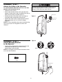
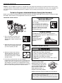
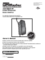
The Chamberlain Group, Inc.
845 Larch Avenue
Elmhurst, Illinois 60126-1196
www.liftmaster.com
®
DOOR OPERATOR
Model 3900PLD
pa
e with
tibl
Owner’s Manual
Se
De
tails
Co
m
For Light Duty Commercial Use Install On
Sectional Doors With Torsion Assemblies Only
r
eP
fo
age 13
■
Please read this manual and the enclosed safety materials carefully!
■
Fasten the manual near the door after installation.
door WILL NOT CLOSE unless The Protector System® and cable tension monitor are
connected and properly aligned.
■ The
■
Periodic checks of the operator are required to ensure safe operation.
■ The
■
model number label is located behind the hinged door of your operator.
Do NOT exceed 10 complete cycles of door operation per hour.
2 YEAR WARRANTY
Serial #
(located on electrical box cover)
Installation Date
TABLE OF CONTENTS
Introduction
2-5
Operation
Safety symbol review and signal word review . . . . . . . . . . 2
Planning . . . . . . . . . . . . . . . . . . . . . . . . . . . . . . . . . . . . . . 3
Preparing your door . . . . . . . . . . . . . . . . . . . . . . . . . . . . . . 4
Tools needed . . . . . . . . . . . . . . . . . . . . . . . . . . . . . . . . . . . 4
Specifications . . . . . . . . . . . . . . . . . . . . . . . . . . . . . . . . . . . 4
Carton inventory . . . . . . . . . . . . . . . . . . . . . . . . . . . . . . . . . 5
Hardware inventory . . . . . . . . . . . . . . . . . . . . . . . . . . . . . . 5
Assembly
Operation safety instructions . . . . . . . . . . . . . . . . . . . . . . 21
Using your door operator . . . . . . . . . . . . . . . . . . . . . . . . . 21
Care of your operator . . . . . . . . . . . . . . . . . . . . . . . . . . . . 22
Having a problem? (Troubleshooting) . . . . . . . . . . . . 23-24
Diagnostic Chart. . . . . . . . . . . . . . . . . . . . . . . . . . . . . . . . 25
Programming
Attach the collar to the operator. . . . . . . . . . . . . . . . . . . . . 6
Attach mounting bracket to the operator . . . . . . . . . . . . . . 6
7-16
Installation safety instructions . . . . . . . . . . . . . . . . . . . . . . 7
Position the operator . . . . . . . . . . . . . . . . . . . . . . . . . . . . . 7
Attach the emergency release rope and handle . . . . . . . . 8
Install power door lock (Not Provided) . . . . . . . . . . . . . . . . 8
Attach the cable tension monitor (Required) . . . . . . . . . . . 9
Install the single button control station. . . . . . . . . . . . . . . 10
Install the light (Not Provided) . . . . . . . . . . . . . . . . . . . . . 11
Electrical requirements. . . . . . . . . . . . . . . . . . . . . . . . . . . 12
Mount the Standby Power Unit (SPU) (Not Provided) . . . 13
Install The Protector System®. . . . . . . . . . . . . . . . . . . 14-16
Adjustment
26-28
To add or reprogram a hand-held
remote control (Not Provided) . . . . . . . . . . . . . . . . . . . . . 26
To erase all codes from motor unit memory . . . . . . . . . . 26
3-Button remote . . . . . . . . . . . . . . . . . . . . . . . . . . . . . . . . 26
The remote control battery . . . . . . . . . . . . . . . . . . . . . . . . 26
To add, program or change a keyless entry
PIN (Not Provided) . . . . . . . . . . . . . . . . . . . . . . . . . . . . . . 27
Programming remote light (Not Provided) . . . . . . . . . . . . 28
6
Installation
21-25
Repair Parts
29
Installation parts . . . . . . . . . . . . . . . . . . . . . . . . . . . . . . . . 29
Motor unit assembly parts . . . . . . . . . . . . . . . . . . . . . . . . 29
Accessories
Notes
Repair Parts and Service
30
31
Back Page
17-20
Program the travel limits . . . . . . . . . . . . . . . . . . . . . . . . . 17
Setting the force . . . . . . . . . . . . . . . . . . . . . . . . . . . . . . . . 18
Test the safety reversal system . . . . . . . . . . . . . . . . . . . . 19
Test The Protector System® . . . . . . . . . . . . . . . . . . . . . . . 19
Test cable tension monitor . . . . . . . . . . . . . . . . . . . . . . . . 20
To open door manually . . . . . . . . . . . . . . . . . . . . . . . . . . 20
INTRODUCTION
Safety Symbol Review
and Signal Word Review
This door operator has been designed and tested to offer safe service provided it is installed, operated, maintained and
tested in strict accordance with the instructions and warnings contained in this manual.
When you see these Safety Symbols and Signal Words on
the following pages, they will alert you to the possibility of
serious injury or death if you do not comply with the
warnings that accompany them. The hazard may come
from something mechanical or from electric shock. Read
the warnings carefully.
Mechanical
Electrical
When you see this Signal Word on the following pages, it
will alert you to the possibility of damage to your garage
door and/or the garage door operator if you do not comply
with the cautionary statements that accompany it. Read
them carefully.
2
Planning
• The torsion bar must extend at least 1" to 5"
(2.5 cm to 12 cm) past the bearing plate.
• An electric outlet is required within 6' (1.8 m) of the
installation area. If outlet does not exist, contact a
qualified electrician.
• Depending upon building construction, extension
brackets or wood blocks may be needed to install safety
reversing sensors.
• Alternate floor mounting of the safety reversing sensors
will require hardware not provided.
• A model 475LM EverChargeTM Standby Power Unit is
strongly recommended if there is no access door to the
garage, as this operator cannot be used in conjunction
with an external emergency release mechanism.
• Any gap between the floor and the bottom of the door
must not exceed 1/4" (6 mm). Otherwise the safety
reversal system may not work properly.
NOTE: Inspect the torsion bar while the door is raised and
lowered. It is important that there is no noticeable
movement up and down or left and right. If this type of
movement is not corrected, life of this operator will be
greatly reduced.
Survey your area to see if any of the conditions below
apply to your installation. Additional materials may be
required. You may find it helpful to refer back to this page
as you proceed with the installation of your operator.
Depending on your requirements, there are several
installation steps which may call for materials or hardware
not included in the carton.
This operator is compatible with:
• Doors that use a torsion bar, springs and a door no
more than 14' (4.2 m) high.
• 4"-6" (10 cm - 15 cm) drums, not to be used on tapered
drums over 6" (15 cm).
• High lift and standard lift sectional doors up to 14'
(4.2 m) high.
• Doors up to 18' (5.4 m) wide.
• Doors up to 180 sq. ft. (16.7 sq. m).
• 1" (2.5 cm) torsion bar only.
• Review or inspect proposed installation area. Operator
can be installed on left or right side of door. Select the
side that meets the requirements listed below.
- Must have minimum of 2-1/2" (6.4 cm) between the
wall and the center of the torsion bar.
- Must have minimum of 3" (7.6 cm) between the ceiling
and the center of torsion bar.
- Must have minimum of 8" (20.3 cm) between the side
wall (or obstruction) and the end of torsion bar.
Cable Tension
Monitor
Motor unit
Torsion Spring
Drum
Wall-mounted Single
Access Door Button Control Station
Safety
Reversing
Sensor
Safety
Reversing Sensor
Gap between floor
and bottom of door must not exceed 1/4" (6 mm).
3
Preparing your Door
Before you begin:
• Disable locks.
• Remove any ropes connected to door.
• Complete the following test to make sure your door is
balanced and is not sticking or binding:
1. Lift the door about halfway as shown. Release the
door. If balanced, it should stay in place, supported
entirely by its springs.
2. Raise and lower the door to see if there is any
binding or sticking.
If your door binds, sticks or is out of balance, call a
trained door systems technician.
3. Verify equal cable tension on each side of door.
Cable tension should remain equal during the entire
travel of the door.
To prevent possible SERIOUS INJURY or DEATH:
• ALWAYS call a trained door systems technician if door
binds, sticks or is out of balance. An unbalanced door may
not reverse when required.
• NEVER try to loosen, move or adjust door, door springs,
cables, pulleys, brackets or their hardware, ALL of which are
under EXTREME tension.
• Disable ALL locks and remove ALL ropes connected to door
BEFORE installing and operating door operator to avoid
entanglement.
To prevent damage to door and operator:
• ALWAYS disable locks BEFORE installing and operating the
operator.
• ONLY operate door operator at 120V, 60 Hz to avoid
malfunction and damage.
• Do NOT exceed 10 complete cycles of door operation per
hour.
Specifications
Volts . . . . . . . . . . . . . . . . . . . 120 Vac - 60 Hz, ONLY
Current . . . . . . . . . . . . . . . . . . . . . . . . . . . . . 1.0 AMP
Rated Load. . . . . . . . . . . . . . . . . 325 in.lb/sec
10 Cycles per Hour
Sectional Door
Tools needed
During assembly, installation and adjustment of the
operator, instructions will call for hand tools as illustrated
below.
1
Drill
2
Pliers
Wire Cutters
Tape Measure
3/16" and 1/8"
Hex Key Wrench
5/32", 3/16", 5/16"
and 3/4" Drill Bits
Stepladder
Pencil
1/4", 5/16" & 3/8" Sockets
and Wrench with 6" Extension
Claw Hammer
Screwdriver
Adjustable End Wrench
Torque Meter (not shown)
4
Needle Nose Pliers
Carton Inventory
Note that accessories will depend on the model
purchased. If anything is missing, carefully check the
packing material.
Your door operator is packaged in one carton which
contains the motor unit and the parts illustrated below.
2-Conductor Bell Wire
White & White/Red
Single Button Control Station
Safety Sensor
Bracket (2)
Collar with Screws
Mounting Bracket
Operator
Cable Tension
Monitor with 2-Conductor
Green/White Bell Wires
Safety Labels
and
Literature
The Protector System®
(2) Safety Reversing Sensors
(1 Sending Eye and 1 Receiving Eye)
with 2-Conductor White & White/Black
Bell Wire attached
Hardware Inventory
Self Tapping Screw #10-32 (2)
Drywall Anchor (2)
Drywall Anchor (Screw-In) (2)
Handle
Rope
Insulated Staples (30)
INSTALLATION HARDWARE
Hex Screw #14-10x1-7/8" (4)
Screw #6x-1-1/4" (2)
Machine Screw #6x1" (2)
Carriage Bolt 1/4"-20x1/2" (2)
Wing Nut 1/4"-20 (2)
Pan Head Screw 1/4"-20x1/2" (2)
Hex Head Screw #8x1" (2)
5
ASSEMBLY STEP 1
Attach the Collar to the Operator
To prevent possible SERIOUS INJURY or DEATH, the collar
MUST be properly tightened. The door may not reverse
correctly or limits may be lost due to collar slip.
To avoid installation difficulties, do not run the door
operator until instructed to do so.
• Loosen the collar screws.
• Attach collar to either the left or the right side of the
operator. Ensure that the collar is seated all the way on
motor shaft until stop is reached (Figure 1).
• Position the collar so that the screws are facing up
(accessible when attached to the torsion bar).
• Tighten both sides of collar screws equally to secure
collar to the motor unit (12-14 ft./lbs. of torque)
(Figure 2).
NOTE: For most installations the screws should be facing
up for easy access. Do not tighten set screws until
indicated.
Collar Screw
Figure 1
Set Screw
Collar Screw
Figure 2
ASSEMBLY STEP 2
Attach Mounting Bracket
to the Operator
• Loosely attach slotted side of mounting bracket to the
same side of the operator as the collar, using
self-threading screws provided.
NOTE: Do not tighten until instructed. Illustrations shown
are for left side installation.
RIGHT
WRONG
HARDWARE SHOWN ACTUAL SIZE
Screw
#10-32
Socket Wrench
6
WARNING
INSTALLATION
IMPORTANT INSTALLATION INSTRUCTIONS
WARNING
To reduce the risk of SEVERE INJURY or DEATH:
1. READ AND FOLLOW ALL INSTALLATION WARNINGS AND
INSTRUCTIONS.
2. Install door operator ONLY on properly balanced and
lubricated door. An improperly balanced door may not
reverse when required and could result in SEVERE INJURY
or DEATH.
3. ALL repairs to cables, spring assemblies and other hardware
MUST be made by a trained door systems technician
BEFORE installing operator.
4. Disable ALL locks and remove ALL ropes connected to door
BEFORE installing operator to avoid entanglement.
5 Mount emergency release handle no higher than 6 feet
(1.83 m) above floor.
6. NEVER connect door operator to power source until
instructed to do so.
7. NEVER wear watches, rings or loose clothing while installing
or servicing operator. They could be caught in door or
operator mechanisms.
8. Install wall-mounted door control:
• within sight of the door.
• out of reach of children at minimum height of 5 feet
(1.5 m).
• away from ALL moving parts of the door.
9. Place entrapment warning label on wall next to door control.
10. Place manual release/safety reverse test label in plain view
on inside of door.
11. Upon completion of installation, test safety reversal system.
Door MUST reverse on contact with a 1-1/2" (3.8 cm) high
object (or a 2x4 laid flat) on the floor.
INSTALLATION STEP 1
Position the Operator
To prevent possible SERIOUS INJURY or DEATH:
• Concrete anchors MUST be used if mounting bracket into
masonry.
• NEVER try to loosen, move or adjust door, springs, cables,
pulleys, brackets or their hardware, ALL of which are under
EXTREME tension.
• ALWAYS call a trained door systems technician if door
binds, sticks or is out of balance. An unbalanced door might
not reverse when required.
• Operator MUST be mounted at a right angle to the torsion
bar to avoid premature wear on the collar.
NOTE: For additional mounting options see
accessories page.
1. Close the door completely.
2. Slide the operator with collar over the end of the torsion
bar. Ensure that the collar does not touch the bearing
plate. Check to make sure the mounting bracket is
located on a solid surface such as wood, concrete or
door/flag bracket. Snug collar screws to help assure
proper alignment of operator. Mark the bracket holes. It
may be necessary to cut the torsion bar if it is too long
or damaged.
3. Loosen collar screws from torsion bar and remove the
operator. Drill 3/16" pilot holes at the marked locations.
Drill through steel plate if needed.
4. Reinstall the operator by sliding the collar over the
torsion bar until pilot holes align with bracket. Securely
tighten collar screws that attach to the torsion bar to
12-14 ft./lbs. of torque. Securely tighten both set screws
firmly, without damaging the motor unit.
5. Fasten bracket securely with 14-10x1-7/8" screws.
Tighten all mounting bracket hardware.
NOTE: The motor unit does not have to be flush to wall.
6. Use a staple to secure the antenna wire to prevent
antenna from being entangled in a door roller.
Operator
Torsion Bar
HARDWARE SHOWN ACTUAL SIZE
Staple
14-10x1-7/8" Hex Screw
7
INSTALLATION STEP 2
Attach the Emergency Release Rope
and Handle
To prevent possible SERIOUS INJURY or DEATH from a falling
door:
• If possible, use emergency release handle to disengage door
ONLY when door is CLOSED. Weak or broken springs or
unbalanced door could result in an open door falling rapidly
and/or unexpectedly.
• NEVER use emergency release handle unless doorway is
clear of persons and obstructions.
• Thread one end of the rope through the hole in the top
of the red handle so “NOTICE” reads right side up as
shown. Secure with an overhand knot at least 1"
(2.5 cm) from the end of the rope to prevent slipping.
• Thread the other end of the rope through the loop in the
emergency release cable.
• Adjust rope length so the handle is no higher than 6'
(1.83 m) above the floor. Secure with an overhand knot.
NOTE: If it is necessary to cut the rope, heat seal the cut
end with a match or lighter to prevent unraveling.
Motor Unit
Emergency
Release Cable
Overhand
Knot
Rope
Emergency
Release Handle
NOTI
CE
Overhand
Knot
INSTALLATION STEP 3
Install Power Door Lock
(Not Provided)
TOP
DRIL
L 5/16
"
DRIL
L 3/4"
132A2505
L 5/16
"
Garage
Door
Door Track
Track
Lock Template
TOP
DRIL
L 5/16
DRIL
Roller
HARDWARE SHOWN ACTUAL SIZE
Lock Screw
1/4-20 x 1/2" (2)
DRIL
Approx. 3"
(7.6 cm)
132A2505
The lock is used to prevent the door from being
manually opened once the door is fully closed.
1. Select a door roller to mount the lock above. Check
for clearance. If possible select a roller on the same
side of the door as the motor unit.
The second roller up from the bottom is ideal in
most installations.
2. Ensure rail surface is clean and adhere lock
template to achieve a 3" (7.6 cm) distance between
the center of the roller and the pin hole (Figure 1).
3. Drill holes as marked on the template.
4. Fasten power door lock to the outside of the garage
door track with hardware provided.
5. Run bell wire up wall to motor unit. Use insulated
staples to secure wire in several places.
6. Plug connector into the motor unit (Figure 2).
NOTE: Lock must be mounted within 10' of the
power head.
Staples
8
"
L 3/4"
DRIL
L 5/16
"
INSTALLATION STEP 4
Figure 1
Attach the Cable Tension Monitor
(Required)
Operator
This operator comes standard with the cable tension
monitor. It is supplied as a device to monitor the
cables for ANY slack that may occur and will reverse
the door when excessive slack is detected, eliminating
service calls.
The cable tension monitor MUST be connected and
properly installed before the door operator will move
in the down direction.
NOTE: The cable tension monitor is shipped for left side
installation. It is preferred that the cable tension monitor be
installed on the same side of the door as the operator.
If required, it can be mounted on the opposite side of door.
Remove the snap-ring holding the roller in place and
reassemble it on the opposite side of the cable tension
monitor.
1. Position the cable tension monitor as shown
(Figures 1 and 2). The cable tension monitor should be
located as close to the drum as possible.
NOTE: There must be no obstructions in the installation
area that prevent the cable tension monitor or the cable
itself from closing completely when slack is detected.
2. Make sure cable tension monitor is located over a wood
support member.
NOTE: If the cable tension monitor can not be mounted
into wood with the lag screws provided, it can be mounted
into 1/2" or greater drywall using the wall anchors (2) and
the #8 hex head screws (2) provided in the hardware bag.
3. Mark and drill 3/16" pilot holes for screws (pilot holes
are not required for anchors).
4. Attach the cable tension monitor to the wall using the
hardware provided. Make sure that the roller is on top of
the cable.
5. Run bell wire to operator. Use insulated staples to
secure wire in several places.
6. Connect bell wire to the green quick-connect terminals
(polarity is not important) (Figure 3).
NOTE: Cable must have tension through entire travel.
Make sure there is no slack in cable on opposite side of
door during normal operation. If this condition exists,
adjust cables as required.
Torsion Bar
Drum
Cable
2"-6"
(5 cm15 cm)
1/8"-1/4"
(3 mm-6 mm)
Cable
Tension
Monitor
Cable Tension
Monitor Roller
With Door Closed
Preferred Orientation
Figure 2
Wall
Drum
Cable
3/4" Min.
(18 mm Min.)
Figure 3
WHT/GRN
Cable Tension
Monitor
7/16" (11mm)
WHT/GRN
Strip wire 7/16" (11mm)
HARDWARE SHOWN ACTUAL SIZE
To insert or release wire,
push in tab with
screwdriver tip
#8 Hex Head Screw (2)
Screw #6 (2)
Staples
Wall Anchor (2)
9
INSTALLATION STEP 5
Install the Single Button
Control Station
To prevent possible SERIOUS INJURY or DEATH from
electrocution:
• Be sure power is not connected BEFORE installing door control.
• Connect ONLY to 24 VOLT low voltage wires.
To prevent possible SERIOUS INJURY or DEATH from a closing
door:
• Install door control within sight of door, out of reach of children
at a minimum height of 5 feet (1.5 m) and away from ALL
moving parts of door.
• NEVER permit children to operate or play with door control push
buttons or remote controls.
• Activate door ONLY when it can be seen clearly, is properly
adjusted and there are no obstructions to door travel.
• ALWAYS keep door in sight until completely closed. NEVER
permit anyone to cross path of closing door.
WHT/RED
WHT
Door Control
Connections
Single Button Control Station
10
IMPORTANT SAFETY INSTRUCTIONS
WARNING
To reduce the risk of SEVERE INJURY or DEATH:
1. This portable luminaire has a polarized plug (one blade is
wider than the other) as a feature to reduce the risk of
electric shock.
2. This plug will fit in a polarized outlet ONLY one way.
3. If the plug does not fit fully in the outlet, reverse the plug.
4. If it still does not fit, contact a qualified electrician.
5. NEVER use with an extension cord unless plug can be fully
inserted.
6. Do not alter the plug.
7. Light is intended for ceiling mount and indoor applications
ONLY.
INSTALLATION STEP 6
Install the Light (Not Provided)
To prevent possible OVERHEATING of the endpanel or light
socket:
• DO NOT use short neck or specialty light bulbs.
• DO NOT use halogen bulbs. Use ONLY incandescent.
To prevent damage to the operator:
• DO NOT use bulbs larger than 100W.
• ONLY use A19 size bulbs.
The remote light (operator light) is designed to plug directly
into a standard 120V outlet.
1. Install the hinge and latch clips. Clips slide in between
the metal plate and the plastic housing on each side of
the light base (Figure 1).
2. Select an appropriate location on the ceiling to mount
the light within 6' (1.8 m) of an electrical outlet so that
the cord and light are away from moving parts.
3. Install the ceiling mount plate with the screws provided.
Leave 1/8" (3.1 mm) of the thread exposed between the
ceiling and the screw head (Figure 2).
NOTE: If installing remote light (operator light) on drywall
and a ceiling joist can not be located, use wall anchors
provided. No pilot hole is required for wall anchors.
4. Determine the length of power cord needed to reach the
nearest outlet. Wind any excess cord around cord
retainer on the top side of the light base.
5. Install the light base by pushing onto the screws and
turning the base clockwise to lock the light in place.
6. Install two Type A19 incandescent or compact
fluorescent bulbs. 100 watt maximum per bulb,
200 watts total.
7. Install the light lens by hooking one end of the lens over
the hinge and pressing up on the other end to latch into
place (Figure 3).
8. Plug in the light to outlet.
9. Light must be programmed to operate. See
Programming Remote Light.
NOTE: Light will not operate until the unit is activated.
Figure 1
Light Clip Screw
Latch Clip
Light
Base
Plastic
Housing
Metal
Plate
Figure 2
Wall Anchors
Cord
Retainer
Scews
Figure 3
HARDWARE SHOWN ACTUAL SIZE
Light Clip Screw
#4-20 X 7/16" (2)
Light Clip
Screw
Screw #6x1" (2)
100 Watt (max)
Light
Lens
Wall Anchor (2)
11
Hinge Clip
INSTALLATION STEP 7
Electrical Requirements
To prevent possible SERIOUS INJURY or DEATH from
electrocution or fire:
• Be sure power is not connected to the operator, and
disconnect power to circuit BEFORE removing cover to
establish permanent wiring connection.
• Door installation and wiring MUST be in compliance with
ALL local electrical and building codes.
• NEVER use an extension cord, 2-wire adapter or change plug
in any way to make it fit outlet. Be sure the operator is
grounded.
To avoid installation difficulties, do not run the
operator at this time.
To reduce the risk of electric shock, your operator has a
grounding type plug with a third grounding pin. This plug
will only fit into a grounding type outlet. If the plug doesn’t
fit into the outlet you have, contact a qualified electrician to
install the proper outlet.
PERMANENT WIRING CONNECTION
RIGHT
WRONG
Flexible conduit
Green
Ground
Screw
If permanent wiring is required by your local code,
refer to the following procedure.
To make a permanent connection through the 7/8" hole in
the back of the operator (according to local code):
• Remove the operator from the torsion bar, remove cover
screws and set the cover aside.
• Remove the attached green ground terminal.
• Cut black and white wires and strip away 1/2" (1.3 cm)
of insulation, 3" (7.6 cm) before spade terminals.
• Remove the power cord from unit.
• Install a 90 conduit or flex cable adapter to the 7/8"
hole. Reinstall operator to torsion bar.
• Run wires through conduit, cut to proper length and
strip insulation.
• Attach with wire nuts provided.
• Properly secure wire under plastic ties so that wire does
not come in contact with moving parts.
• Reinstall the cover.
To avoid installation difficulties, do not run the
operator at this time.
Ground Tab
Ground Wire
Black Wire
From Power Cord
White Wire
From Power Cord
o
PERMANENT WIRING CONNECTION
Black Wire
Green Wire
90˚ Connector
12
White Wire
INSTALLATION STEP 8
Mount the Standby Power Unit (SPU)
(Not Provided)
475LM Standby
Power System
If the optional 475LM Standby Power Unit is part of this
installation it should be installed at this time.
• The SPU can be mounted to either the ceiling or a wall
within 3' (.9 m) of the motor unit.
• Position the SPU as desired to a structural support
(ceiling joist or wall stud).
• Attach the SPU to the support using the mounting holes
on either side of the SPU.
• Secure the SPU using the 1-1/2" lag screws (2) provided
with the SPU unit.
• Connect the SPU cord into the connector on the bottom
of the motor unit.
• Follow all instructions included with the 475LM unit to
test for proper operation and testing of the SPU.
SPU Cord
Connector
13
INSTALLATION STEP 7
Install The Protector System®
Be sure power is not connected to the door operator BEFORE
installing the safety reversing sensor.
To prevent SERIOUS INJURY or DEATH from a closing door:
• Correctly connect and align the safety reversing sensor. This
required safety device MUST NOT be disabled.
• Install the safety reversing sensor so beam is NO HIGHER
than 6" (15 cm) above floor.
The safety reversing sensor must be connected and
aligned correctly before the door operator will move in
the down direction. This is a required safety device
and cannot be disabled.
IMPORTANT INFORMATION ABOUT THE SAFETY
REVERSING SENSOR
When properly connected and aligned, the safety
reversing sensor will detect an obstacle in the path of its
electronic beam. The sending eye (with an amber indicator
light) transmits an invisible light beam to the receiving eye
(with a green indicator light). If an obstruction breaks the
light beam while the door is closing, the door will stop and
reverse to full open position, and the operator lights will
flash 10 times.
The units must be installed inside the building so that the
sending and receiving eyes face each other across the
door, no more than 6" (15 cm) above the floor. Either can
be installed on the left or right of the door as long as the
sun never shines directly into the receiving eye lens.
The mounting brackets are designed to clip onto the track
of sectional doors without additional hardware.
Safety Reversing Sensor
6" (15 cm) max. above floor
If it is necessary to mount the units on the wall, the
brackets must be securely fastened to a solid surface such
as the wall framing. Extension brackets (see accessories)
are available if needed. If installing in masonry
construction, add a piece of wood at each location to
avoid drilling extra holes in masonry if repositioning is
necessary.
The invisible light beam path must be unobstructed. No
part of the door (door tracks, springs, hinges, rollers or
other hardware) may interrupt the beam while the door is
closing.
Safety Reversing Sensor
6" (15 cm) max. above floor
Invisible Light Beam
Protection Area
Facing the door from inside the garage
14
INSTALLING THE BRACKETS
Be sure power to the operator is disconnected. Install
and align the brackets so the safety reversing sensors will
face each other across the door, with the beam no higher
than 6" (15 cm) above the floor. They may be installed in
one of three ways, as follows.
Figure 1
DOOR TRACK MOUNT (RIGHT SIDE)
Door
Track
Lip
Indicator
Light
Door track installation (preferred) (Figure 1):
• Slip the curved arms over the rounded edge of each
door track, with the curved arms facing the door. Snap
into place against the side of the track. It should lie flush,
with the lip hugging the back edge of the track, as shown
in Figure 1.
If your door track will not support the bracket securely, wall
installation is recommended.
Sensor
Bracket
Wall installation (Figure 2 and 3):
• Place the bracket against the wall with curved arms
facing the door. Be sure there is enough clearance for
the sensor beam to be unobstructed.
• If additional depth is needed, an extension bracket
(See Accessories) or wood blocks can be used.
• Use bracket mounting holes as a template to locate and
drill (2) 3/16" diameter pilot holes on the wall at each
side of the door, no higher than 6" (15 cm) above
the floor.
• Attach brackets to wall with lag screws (Not provided).
• If using extension brackets or wood blocks, adjust right
and left assemblies to the same distance out from the
mounting surface. Make sure all door hardware
obstructions are cleared.
Lens
e
id
Ins l
l
Wa
Figure 2
WALL MOUNT (RIGHT SIDE)
Fasten Wood Block to Wall with
Lag Screws (Not Provided)
Indicator
Light
Sensor
Bracket
Lag Screws
(Not Provided)
Lens
Figure 3
WALL MOUNT (RIGHT SIDE)
e
id
Ins l
l
Wa
Floor installation (Figure 4):
• Use wood blocks or extension brackets (See
Accessories) to elevate sensor brackets so the lenses
will be no higher than 6" (15 cm) above the floor.
• Carefully measure and place right and left assemblies at
the same distance out from the wall. Be sure all door
hardware obstructions are cleared.
• Fasten to the floor with concrete anchors as shown.
Extension
Bracket
(See Accessories)
(Provided with
Extension Bracket)
Sensor
Bracket
(Provided with
Extension
Bracket)
Lens
Figure 4
Indicator
Light
FLOOR MOUNT (RIGHT SIDE)
HARDWARE SHOWN ACTUAL SIZE
Carriage Bolt
1/4"-20x1/2"
Wing Nut
1/4"-20
Attach with
Concrete Anchors
(Not Provided)
ide
Ins ll
a
W
Staples
Lens
Indicator
Light
Sensor
Bracket
15
MOUNTING AND WIRING THE SAFETY REVERSING
SENSORS
• Slide a 1/4"-20x1/2" carriage bolt head into the slot on
each sensor. Use wing nuts to fasten safety reversing
sensors to brackets, with lenses pointing toward each
other across the door. Be sure the lens is not obstructed
by a bracket extension (Figure 5).
• Finger tighten the wing nuts.
• Run the wires from both safety reversing sensors to the
operator. Use insulated staples to secure wire to wall
and ceiling.
• Strip 7/16" (11 mm) of insulation from each set of wires.
Separate white and white/black wires sufficiently to
connect to the operator quick-connect terminals: white to
white and white/black to grey (Figure 6).
Figure 5
Wing Nut
1/4"-20
Carriage Bolt
1/4"-20x1/2"
Lens
TROUBLESHOOTING THE SAFETY REVERSING
SENSORS
1. If the sending eye indicator light does not glow steadily
after installation, check for:
• Electric power to the operator.
• A short in the white or white/black wires. These can
occur at staples, or at operator connections.
• Incorrect wiring between safety reversing sensors and
operator.
• A broken wire.
2. If the sending eye indicator light glows steadily but the
receiving eye indicator light doesn’t:
• Check alignment.
• Check for an open wire to the receiving eye.
3. If the receiving eye indicator light is dim, realign
either sensor.
NOTE: When the invisible beam path is obstructed or
misaligned while the door is closing, the door will reverse.
If the door is already open, it will not close.
ALIGNING THE SAFETY REVERSING SENSORS
• Plug in the operator. The indicator lights in both the
sending and receiving eyes will glow steadily if wiring
connections and alignment are correct.
The sending eye amber indicator light will glow regardless
of alignment or obstruction. If the green indicator light in
the receiving eye is off, dim, or flickering (and the invisible
light beam path is not obstructed), alignment is required.
• Loosen the sending eye wing nut and readjust, aiming
directly at the receiving eye. Lock in place.
• Loosen the receiving eye wing nut and adjust the safety
reversing sensor until it receives the sender’s beam.
When the green indicator light glows steadily, tighten the
wing nut.
Bell Wire
Motor unit
Figure 6
Bell Wire
To CableTension Monitor
Connect Wire to
Quick-Connect
Terminals
Sensor
Connections
WHT/RED
WHT
To Door Control
WHT/BLK
WHT
Quick-Connect Terminals
To insert or release wires, push
in ta