1
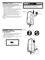
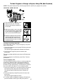
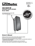
The Chamberlain Group, Inc.
845 Larch Avenue
Elmhurst, Illinois 60126-1196
www.liftmaster.com
®
DOOR OPERATOR
Model 3900PLD
pa
e with
tibl
Se
Owner’s Manual
De
tails
Co
m
For Light Duty Commercial Use Install On
Sectional Doors With Torsion Assemblies Only
r
eP
fo
age 13
■
Please read this manual and the enclosed safety materials carefully!
■
Fasten the manual near the door after installation.
■
The door WILL NOT CLOSE unless The Protector System® and cable tension monitor are
connected and properly aligned.
■
Periodic checks of the operator are required to ensure safe operation.
■
The model number label is located behind the hinged door of your operator.
■
Do NOT exceed 10 complete cycles of door operation per hour.
2 YEAR WARRANTY
Serial #
Installation Date
TABLE OF CONTENTS
Introduction
2-5
Operation
Safety symbol review and signal word review . . . . . . . . . . 2
Planning . . . . . . . . . . . . . . . . . . . . . . . . . . . . . . . . . . . . . . 3
Preparing your door . . . . . . . . . . . . . . . . . . . . . . . . . . . . . . 4
Tools needed . . . . . . . . . . . . . . . . . . . . . . . . . . . . . . . . . . . 4
Specifications . . . . . . . . . . . . . . . . . . . . . . . . . . . . . . . . . . . 4
Carton inventory . . . . . . . . . . . . . . . . . . . . . . . . . . . . . . . . . 5
Hardware inventory . . . . . . . . . . . . . . . . . . . . . . . . . . . . . . 5
Assembly
Operation safety instructions . . . . . . . . . . . . . . . . . . . . . . 21
Using your door operator . . . . . . . . . . . . . . . . . . . . . . . . . 21
Care of your operator . . . . . . . . . . . . . . . . . . . . . . . . . . . . 22
Having a problem? (Troubleshooting) . . . . . . . . . . . . 23-24
Diagnostic Chart. . . . . . . . . . . . . . . . . . . . . . . . . . . . . . . . 25
Programming
Attach the collar to the operator. . . . . . . . . . . . . . . . . . . . . 6
Attach mounting bracket to the operator . . . . . . . . . . . . . . 6
7-16
Installation safety instructions . . . . . . . . . . . . . . . . . . . . . . 7
Position the operator . . . . . . . . . . . . . . . . . . . . . . . . . . . . . 7
Attach the emergency release rope and handle . . . . . . . . 8
Install power door lock (Not Provided) . . . . . . . . . . . . . . . . 8
Attach the cable tension monitor (Required) . . . . . . . . . . . 9
Install the single button control station. . . . . . . . . . . . . . . 10
Install the light (Not Provided) . . . . . . . . . . . . . . . . . . . . . 11
Electrical requirements. . . . . . . . . . . . . . . . . . . . . . . . . . . 12
Mount the Standby Power Unit (SPU) (Not Provided) . . . 13
Install The Protector System®. . . . . . . . . . . . . . . . . . . 14-16
Adjustment
26-28
To add or reprogram a hand-held
remote control (Not Provided) . . . . . . . . . . . . . . . . . . . . . 26
To erase all codes from motor unit memory . . . . . . . . . . 26
3-Button remote . . . . . . . . . . . . . . . . . . . . . . . . . . . . . . . . 26
The remote control battery . . . . . . . . . . . . . . . . . . . . . . . . 26
To add, program or change a keyless entry
PIN (Not Provided) . . . . . . . . . . . . . . . . . . . . . . . . . . . . . . 27
Programming remote light (Not Provided) . . . . . . . . . . . . 28
6
Installation
21-25
Repair Parts
29
Installation parts . . . . . . . . . . . . . . . . . . . . . . . . . . . . . . . . 29
Motor unit assembly parts . . . . . . . . . . . . . . . . . . . . . . . . 29
Accessories
Notes
Repair Parts and Service
30
31
32
17-20
Program the travel limits . . . . . . . . . . . . . . . . . . . . . . . . . 17
Set the force . . . . . . . . . . . . . . . . . . . . . . . . . . . . . . . . . . . 18
Test the safety reversal system . . . . . . . . . . . . . . . . . . . . 19
Test The Protector System® . . . . . . . . . . . . . . . . . . . . . . . 19
Test cable tension monitor . . . . . . . . . . . . . . . . . . . . . . . . 20
To open door manually . . . . . . . . . . . . . . . . . . . . . . . . . . 20
INTRODUCTION
Safety Symbol Review
and Signal Word Review
This door operator has been designed and tested to offer safe service provided it is installed, operated, maintained and
tested in strict accordance with the instructions and warnings contained in this manual.
When you see these Safety Symbols and Signal Words on
the following pages, they will alert you to the possibility of
serious injury or death if you do not comply with the
warnings that accompany them. The hazard may come
from something mechanical or from electric shock. Read
the warnings carefully.
Mechanical
Electrical
When you see this Signal Word on the following pages, it
will alert you to the possibility of damage to your garage
door and/or the garage door operator if you do not comply
with the cautionary statements that accompany it. Read
them carefully.
2
Planning
• The torsion bar must extend at least 1" to 5"
(2.5 cm to 12 cm) past the bearing plate.
• An electric outlet is required within 6' (1.8 m) of the
installation area. If outlet does not exist, contact a
qualified electrician.
• Depending upon building construction, extension
brackets or wood blocks may be needed to install safety
reversing sensors.
• Alternate floor mounting of the safety reversing sensors
will require hardware not provided.
• A model 475LM EverChargeTM Standby Power Unit is
strongly recommended if there is no access door to the
garage, as this operator cannot be used in conjunction
with an external emergency release mechanism.
• Any gap between the floor and the bottom of the door
must not exceed 1/4" (6 mm). Otherwise the safety
reversal system may not work properly.
NOTE: Inspect the torsion bar while the door is raised and
lowered. It is important that there is no noticeable
movement up and down or left and right. If this type of
movement is not corrected, life of this operator will be
greatly reduced.
Survey your area to see if any of the conditions below
apply to your installation. Additional materials may be
required. You may find it helpful to refer back to this page
as you proceed with the installation of your operator.
Depending on your requirements, there are several
installation steps which may call for materials or hardware
not included in the carton.
This operator is compatible with:
• Doors that use a torsion bar, springs and a door no
more than 14' (4.2 m) high.
• 4"-6" (10 cm - 15 cm) drums, not to be used on tapered
drums over 6" (15 cm).
• High lift and standard lift sectional doors up to 14'
(4.2 m) high.
• Doors up to 18' (5.4 m) wide.
• Doors up to 180 sq. ft. (16.7 sq. m).
• 1" (2.5 cm) torsion bar only.
• Review or inspect proposed installation area. Operator
can be installed on left or right side of door. Select the
side that meets the requirements listed below.
- Must have minimum of 2-1/2" (6.4 cm) between the
wall and the center of the torsion bar.
- Must have minimum of 3" (7.6 cm) between the ceiling
and the center of torsion bar.
- Must have minimum of 8" (20.3 cm) between the side
wall (or obstruction) and the end of torsion bar.
Cable Tension
Monitor
Motor unit
Torsion Spring
Drum
Wall-mounted Single
Access Door Button Control Station
Safety
Reversing
Sensor
Safety
Reversing Sensor
Gap between floor
and bottom of door must not exceed 1/4" (6 mm).
3
Preparing your Door
Before you begin:
• Disable locks.
• Remove any ropes connected to door.
• Complete the following test to make sure your door is
balanced and is not sticking or binding:
1. Lift the door about halfway as shown. Release the
door. If balanced, it should stay in place, supported
entirely by its springs.
2. Raise and lower the door to see if there is any
binding or sticking.
If your door binds, sticks or is out of balance, call a
trained door systems technician.
3. Verify equal cable tension on each side of door.
Cable tension should remain equal during the entire
travel of the door.
To prevent possible SERIOUS INJURY or DEATH:
• ALWAYS call a trained door systems technician if door binds,
sticks or is out of balance. An unbalanced door may not
reverse when required.
• NEVER try to loosen, move or adjust door, door springs,
cables, pulleys, brackets or their hardware, ALL of which are
under EXTREME tension.
• Disable ALL locks and remove ALL ropes connected to door
BEFORE installing and operating door operator to avoid
entanglement.
To prevent damage to door and operator:
• ALWAYS disable locks BEFORE installing and operating the
operator.
• ONLY operate door operator at 120V, 60 Hz to avoid
malfunction and damage.
• DO NOT exceed 10 complete cycles of door operation per
hour.
Specifications
Volts . . . . . . . . . . . . . . . . . . . 120Vac - 60 Hz, ONLY
Current . . . . . . . . . . . . . . . . . . . . . . . . . . . . . 1.0 AMP
Rated Load. . . . . . . . . . . . . . . . . 325 in.lb/sec
10 Cycles per Hour
Sectional Door
Tools needed
During assembly, installation and adjustment of the
operator, instructions will call for hand tools as illustrated
below.
1
Drill
2
Pliers
Wire Cutters
Tape Measure
3/16" and 1/8"
Hex Key Wrench
5/32", 3/16", 5/16"
and 3/4" Drill Bits
Stepladder
Pencil
1/4", 5/16" & 3/8" Sockets
and Wrench with 6" Extension
Claw Hammer
Screwdriver
Adjustable End Wrench
Torque Meter (not shown)
4
Needle Nose Pliers
Carton Inventory
Note that accessories will depend on the model
purchased. If anything is missing, carefully check the
packing material.
Your door operator is packaged in one carton which
contains the motor unit and the parts illustrated below.
2-Conductor Bell Wire
White & White/Red
Single Button Control Station
Safety Sensor
Bracket (2)
Collar with Screws
Mounting Bracket
Operator
Cable Tension
Monitor with 2-Conductor
Green/White Bell Wires
Safety Labels
and
Literature
The Protector System®
(2) Safety Reversing Sensors
(1 Sending Eye and 1 Receiving Eye)
with 2-Conductor White & White/Black
Bell Wire attached
Hardware Inventory
Self Tapping Screw #10-32 (2)
Drywall Anchor (2)
Drywall Anchor (Screw-In) (2)
Handle
Rope
Insulated Staples (30)
INSTALLATION HARDWARE
Hex Screw #14-10x1-7/8" (4)
Screw #6x-1-1/4" (2)
Machine Screw #6x1" (2)
Carriage Bolt 1/4"-20x1/2" (2)
Wing Nut 1/4"-20 (2)
Pan Head Screw 1/4"-20x1/2" (2)
Hex Head Screw #8x1" (2)
5
ASSEMBLY STEP 1
Attach the Collar to the Operator
To prevent possible SERIOUS INJURY or DEATH, the collar
MUST be properly tightened. The door may not reverse
correctly or limits may be lost due to collar slip.
To avoid installation difficulties, do not run the door
operator until instructed to do so.
• Loosen the collar screws.
• Attach collar to either the left or the right side of the
operator. Ensure that the collar is seated all the way on
motor shaft until stop is reached (Figure 1).
• Position the collar so that the screws are facing up
(accessible when attached to the torsion bar).
• Tighten both sides of collar screws equally to secure
collar to the motor unit (12-14 ft./lbs. of torque)
(Figure 2).
NOTE: For most installations the screws should be facing
up for easy access. Do not tighten set screws until
indicated.
Collar Screw
Figure 1
Set Screw
Collar Screw
Figure 2
ASSEMBLY STEP 2
Attach Mounting Bracket
to the Operator
• Loosely attach slotted side of mounting bracket to the
same side of the operator as the collar, using
self-threading screws provided.
NOTE: Do not tighten until instructed. Illustrations shown
are for left side installation.
RIGHT
WRONG
HARDWARE SHOWN ACTUAL SIZE
Screw
#10-32
Socket Wrench
6
WARNING
INSTALLATION
IMPORTANT INSTALLATION INSTRUCTIONS
WARNING
To reduce the risk of SEVERE INJURY or DEATH:
1. READ AND FOLLOW ALL INSTALLATION WARNINGS AND
INSTRUCTIONS.
2. Install door operator ONLY on properly balanced and
lubricated door. An improperly balanced door may not
reverse when required and could result in SEVERE INJURY
or DEATH.
3. ALL repairs to cables, spring assemblies and other hardware
MUST be made by a trained door systems technician
BEFORE installing operator.
4. Disable ALL locks and remove ALL ropes connected to door
BEFORE installing operator to avoid entanglement.
5 Mount emergency release handle no higher than 6 feet
(1.83 m) above floor.
6. NEVER connect door operator to power source until
instructed to do so.
7. NEVER wear watches, rings or loose clothing while installing
or servicing operator. They could be caught in door or
operator mechanisms.
8. Install wall-mounted door control:
• within sight of the door.
• out of reach of children at minimum height of 5 feet
(1.5 m).
• away from ALL moving parts of the door.
9. Install the entrapment warning placard next to the control
station in a prominent location.
10. Place manual release/safety reverse test label in plain view
on inside of door.
11. Upon completion of installation, test safety reversal system.
Door MUST reverse on contact with a 1-1/2" (3.8 cm) high
object (or a 2x4 laid flat) on the floor.
INSTALLATION STEP 1
Position the Operator
To prevent possible SERIOUS INJURY or DEATH:
• Concrete anchors MUST be used if mounting bracket into
masonry.
• NEVER try to loosen, move or adjust door, springs, cables,
pulleys, brackets or their hardware, ALL of which are under
EXTREME tension.
• ALWAYS call a trained door systems technician if door
binds, sticks or is out of balance. An unbalanced door might
not reverse when required.
• Operator MUST be mounted at a right angle to the torsion
bar to avoid premature wear on the collar.
NOTE: For additional mounting options see
accessories page.
1. Close the door completely.
2. Slide the operator with collar over the end of the torsion
bar. Ensure that the collar does not touch the bearing
plate. Check to make sure the mounting bracket is
located on a solid surface such as wood, concrete or
door/flag bracket. Snug collar screws to help assure
proper alignment of operator. Mark the bracket holes. It
may be necessary to cut the torsion bar if it is too long
or damaged.
3. Loosen collar screws from torsion bar and remove the
operator. Drill 3/16" pilot holes at the marked locations.
Drill through steel plate if needed.
4. Reinstall the operator by sliding the collar over the
torsion bar until pilot holes align with bracket. Securely
tighten collar screws that attach to the torsion bar to
12-14 ft./lbs. of torque. Securely tighten both set screws
firmly, without damaging the motor unit.
5. Fasten bracket securely with 14-10x1-7/8" screws.
Tighten all mounting bracket hardware.
NOTE: The motor unit does not have to be flush to wall.
6. Use a staple to secure the antenna wire to prevent
antenna from being entangled in a door roller.
Operator
Torsion Bar
HARDWARE SHOWN ACTUAL SIZE
Staple
14-10x1-7/8" Hex Screw
7
INSTALLATION STEP 2
Attach the Emergency Release Rope
and Handle
To prevent possible SERIOUS INJURY or DEATH from a falling
door:
• If possible, use emergency release handle to disengage door
ONLY when door is CLOSED. Weak or broken springs or
unbalanced door could result in an open door falling rapidly
and/or unexpectedly.
• NEVER use emergency release handle unless doorway is
clear of persons and obstructions.
• Thread one end of the rope through the hole in the top
of the red handle so “NOTICE” reads right side up as
shown. Secure with an overhand knot at least 1"
(2.5 cm) from the end of the rope to prevent slipping.
• Thread the other end of the rope through the loop in the
emergency release cable.
• Adjust rope length so the handle is no higher than 6'
(1.83 m) above the floor. Secure with an overhand knot.
NOTE: If it is necessary to cut the rope, heat seal the cut
end with a match or lighter to prevent unraveling.
Motor Unit
Emergency
Release Cable
Overhand
Knot
Rope
Emergency
Release Handle
NOTI
CE
Overhand
Knot
INSTALLATION STEP 3
Figure 1
Install Power Door Lock
(Not Provided)
TOP
DRIL
L 5/16
"
DRIL
L 3/4"
132A2505
L 5/16
"
Garage
Door
Door Track
Track
Lock Template
TOP
DRIL
L 5/16
"
DRIL
L 3/4"
Roller
Figure 2
HARDWARE SHOWN ACTUAL SIZE
Lock Screw
1/4-20 x 1/2" (2)
DRIL
Approx. 3"
(7.6 cm)
132A2505
The lock is used to prevent the door from being
manually opened once the door is fully closed.
1. Select a door roller to mount the lock above. Check
for clearance. If possible select a roller on the same
side of the door as the motor unit.
The second roller up from the bottom is ideal in
most installations.
2. Ensure rail surface is clean and adhere lock
template to achieve a 3" (7.6 cm) distance between
the center of the roller and the pin hole (Figure 1).
3. Drill holes as marked on the template.
4. Fasten power door lock to the outside of the garage
door track with hardware provided.
5. Run bell wire up wall to motor unit. Use insulated
staples to secure wire in several places.
6. Plug connector into the motor unit (Figure 2).
NOTE: Lock must be mounted within 10' of the
power head.
Staples
8
DRIL
L 5/16
"
INSTALLATION STEP 4
Figure 1
Attach the Cable Tension Monitor
(Required)
Operator
This operator comes standard with the cable tension
monitor. It is supplied as a device to monitor the
cables for ANY slack that may occur and will reverse
the door when excessive slack is detected, eliminating
service calls.
The cable tension monitor MUST be connected and
properly installed before the door operator will move
in the down direction.
NOTE: The cable tension monitor is shipped for left side
installation. It is preferred that the cable tension monitor be
installed on the same side of the door as the operator.
If required, it can be mounted on the opposite side of door.
Remove the snap-ring holding the roller in place and
reassemble it on the opposite side of the cable tension
monitor.
1. Position the cable tension monitor as shown
(Figures 1 and 2). The cable tension monitor should be
located as close to the drum as possible.
NOTE: There must be no obstructions in the installation
area that prevent the cable tension monitor or the cable
itself from closing completely when slack is detected.
2. Make sure cable tension monitor is located over a wood
support member.
NOTE: If the cable tension monitor can not be mounted
into wood with the lag screws provided, it can be mounted
into 1/2" or greater drywall using the wall anchors (2) and
the #8 hex head screws (2) provided in the hardware bag.
3. Mark and drill 3/16" pilot holes for screws (pilot holes
are not required for anchors).
4. Attach the cable tension monitor to the wall using the
hardware provided. Make sure that the roller is on top of
the cable.
5. Run bell wire to operator. Use insulated staples to
secure wire in several places.
6. Connect bell wire to the green quick-connect terminals
(polarity is not important) (Figure 3).
NOTE: Cable must have tension through entire travel.
Make sure there is no slack in cable on opposite side of
door during normal operation. If this condition exists,
adjust cables as required.
Torsion Bar
Drum
Cable
2"-6"
(5 cm15 cm)
1/8"-1/4"
(3 mm-6 mm)
Cable
Tension
Monitor
Cable Tension
Monitor Roller
With Door Closed
Preferred Orientation
Figure 2
Wall
Drum
Cable
3/4" Min.
(18 mm Min.)
Figure 3
WHT/GRN
Cable Tension
Monitor
7/16" (11mm)
WHT/GRN
Strip wire 7/16" (11mm)
HARDWARE SHOWN ACTUAL SIZE
To insert or release wire,
push in tab with
screwdriver tip
#8 Hex Head Screw (2)
Screw #6 (2)
Staples
Wall Anchor (2)
9
INSTALLATION STEP 5
Install the Single Button
Control Station
To prevent possible SERIOUS INJURY or DEATH from
electrocution:
• Be sure power is not connected BEFORE installing door control.
• Connect ONLY to 24 VOLT low voltage wires.
To prevent possible SERIOUS INJURY or DEATH from a closing
door:
• Install door control within sight of door, out of reach of children
at a minimum height of 5 feet (1.5 m) and away from ALL
moving parts of door.
• NEVER permit children to operate or play with door control push
buttons or remote controls.
• Activate door ONLY when it can be seen clearly, is properly
adjusted and there are no obstructions to door travel.
• ALWAYS keep door in sight until completely closed. NEVER
permit anyone to cross path of closing door.
1. Remove the control station cover.
2. Fasten the control station to the wall at least 5’ (1.5 m)
above the ground. The installation surface must be
smooth and flat.
3. Select appropriate knockout and run the wires to the
operator.
4. Connect wires to the control station and replace the
control station cover.
5. Fasten the warning placards to the wall.
Factory installed
jumper must be in
place for proper
operation. Operator
will not function
without the jumper.
DO NOT EXCEED 10 DOOR OPERATIONS
PER HOUR.
FASTEN LABEL ADJACENT TO DOOR.
NE PAS FAIRE FONCTIONNER LA PORTE
PLUS DE 10 FOIS PAR HEURE.
FIXER L’ÉTIQUETTE PRÈS DE LA
PORTE.
132A2112-2
WHT/RED
WHT/RED
WARNING
WHT
WHT
Door Control
Connections
Moving Door Can Cause
Serious Injury or Death
Single Button
Button Control
Control Station
Station
Single
Keep Clear! Door May Move at any Time
Without Prior Warning
Do Not Let Children Operate the Door or Play
in the Door Area
Keep Door in Sight at all Times When Door is Moving
10
IMPORTANT SAFETY INSTRUCTIONS
WARNING
To reduce the risk of SEVERE INJURY or DEATH:
1. This portable luminaire has a polarized plug (one blade is
wider than the other) as a feature to reduce the risk of
electric shock.
2. This plug will fit in a polarized outlet ONLY one way.
3. If the plug does not fit fully in the outlet, reverse the plug.
4. If it still does not fit, contact a qualified electrician.
5. NEVER use with an extension cord unless plug can be fully
inserted.
6. DO NOT alter the plug.
7. Light is intended for ceiling mount and indoor applications
ONLY.
INSTALLATION STEP 6
Install the Light (Not Provided)
To prevent possible OVERHEATING of the endpanel or light
socket:
• DO NOT use short neck or specialty light bulbs.
• DO NOT use halogen bulbs. Use ONLY incandescent.
To prevent damage to the operator:
• DO NOT use bulbs larger than 100W.
• ONLY use A19 size bulbs.
The remote light (operator light) is designed to plug directly
into a standard 120V outlet.
1. Install the hinge and latch clips. Clips slide in between
the metal plate and the plastic housing on each side of
the light base (Figure 1).
2. Select an appropriate location on the ceiling to mount
the light within 6' (1.8 m) of an electrical outlet so that
the cord and light are away from moving parts.
3. Install the ceiling mount plate with the screws provided.
Leave 1/8" (3.1 mm) of the thread exposed between the
ceiling and the screw head (Figure 2).
NOTE: If installing remote light (operator light) on drywall
and a ceiling joist can not be located, use wall anchors
provided. No pilot hole is required for wall anchors.
4. Determine the length of power cord needed to reach the
nearest outlet. Wind any excess cord around cord
retainer on the top side of the light base.
5. Install the light base by pushing onto the screws and
turning the base clockwise to lock the light in place.
6. Install two Type A19 incandescent or compact
fluorescent bulbs. 100 watt maximum per bulb,
200 watts total.
7. Install the light lens by hooking one end of the lens over
the hinge and pressing up on the other end to latch into
place (Figure 3).
8. Plug in the light to outlet.
9. Light must be programmed to operate. See
Programming Remote Light.
NOTE: Light will not operate until the unit is activated.
Figure 1
Light Clip Screw
Latch Clip
Light
Base
Plastic
Housing
Metal
Plate
Figure 2
Wall Anchors
Cord
Retainer
Scews
Figure 3
HARDWARE SHOWN ACTUAL SIZE
Light Clip Screw
#4-20 X 7/16" (2)
Light Clip
Screw
Screw #6x1" (2)
100 Watt (max)
Light
Lens
Wall Anchor (2)
11
Hinge Clip
INSTALLATION STEP 7
Electrical Requirements
To prevent possible SERIOUS INJURY or DEATH from
electrocution or fire:
• Be sure power is not connected to the operator, and
disconnect power to circuit BEFORE removing cover to
establish permanent wiring connection.
• Door installation and wiring MUST be in compliance with
ALL local electrical and building codes.
• NEVER use an extension cord, 2-wire adapter or change plug
in ANY way to make it fit outlet. Be sure the operator is
grounded.
To avoid installation difficulties, do not run the
operator at this time.
To reduce the risk of electric shock, your operator has a
grounding type plug with a third grounding pin. This plug
will only fit into a grounding type outlet. If the plug doesn’t
fit into the outlet you have, contact a qualified electrician to
install the proper outlet.
PERMANENT WIRING CONNECTION
RIGHT
WRONG
Flexible Conduit
Green
Ground
Screw
If permanent wiring is required by your local code,
refer to the following procedure.
To make a permanent connection through the 7/8" hole in
the back of the operator (according to local code):
• Remove the operator from the torsion bar, remove cover
screws and set the cover aside.
• Remove the attached green ground terminal.
• Cut black and white wires and strip away 1/2" (1.3 cm)
of insulation, 3" (7.6 cm) before spade terminals.
• Remove the power cord from unit.
• Install a 90 conduit or flex cable adapter to the 7/8"
hole. Reinstall operator to torsion bar.
• Run wires through conduit, cut to proper length and
strip insulation.
• Attach with wire nuts provided.
• Properly secure wire under plastic ties so that wire does
not come in contact with moving parts.
• Reinstall the cover.
To avoid installation difficulties, do not run the
operator at this time.
Ground Tab
Ground Wire
Black Wire
From Power Cord
White Wire
From Power Cord
o
PERMANENT WIRING CONNECTION
Black Wire
Green Wire
90˚ Connector
12
White Wire
INSTALLATION STEP 8
Mount the Standby Power Unit (SPU)
(Not Provided)
475LM Standby
Power System
If the optional 475LM Standby Power Unit is part of this
installation it should be installed at this time.
• The SPU can be mounted to either the ceiling or a wall
within 3' (.9 m) of the motor unit.
• Position the SPU as desired to a structural support
(ceiling joist or wall stud).
• Attach the SPU to the support using the mounting holes
on either side of the SPU.
• Secure the SPU using the 1-1/2" lag screws (2) provided
with the SPU unit.
• Connect the SPU cord into the connector on the bottom
of the motor unit.
• Follow all instructions included with the 475LM unit to
test for proper operation and testing of the SPU.
SPU Cord
Connector
13
INSTALLATION STEP 9
Install The Protector System®
Be sure power is not connected to the door operator BEFORE
installing the safety reversing sensor.
To prevent SERIOUS INJURY or DEATH from a closing door:
• Correctly connect and align the safety reversing sensor. This
required safety device MUST NOT be disabled.
• Install the safety reversing sensor so beam is NO HIGHER
than 6" (15 cm) above floor.
The safety reversing sensor must be connected and
aligned correctly before the door operator will move in
the down direction. This is a required safety device
and cannot be disabled.
IMPORTANT INFORMATION ABOUT THE SAFETY
REVERSING SENSOR
When properly connected and aligned, the safety
reversing sensor will detect an obstacle in the path of its
electronic beam. The sending eye (with an amber indicator
light) transmits an invisible light beam to the receiving eye
(with a green indicator light). If an obstruction breaks the
light beam while the door is closing, the door will stop and
reverse to full open position, and the operator lights will
flash 10 times.
The units must be installed inside the building so that the
sending and receiving eyes face each other across the
door, no more than 6" (15 cm) above the floor. Either can
be installed on the left or right of the door as long as the
sun never shines directly into the receiving eye lens.
The mounting brackets are designed to clip onto the track
of sectional doors without additional hardware.
Safety Reversing Sensor
6" (15 cm) max. above floor
If it is necessary to mount the units on the wall, the
brackets must be securely fastened to a solid surface such
as the wall framing. Extension brackets (see accessories)
are available if needed. If installing in masonry
construction, add a piece of wood at each location to
avoid drilling extra holes in masonry if repositioning is
necessary.
The invisible light beam path must be unobstructed. No
part of the door (door tracks, springs, hinges, rollers or
other hardware) may interrupt the beam while the door is
closing.
Safety Reversing Sensor
6" (15 cm) max. above floor
Invisible Light Beam
Protection Area
Facing the door from inside the garage
14
INSTALLING THE BRACKETS
Be sure power to the operator is disconnected. Install
and align the brackets so the safety reversing sensors will
face each other across the door, with the beam no higher
than 6" (15 cm) above the floor. They may be installed in
one of three ways, as follows.
Figure 1
DOOR TRACK MOUNT (RIGHT SIDE)
Door
Track
Lip
Indicator
Light
Door track installation (preferred) (Figure 1):
• Slip the curved arms over the rounded edge of each door
track, with the curved arms facing the door. Snap into
place against the side of the track. It should lie flush, with
the lip hugging the back edge of the track, as shown in
Figure 1.
If your door track will not support the bracket securely,
wall installation is recommended.
Sensor
Bracket
Wall installation (Figure 2 and 3):
• Place the bracket against the wall with curved arms
facing the door. Be sure there is enough clearance for
the sensor beam to be unobstructed.
• If additional depth is needed, an extension bracket
(See Accessories) or wood blocks can be used.
• Use bracket mounting holes as a template to locate and
drill (2) 3/16" diameter pilot holes on the wall at each
side of the door, no higher than 6" (15 cm) above
the floor.
• Attach brackets to wall with lag screws (Not provided).
• If using extension brackets or wood blocks, adjust right
and left assemblies to the same distance out from the
mounting surface. Make sure all door hardware
obstructions are cleared.
Lens
ide
Ins l
l
Wa
Figure 2
WALL MOUNT (RIGHT SIDE)
Fasten Wood Block to Wall with
Lag Screws (Not Provided)
Indicator
Light
Sensor
Bracket
Lag Screws
(Not Provided)
Lens
Figure 3
WALL MOUNT (RIGHT SIDE)
e
id
Ins l
l
Wa
Floor installation (Figure 4):
• Use wood blocks or extension brackets (See
Accessories) to elevate sensor brackets so the lenses
will be no higher than 6" (15 cm) above the floor.
• Carefully measure and place right and left assemblies at
the same distance out from the wall. Be sure all door
hardware obstructions are cleared.
• Fasten to the floor with concrete anchors as shown.
Extension
Bracket
(See Accessories)
(Provided with
Extension Bracket)
Sensor
Bracket
(Provided with
Extension
Bracket)
Lens
Figure 4
Indicator
Light
FLOOR MOUNT (RIGHT SIDE)
HARDWARE SHOWN ACTUAL SIZE
Carriage Bolt
1/4"-20x1/2"
Wing Nut
1/4"-20
Attach with
Concrete Anchors
(Not Provided)
ide
Ins ll
a
W
Staples
Lens
Indicator
Light
Sensor
Bracket
15
MOUNTING AND WIRING THE SAFETY REVERSING
SENSORS
• Slide a 1/4"-20x1/2" carriage bolt head into the slot on
each sensor. Use wing nuts to fasten safety reversing
sensors to brackets, with lenses pointing toward each
other across the door. Be sure the lens is not obstructed
by a bracket extension (Figure 5).
• Finger tighten the wing nuts.
• Run the wires from both safety reversing sensors to the
operator. Use insulated staples to secure wire to wall
and ceiling.
• Strip 7/16" (11 mm) of insulation from each set of wires.
Separate white and white/black wires sufficiently to
connect to the operator quick-connect terminals: white to
white and white/black to grey (Figure 6).
Figure 5
Wing Nut
1/4"-20
Carriage Bolt
1/4"-20x1/2"
Lens
TROUBLESHOOTING THE SAFETY REVERSING
SENSORS
1. If the sending eye indicator light does not glow steadily
after installation, check for:
• Electric power to the operator.
• A short in the white or white/black wires. These can
occur at staples, or at operator connections.
• Incorrect wiring between safety reversing sensors and
operator.
• A broken wire.
2. If the sending eye indicator light glows steadily but the
receiving eye indicator light doesn’t:
• Check alignment.
• Check for an open wire to the receiving eye.
3. If the receiving eye indicator light is dim, realign
either sensor.
NOTE: When the invisible beam path is obstructed or
misaligned while the door is closing, the door will reverse.
If the door is already open, it will not close.
ALIGNING THE SAFETY REVERSING SENSORS
• Plug in the operator. The indicator lights in both the
sending and receiving eyes will glow steadily if wiring
connections and alignment are correct.
The sending eye amber indicator light will glow regardless
of alignment or obstruction. If the green indicator light in
the receiving eye is off, dim, or flickering (and the invisible
light beam path is not obstructed), alignment is required.
• Loosen the sending eye wing nut and readjust, aiming
directly at the receiving eye. Lock in place.
• Loosen the receiving eye wing nut and adjust the safety
reversing sensor until it receives the sender’s beam.
When the green indicator light glows steadily, tighten the
wing nut.
Bell Wire
Motor unit
Figure 6
Bell Wire
To CableTension Monitor
Connect Wire to
Quick-Connect
Terminals
Sensor
Connections
WHT/RED
WHT
To Door Control
WHT/BLK
WHT
Quick-Connect Terminals
To insert or release wires, push
in tab with screwdriver tip.
Safety Reversing Sensor
Sensor
Sensor Sensor
Safety Reversing
16
Invisible Light Beam
Protection Area
ADJUSTMENT STEP 1
Program the Travel Limits
Without a properly installed safety reversal system, persons
(particularly small children) could be SERIOUSLY INJURED or
KILLED by a closing door.
• NEVER learn forces or limits when door is binding or
sticking. Repair door first.
• Incorrect adjustment of door travel limits will interfere with
proper operation of safety reversal system.
• After ANY adjustments are made, the safety reversal system
MUST be tested. Door MUST reverse on contact with 1-1/2"
high (3.8 cm) object (or 2x4 laid flat) on floor.
Travel limits regulate the points at which the door will
stop when moving up or down.
Adjust the position of the door by using the black and
purple buttons. Black moves the door UP (open) and
purple moves the door DOWN (close).
LED
Figure 1
Black
Button
Purple
Button
To prevent damage to vehicles, be sure fully open door
provides adequate clearance.
Setting the UP position:
1. Press and hold the black button until the LED starts
flashing slowly, then release (Figure 2).
2. Push and hold the black button until the door reaches
the desired UP (open) position.
NOTE: Make sure the door opens high enough for your
vehicle.
3. Push the door control or programmed remote control.
This sets the UP (open) limit and begins closing the
door (Figure 3).
4. Immediately when the door begins to close, press and
release either the black or purple button. This will stop
the door.
Figure 2
BLACK
Push and hold
until the door
is at desired UP
position
PURPLE
Figure 3
Setting the DOWN position:
5. Push and hold the purple button until the door reaches
the desired DOWN (closed) position.
6. Once the door is closed, if there appears to be too
much pressure on the door, you may toggle the door
back and forth using the black and purple buttons to
reach the desired closed position.
7. Push the door control or programmed remote control.
This sets the DOWN (close) limit and the door should
open.
Figure 4
BLACK
Proceed to Set the Force.
Push either
button to stop
door at desired
DOWN position
PURPLE
17
ADJUSTMENT STEP 2
Set the Force
Without a properly installed safety reversal system, persons
(particularly small children) could be SERIOUSLY INJURED or
KILLED by a closing door.
• NEVER learn forces or limits when door is binding or
sticking. Repair door first
• Too much force on door will interfere with proper operation
of safety reversal system.
• After ANY adjustments are made, the safety reversal system
MUST be tested. Door MUST reverse on contact with 1-1/2"
high (3.8 cm) object (or 2x4 laid flat) on floor.
The force setting measures the amount of force
required to open and close the door.
1. Push the purple button twice to enter into the Force
Adjustment Mode. The LED will flash quickly.
2. Push the door control or programmed remote control.
The door will close (DOWN).
3. Push the door control or programmed remote control
again. The door will open (UP).
4. Push the door control or programmed remote control a
third time to close the door (DOWN).
The LED will stop flashing when the force has been
programmed.
The door must travel through a complete cycle, up and
down, in order for the force to be set properly. If the
garage door opener cannot open and close the door fully,
inspect the door to ensure that it is balanced properly and
is not sticking or binding.
If the door is not stopping exactly where you would like it,
repeat Program the Travel Limits.
Figure 1
LED
Black
Button
Figure 2
Push Purple button
twice to enter
unit into Force
Adjustment Mode
PURPLE
Purple
Button
Figure 3
18
BLACK
ADJUSTMENT STEP 3
Test the Safety Reversal System
Without a properly installed safety reversal system, persons
(particularly small children) could be SERIOUSLY INJURED or
KILLED by a closing door.
• Safety reversal system MUST be tested every month.
• If one control (force or travel limits) is adjusted, the other
control may also need adjustment.
• After ANY adjustments are made, the safety reversal system
MUST be tested. Door MUST reverse on contact with 1-1/2"
(3.8 cm) high object (or 2x4 laid flat) on the floor.
TEST
• With the door fully open, place a 1-1/2" (3.8 cm) board
(or a 2x4 laid flat) on the floor, centered under the door.
• Operate the door in the down direction. The door must
reverse on striking the obstruction. Upon successful
safety reversal test proceed to Adjustment Step 4.
ADJUST
• If the door stops on the obstruction, it is not traveling far
enough in the down direction. Complete Adjustment
Steps 1 and 2 Programming the Limits and Forces.
• Repeat the test.
• When the door reverses on the 1-1/2" (3.8 cm) board
(or 2x4 laid flat), remove the obstruction and run the
operator through 3 or 4 complete travel cycles to test
adjustment.
• If the unit continues to fail the Safety Reverse Test, call
for a trained door systems technician.
IMPORTANT SAFETY CHECK:
Test the Safety Reverse System after:
• Each adjustment of limits, or force controls.
• Any repair to or adjustment of the door
(including springs and hardware).
• Any repair to or buckling of the floor.
• Any repair to or adjustment of the operator.
1-1/2" (3.8 cm) board
(or a 2x4 laid flat)
ADJUSTMENT STEP 4
Test The Protector System®
Without a properly installed safety reversing sensor, persons
(particularly small children) could be SERIOUSLY INJURED or
KILLED by a closing door.
• Press the remote control push button to open the door.
• Place the operator carton in the path of the door.
• Press the remote control push button to close the door.
The door will not move more than an inch, and the
operator lights will flash.
The door operator will not close from a remote if the
indicator light in either sensor is off (alerting you to the fact
that the sensor is misaligned or obstructed).
If the operator closes the door when the safety
reversing sensor is obstructed, do not operate the
door. Call for a trained door systems technician.
Safety Reversing Sensor
19
Safety Reversing Sensor
ADJUSTMENT STEP 5
Test Cable Tension Monitor
To prevent possible SERIOUS INJURY or DEATH from a falling
door:
• If possible, use emergency release handle to disengage door
ONLY when door is CLOSED. Weak or broken springs or
unbalanced door could result in an open door falling rapidly
and/or unexpectedly.
• NEVER use emergency release handle unless doorway is
clear of persons and obstructions.
If your cable tension monitor has been activated the
Indicator Light will blink 9 times. See (Figure 1) page 16.
ADJUSTMENT STEP 6
To Open the Door Manually
The door should be fully closed if possible. Pull down on
the emergency release handle until a click noise is heard
from the unit and lift the door manually. To reconnect the
door to the operator, pull down the emergency release
handle straight down a second time until a click noise is
heard from the unit. The door will reconnect on the next
UP or DOWN operation.
Test the emergency release:
• Make sure the door is closed.
• Pull the emergency release handle. The door should
then be able to be opened manually.
• Return the door to the closed position.
• Pull the emergency handle a second time.
• Reconnect the door to the operator.
Emergency
Release Handle
20
NOT
ICE
WARNING
OPERATION
IMPORTANT SAFETY INSTRUCTIONS
WARNING
To reduce the risk of SEVERE INJURY or DEATH:
1. READ AND FOLLOW ALL WARNINGS AND INSTRUCTIONS.
2. ALWAYS keep remote controls out of reach of children.
NEVER permit children to operate or play with door control
push buttons or remote controls.
3. ONLY activate door when it can be seen clearly, it is
properly adjusted and there are no obstructions to door
travel.
4. ALWAYS keep door in sight until completely closed. NO
ONE SHOULD CROSS THE PATH OF THE MOVING DOOR.
5. NO ONE SHOULD GO UNDER A STOPPED, PARTIALLY
OPENED DOOR.
6. If possible, use emergency release handle to disengage door
ONLY when door is CLOSED. Weak or broken springs or
unbalanced door could result in an open door falling rapidly
and/or unexpectedly.
7. NEVER use emergency release handle unless doorway is
clear of persons and obstructions.
Using Your Door Operator
Press and hold the push button on the Single Button
Control Station until the door starts to move.
When the operator is activated (with the safety
reversing sensor correctly installed and aligned)
1. If open, the door will close. If closed, it will open.
2. If closing, the door will reverse.
3. If opening, the door will stop.
4. If the door has been stopped in a partially open position,
it will close.
5. If obstructed while closing, the door will reverse. If the
obstruction interrupts the sensor beam, the operator
lights will blink for five seconds.
6. If obstructed while opening, the door will stop.
7. If fully open, the door will not close when the beam is
broken. The sensor has no effect in the opening cycle.
21
8. After ANY adjustments are made, the safety reversal
system MUST be tested.
9. Safety reversal system MUST be tested every month. Door
MUST reverse on contact with 1-1/2" (3.8 cm) high object
(or a 2x4 laid flat) on the floor.
10. ALWAYS KEEP DOOR PROPERLY BALANCED
(see page 3). An improperly balanced door may not reverse
when required and could result in SEVERE INJURY or
DEATH.
11. ALL repairs to cables, spring assemblies and other
hardware, ALL of which are under EXTREME tension,
MUST be made by a trained door systems technician.
12. ALWAYS disconnect electric power to door operator
BEFORE making ANY repairs or removing covers.
13.
SAVE THESE INSTRUCTIONS.
CARE OF YOUR OPERATOR
MAINTENANCE SCHEDULE
Once a Month
• Manually operate door. If it is unbalanced or binding, call
a trained door systems technician.
• Check to be sure door opens & closes fully. Adjust limits
and/or force if necessary (see Adjustment Steps
1 and 2).
• Repeat the safety reverse test. Make any necessary
adjustments (see Adjustment Step 3).
Once a Year
• Oil door rollers, bearings and hinges. The operator does
not require additional lubrication. Do not grease the door
tracks.
22
HAVING A PROBLEM?
(TROUBLESHOOTING)
1. The operator doesn’t operate from either the Door
Control or the remote control:
• Does the operator have electric power? Plug a lamp
into the outlet. If it doesn’t light, check the fuse box
or the circuit breaker. (Some outlets are controlled by
a wall switch.)
• Is there a build-up of ice or snow under the door?
The door may be frozen to the ground. Remove any
restriction.
• The door spring may be broken. Have it replaced
(see page 3 for reference).
6. The door doesn’t open completely:
• Is something obstructing the door? Is it out of
balance, or are the springs broken? Remove the
obstruction or repair the door.
7. The door opens but won't close:
• Check cable tension monitor (see installation step 4).
• Check the safety reversing sensor. See Installation
Step 9.
• See Adjustment Step 2. For an existing installation,
see below.
Repeat the safety reverse test after the adjustment
is complete.
2. Operator operates from the remote, but not from
the Single Button Control Station:
• Are the wiring connections correct? Review
Installation Step 5.
8. The door reverses for no apparent reason:
• Check cable tension monitor (see installation step 4).
• Is something obstructing the door? Pull the
emergency release handle. Operate the door
manually. If it is unbalanced or binding, call a trained
door systems technician.
• Clear any ice or snow from the floor area where the
door closes.
• Review Adjustment Step 2.
Repeat safety reverse test after adjustments.
3. The door operates from the Single Button Control
Station, but not from the remote control:
• Program the operator to match the remote control
code. (Refer to instructions on the motor unit panel.)
Repeat with all Remotes.
4. The remote control has short range:
• Check to be sure the antenna on the side or back
panel of operator extends fully downward.
• Some installations may have shorter range due to a
metal door, foil backed insulation, or metal siding.
9. The door reverses for no apparent reason:
• Check the safety reversing sensor. Remove any
obstruction or align the receiving eye. See Installation
Step 9.
5. The door opens and closes by itself:
• Be sure that all remote control push buttons are off.
• Remove the bell wire from the door control terminals
and operate from the remote only. If this solves the
problem, the single button control station is faulty
(replace), or there is an intermittent short on the wire
between the control console and the motor unit.
• Clear memory and re-program all remote controls.
10. The operator strains to operate door:
• The door may be out of balance or the springs may
be broken. Close the door and use the emergency
release handle to disconnect the door. Open and
close the door manually. A properly balanced door
will stay in any point of travel while being supported
entirely by its springs. If it does not, disconnect the
operator and call a trained door systems technician.
11. The operator motor hums briefly, then won’t work:
• The door springs may be broken. See above.
23
Having a Problem? (Continued)
12. The operator won't operate due to power failure:
• Use the emergency release handle to disconnect the
door. The door can be opened and closed manually.
When power is restored, pull manual release a
second time.
• If a Standby Power Unit is connected, the operator
should be able to operate up to 20 times without
power.
13. Door loses limits.
• Collar not tightened securely. Tighten collar
(see Assembly Steps 1 and 2) and reprogram limits
(see Adjustment Step 1).
14. The operator moves when the door is in operation:
• Some minor movement is normal for this product. If it
is excessive the collar will wear prematurely.
• Check to make sure the torsion bar is not moving
left/right excessively.
• Check to make sure the torsion bar is not visibly
moving up and down as it rotates.
• Check that the operator is mounted at a right angle
to the jackshaft. If not, move the position of the
mounting bracket.
24
Motor
Unit
Installed
Safety Reversing
Sensor
“Learn”
Button LED
or Diagnostic
LED
“Learn”
Button
Your garage door operator is programmed with selfdiagnostic capabilities. The “Learn” button/diagnostic LED will
flash a number of times then pause signifying it has found a
potential issue. Consult Diagnostic Chart below.
Diagnostic Chart
1 FLASH
Safety reversing sensors
wire open (broken or
disconnected).
OR
2 FLASHES
Safety reversing sensors
wire shorted or black/
white wire reversed.
3 FLASHES
Door control or
wire shorted.
4 FLASHES
Safety reversing sensors
slightly misaligned
(dim or flashing LED).
5 FLASHES
Motor overheated or
possible RPM sensor
failure. Unplug to reset.
9 FLASHES
Cable tension monitor
reversal.
Symptom: One or both of the Indicator lights on the safety reversing sensors
do not glow steady.
• Inspect sensor wires for a short (staple in wire), correct wiring polarity (black/white
wires reversed), broken or disconnected wires, replace/attach as needed.
• Disconnect all wires from back of motor unit.
• Remove sensors from brackets and shorten sensor wires to 1-2 ft (30-60 cm) from
back each of sensor.
• Reattach sending eye to motor unit using shortened wires. If sending eye indicator
light glows steadily, attach the receiving eye.
• Align sensors, if the indicator lights glow replace the wires for the sensors. If the
sensor indicator lights do not light, replace the safety reversing sensors.
Symptom: LED is not lit on door control.
• Inspect door control/wires for a short (staple in wire), replace as needed.
• Disconnect wires at door control, touch wires together. If motor unit activates,
replace door control.
• If motor unit does not activate, disconnect door control wires from motor unit.
Momentarily short across red and white terminals with jumper wire. If motor unit
activates, replace door control wires.
Symptom: Sending indicator light glows steadily, receiving indicator light is
dim or flashing.
• Realign receiving eye sensor, clean lens and secure brackets.
• Verify door track is firmly secured to wall and does not move.
Symptom: Motor has overheated; the motor unit does not operate = Motor unit
hums briefly; RPM Sensor = Short travel 6-8" (15-20 cm).
• Unplug unit to reset. Try to operate motor unit, check diagnostic code.
• If it is still flashing 5 times and motor unit moves 6-8" (15-20 cm), replace
RPM sensor.
• If motor unit doesn’t operate, motor unit is overheated. Wait 30 minutes and retry. If
motor unit still will not operate replace logic board.
Symptom: Door reverses while closing.
• Check for possible door obstructions and remove.
• Check that the cable tension monitor is properly connected to the operator.
• Replace the cable tension monitor.
25
PROGRAMMING
NOTICE: If this Security✚® door operator is operated with a non-rolling code transmitter, the technical measure in the
receiver of the door operator, which provides security against code-theft devices, will be circumvented. The owner of the
copyright in the door operator does not authorize the purchaser or supplier of the non-rolling code transmitter to
circumvent that technical measure.
To Add or Program a Hand-held Remote Control (Not Provided)
Below are instructions for programming your operator to operate with optional Security✚® 315 MHz remote controls. A
maximum of eight Security✚® 315 MHz remote controls can be programmed to work with your operator.
USING THE “LEARN” BUTTON
To Erase All Codes From
Motor Unit Memory
To deactivate any unwanted remote, first erase all
codes:
Press and hold the “learn” button on
motor unit until the learn indicator light
goes out (approximately 6-9 seconds).
All previous codes are now erased.
Reprogram each remote or keyless
entry you wish to use.
*3-Button Remote (315 MHz)
If provided with your door operator, the large button is
factory programmed to
operate it. Additional
buttons on any
Security✚® 3-Button
remote can be
programmed to operate
other Security✚® door
operators.
1. Press and release the purple “learn”
button on the motor unit. The learn
indicator light will glow steadily for
30 seconds.
2. Within 30 seconds, press and hold
the button on the hand-held remote*
that you wish to operate your door.
THE REMOTE CONTROL BATTERY
To prevent possible SERIOUS INJURY or DEATH:
• NEVER allow small children near batteries.
• If battery is swallowed, immediately notify doctor.
To reduce risk of fire, explosion or chemical burn:
• Replace ONLY with 3V2032 coin batteries.
• DO NOT recharge, disassemble, heat above 100°C (212°F)
or incinerate.
3. Release the button when the learn
indicator light blinks and shuts off
upon learning the remote control. If
the optional remote light is installed,
the light will blink.
4. If the safety reversing sensors are not installed or
misaligned, the door will not close from a hand-held
remote control. If this occurs, the door can be closed by
pressing and holding the push button on the Single
Button Control Station until the door has closed.
Releasing the push button prior to the door closing will
cause the door to reverse.
The lithium battery should
produce power for up to 5 years.
Battery
positive
To replace battery, use the visor
side up (+)
clip or screwdriver blade to pry
open the case as shown. Insert
battery positive side up (+).
Dispose of old battery properly.
Replace the battery with only 3V2032 coin cell batteries.
NOTICE: To comply with FCC and or Industry Canada rules (IC), adjustment or modifications of this
receiver and/or transmitter are prohibited, except for changing the code setting or replacing the
battery. THERE ARE NO OTHER USER SERVICEABLE PARTS.
Tested to Comply with FCC Standards FOR HOME OR OFFICE USE. Operation is subject to the
following two conditions: (1) this device may not cause harmful interference, and (2) this device
must accept any interference received, including interference that may cause undesired operation.
26
To Add, Program or Change a Keyless Entry PIN (Not Provided)
NOTE: The optional Keyless Entry must be programmed to operate your garage door operator.
USING THE “LEARN” BUTTON
1. Press and release the purple “learn”
button on motor unit. The learn
indicator light will glow steadily for
30 seconds.
2. Within 30 seconds, enter a four digit
personal identification number (PIN)
of your choice on the keypad. Then
press and hold the ENTER button.
3. Release the button when the learn
indicator light blinks and shuts off
upon learning the remote control. If
the optional remote light is installed,
the light will blink.
To change an existing, known PIN
If the existing PIN is known, it may be changed by one person
without using a ladder.
1. Press the four buttons for the present PIN, then press and
hold the # button.
The operator light will blink twice. Release the # button.
2. Press the new 4-digit PIN you have chosen, then
press Enter.
The motor unit lights will blink once when the PIN has been
learned.
Test by pressing the new PIN, then press Enter. The door
should move.
To set a temporary PIN
You may authorize access by visitors or service people with
a temporary 4-digit PIN. After a programmed number of
hours or number of accesses, this temporary PIN expires
and will no longer open the door. It can be used to close the
door even after it has expired. To set a temporary PIN:
1. Press the four buttons for your personal entry PIN (not the
last temporary PIN), then press and hold the ✽ button.
The operator light will blink three times. Release the
button.
2. Press the temporary 4-digit PIN you have chosen, then
press Enter.
The operator light will blink four times.
3. To set the number of hours this temporary PIN will work,
press the number of hours (up to 255), then press ✽.
27
Programming Remote Light (Not Provided)
The garage door operator remote light will need to be programmed to operate with the door operator. Follow the
instructions below to program the light.
1. Press the “learn button” on light until
LED comes ON.
2. Activate the door using the Single
Button Control Station (or hand-held
remote control or keyless entry, if
programmed).
3. It has learned the code and the light
turns on.
28
REPAIR PARTS
Installation Parts
8
5
1
3
2
4
7
NOT
ICE
KEY
NO.
PART
NO.
1
2
APBS 1
41A4582
3
4
5
6
41B4494-1
41A6104
41C0902
41A5034
6
DESCRIPTION
Single button control station
Emergency release rope & handle
assembly
2-Conductor bell wire - white & white/red
Cable tension monitor
Mounting bracket
Safety sensor kit (receiving and
sending eyes) with 3' (.9 m)
2-conductor bell wire attached
KEY
NO.
PART
NO.
DESCRIPTION
7
8
41A6388
41A5266-1
Collar with set screws (2)
Safety sensor brackets (2)
41A6298
114A3593
NOT SHOWN
Installation hardware bag
(includes hardware listed on page 5)
Owner’s manual
Motor Unit Assembly Parts
6
2
1
5
3
4
KEY
NO.
PART
NO.
DESCRIPTION
KEY
NO.
PART
NO.
DESCRIPTION
1
41DJ001
Logic board complete with plate
4
41A6095
Motor with bracket
2
41A6408
Absolute Encoder System
5
41B122
Power cord
3
41C168
Transformer
6
41A6348-3
Cover
29
ACCESSORIES
41A5281
Extension Brackets:
(Optional) For safety reversing
sensor installation onto the wall or
floor.
377LM
Keyless Entry with Security✚® :
Enables end user to operate door
operator from outside by entering a
password on a specially designed
keyboard. Also can add a temporary
password for visitors or service
persons. This temporary password
can be limited to a programmable
number of hours or entries.
380LM
475LM
Remote Work Light:
Enables homeowner to turn on a
work light from their car with their
door operator remote or from
anywhere in their home with an
additional LiftMaster Security✚®
remote.
30
EverCharge™ StandBy Power System:
Provides backup power to the model
3900 door operator.
480LM
Alternate Mounting Kit:
This kit allows the operator to be mounted
below the torsion bar in the case where
the torsion bar is not round or the normal
mounting area is obstructed.
41A6102
Power Door Lock:
Enables the end user to prevent the door
from being manually opened once closed.
NOTES
31
LIFTMASTER® SERVICE IS
ON CALL
HOW TO ORDER
REPAIR PARTS
OUR LARGE SERVICE ORGANIZATION
SPANS AMERICA
Selling prices will be furnished on request or parts will be
shipped at prevailing prices and you will be billed accordingly.
INSTALLATION AND SERVICE INFORMATION IS AS NEAR
AS YOUR TELEPHONE.
SIMPLY DIAL OUR TOLL FREE NUMBER:
WHEN ORDERING REPAIR PARTS, ALWAYS GIVE THE
FOLLOWING INFORMATION:
• PART NUMBER
• PART NAME
1-800-528-2806
• MODEL NUMBER
ADDRESS ORDERS TO:
THE CHAMBERLAIN GROUP, INC.
Technical Support Group
6050 S. Country Club Road
Tucson, Arizona 85706
www.liftmaster.com
For professional installation, parts and service, contact
your local LIFTMASTER/CHAMBERLAIN dealer. Look for him
in the Yellow Pages, or call our Service number for a list of
dealers in your area.
114A3593B
© 2010, The Chamberlain Group, Inc.
All Rights Reserved
SERVICE INFORMATION
TOLL FREE NUMBER:
1-800-528-2806