1
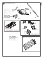
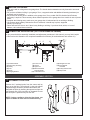
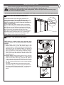
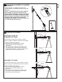
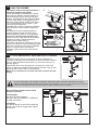
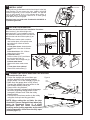
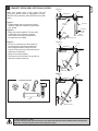
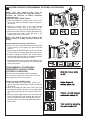
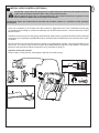
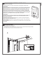
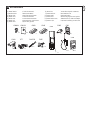
www.merlingo.com
MT60P
Sectional and Tilt Garage Door Opener
Installation and Operating Instructions
Owners Copy: Please keep these instructions for future reference
This manual contains IMPORTANT SAFETY information.
DO NOT PROCEED WITH THE INSTALLATION BEFORE READING THOROUGHLY.
WARNING
• Failure to comply with the following instructions may result in serious personal injury or property damage.
• Read and follow all instructions carefully.
• The garage door opener is designed and tested to offer safe service provided it is installed and
operated in strict accordance with the instructions in this manual.
These safety alert symbols mean WARNING : A possible risk to personal safety or
property damage exists.
Keep garage door balanced. Do not let the
garage door opener compensate for a binding or
sticking garage door. Sticking, binding or
unbalanced doors must be repaired before
installing this opener.
Do not wear rings, watches or loose clothing
while installing or servicing a garage door opener.
Frequently examine the door installation, in
particular cable, springs and mountings for signs of
wear, damage or imbalance. Do not use if repair or
adjustment is needed since springs and hardware
are under extreme tension and a fault can cause
serious personal injury.
To avoid serious personal injury from
entanglement, remove all ropes, chains and
locks connected to the garage door before
installing the door opener.
Installation and wiring must be in compliance with
your local building and electrical codes.
The safety reverse system test is very
important. Your garage door MUST reverse on
contact with a 40mm obstacle placed on the floor.
Failure to properly adjust the opener may result in
serious personal injury from a closing garage door.
Repeat the test once a month and make any
necessary adjustments.
This opener should not be installed in a damp
or wet space exposed to weather.
This appliance is not intended for use by persons
(including children) with reduced physical, sensory
or mental capabilities, or lack of experience and
knowledge, unless they have been given
supervision or instruction concerning use of the
appliance by a person responsible for their safety.
The Protector SystemTM must be used for all
installations where the closing force as
measured on the bottom of the door is over
400N (40kgf). Excessive force will interfere with the
proper operation of the Safety Reverse System or
damage the garage door.
After installation, ensure that the parts of the
door do not extend over public footpaths or
roads.
Install the wireless wall control (or any additional
wall control) in a location where the garage door
is visible, at a height of at least 1.5m and out of
the reach of children. Do not allow children to
operate push button(s) or transmitter(s). Serious
personal injury from a closing garage door may
result from misuse of the opener.
Permanently fasten the Warning Labels in
Prominent Places, adjacent to Wall Controls and
manual release mechanisms as a reminder of safe
operating procedures.
Activate opener only when the door is in full
view, free of obstructions and the opener is
properly adjusted. No one should enter or leave
the garage while the door is in motion.
Do not allow children to play near the door, or
door controls.
Disconnect electric power to the garage door
opener before making repairs or removing
covers.
KEEP THESE INSTRUCTIONS
Warning: If your garage has no service entrance door, a CM1702 outside quick release must be installed.
This accessory allows manual operation of the garage door from outside in case of power failure.
CONTENTS
PAGE
SAFETY INSTRUCTIONS . . . . . . . .1
DOOR TYPES . . . . . . . . . . . . . . . . .2
TOOLS REQUIRED . . . . . . . . . . . .2
HARDWARE PROVIDED . . . . . . .2-3
BEFORE YOU BEGIN . . . . . . . . . . .4
COMPLETED INSTALLATION . . . .4
ASSEMBLY . . . . . . . . . . . . . . . . .4-6
INSTALLATION . . . . . . . . . . . . . .7-11
ADJUSTMENT . . . . . . . . . . . . .12-13
WIRELESS PROGRAMMING .14-15
INSTALL THE PROTECTOR
SYSTEM (OPTIONAL) . . . . . . . . .13
SPECIAL FEATURES . . . . . . . . . .17
ACCESSORIES . . . . . . . . . . . . . . .18
REPLACEMENT PARTS . . . . .19-20
CARE OF YOUR OPENER . . . . . .20
MAINTAINING YOUR OPENER . .20
TROUBLESHOOTING . . . . . . . . . 21
OPERATION OF YOUR OPENER 22
SPECIFICATIONS . . . . . . . . . . . . .22
WARRANTY . . . . . . . . . . . . . . . . .23
1
START BY READING THESE IMPORTANT SAFETY INSTRUCTIONS
2
1 DOOR TYPES
A. One-Piece Door with Horizontal Track
Only
A
B. Sectional Door with curved track
C. One-Piece Door without track
C
B
To suit spring balanced sectional
doors up to 13.5m2 or spring
balanced Tilt doors up to 8.5m2.
2 TOOLS REQUIRED
1
2
8mm hex
head driver
10mm, 8mm,
4.5mm, 4mm
11mm, 13mm
3 HARDWARE PROVIDED
Installation Hardware:
(4) Large Clevis Pin (1)
(5) Carriage Bolts (2)
(6) Wood Screws (4)
(7) Clevis Pins (medium) (2)
(8) Hex Screws (4)
(9) Rope
(10) Handle
(11) Lock Washers (6)
(12) Nuts (6)
(13) 4mm Anchors (2)
(14) R-Clip (4)
(15) 8mm Anchors (4)
(16) Sheet Metal Screw (4)
4
7
11
15
5
8
12
9
6
16
10
NOTIC
E
14
13
(1) MT60P Opener
(2) Angled door arm
(3) Door mounting Bracket
(4) Straight door arm
(5) Chain pack and joiner
(6) Stop collar, nut & bolt
(7) Header bracket
(8) Pole kit adaptor
(9) Idler pulley assembly
(10) Trolley assembly
3
4 MT60P OPENER CARTON
2
1
4
3
9
6
5
7
10
3m Chain Pack and Joiner
8
Pole Adaptor Kit
POLE OPTIONS
2.75m Segmented pole kit
NOT PICTURED
2.75m or 3m one piece pole
Segmented Pole Pack
4
5 BEFORE YOU BEGIN:
1. Look at the wall or ceiling above the garage door. The header bracket must be securely fastened to structural
supports.
2. Do you have a finished ceiling in your garage? If so, a support bracket and additional fastening hardware (not
supplied) may be required.
3. Do you have an access door in addition to the garage door? If not, model CM1702 Outside Quick Release
Accessory is required. This accessory allows manual operation of the garage door from outside in case of power
failure.
4. Complete the following test to make sure your garage door is balanced and is not sticking or binding:
• Lift the door about halfway. Release the door. If balanced, it should stay in place, supported
entirely by its springs.
• Raise and lower the door to see if there is any binding or sticking. If your door binds, sticks, or is out of
balance, call a trained door technician.
6 COMPLETED INSTALLATION (TILT DOOR EXAMPLE SHOWN)
As you proceed with the assembly, installation and adjustment procedures in this manual, you may find it helpful
to refer back to this illustration of a completed installation for tilt doors (for sectional doors refer section 21).
3
2
1
4
7
9
11
13
6
15
5
12
8
DOOR
14
10
(1)
(2)
(3)
(4)
(5)
(6)
Header Bracket
Idler Pulley Assembly
Trolley
Pole
Chain
Hanging Bracket
NOTI
CE
(7) Power Cord
(8) Opener
(9) Light Lens
(10) Manual Release
Rope & Handle
(11) Curved Door Arm
ASSEMBLY SECTION
7 ASSEMBLE POLE PACK
Remove the 5 sectional poles from the carton and lay
them out on the floor. The end pole (i.e the pole without
a tapered edge) should be placed at the header end.
Assemble the poles by inserting the tapered end into the
non-Tapered end of the next pole as illustrated. Ensure
that each pole is pushed firmly into the next.
NOTE: If using a mallet to drive the joins home, use
a piece of timber at each end to minimise burring.
(12) Straight Door Arm
(13) Door Bracket
and Plate
(14) Trolley Release Arm
(15) Stop Collar
8 INSTALL THE TROLLEY AND IDLER PULLEY
Slide the trolley assembly (1) onto the pole (3) taking note
of the door direction arrow (fig 1). The trolley should be
located midway along the pole.
5
fig 1
DO
OR
2
Insert the pole (3) into the idler pulley assembly (2) as
illustrated.
1
3
9 INSTALL THE POLE ADAPTOR
1
Remove the four (factory fitted) washered screws (1).
THESE WASHERED SCREWS MUST BE USED TO FASTEN
THE POLE KIT ADAPTOR.
Place the pole adaptor bracket on the opener as illustrated
using the 4 washered screws (1) to fasten in place (tighten to
between 20-22Nm).
1
10 INSTALL THE STOP COLLAR AND POLE
Slide the stop collar (1) onto the pole (2) (opener
end). Fit the pole through the adaptor bracket (3) to
the opener, then fasten the stop collar above the
edge of the lens cover as illustrated.
Move the stop collar to the open limit on the pole,
set the stop collar back 25mm toward the opener
and fasten in place. Observe the absolute stop
position.
Absolute
minimum
stop collar
setting
2
3
1
1
6
11 INSTALL THE CHAIN
2
3
Fitting the Chain:
fig. 1
Wrap the chain around the idler pulley (1) and drive
sprocket (as illustrated in fig 1), ensuring the chain passes
through the trolley assembly (3).
NOTE: Locate the chain connector as illustrated above
approximately 300mm from the Idler pulley.
Additional Step for 2750mm Pole
All Chain kits supplied are for 3000mm poles. You will
need to remove the pre-measured section of chain for
use with the 2750mm pole option.
Locate the two removable links and remove the section
of chain between them. Once the section of chain has
been removed use one of the joiners to re-join the
shortened chain assembly.
Tighten the Chain
Once the chain has been installed, join the two
ends together using the connector. Tighten the
connector until the chain has no slack.
DO NOT OVER TIGHTEN!
Once the chain has been tensioned, tighten the
lock nuts.
NOTE: Use the tube of grease provided to
lubricate the chain and sprocket.
Connecting the chain
Lock nut
Rotate adjuster
Lock nut
7
INSTALLATION SECTION
Wear protective goggles when working overhead to protect your eyes from injury.
Disengage all existing garage door locks to avoid damage to the garage door.
To avoid serious personal injury from entanglement, remove all ropes connected to the garage
door before installing the opener.
It is recommended that the opener be installed 2.1m (7 feet) or more above the floor where space permits.
12 POSITION THE HEADER BRACKET
1
The header bracket must be rigidly fastened to a
structural support of the garage. Reinforce the wall or
ceiling with a 40mm (1-1/2") board if necessary.
Failure to comply may result in improper operation of
safety reverse system.
You can attach the header bracket either to the header
wall (1) or to the ceiling (3). Follow the instructions which
will work best for your particular requirements. With the
door closed, mark the vertical centerline (2) of the garage
door. Extend line onto header wall above the door.
Open door to highest point of travel. Draw an intersecting
horizontal line (4) on header wall 5 cm (2") above high
point to provide travel clearance for top edge of door.
Height depends on door type refer section 15.
4
2
3
13 INSTALL THE HEADER BRACKET
CEILING MOUNT ONLY
5
4
UP
2
LY
NG
ILI
CE
T ON
UN
MO
3
UP
1
5
50mm
(or 200mm)
A
5
1
2
CEILING MOUNT ONLY
UP
150mm
UP
NOTE: Refer to vertical centre and horizontal lines
created in section 12 for proper placement of header
bracket.
A. Wall mount: centre the header bracket (1) on the
vertical centre line (2) with the bottom edge of the
header bracket on the horizontal line (the horizontal line
should be 50 mm for Sectional Doors & Tracked Tilt
Doors and 200mm for One Piece Tilt doors, above the
spring (4) (with the arrow pointing toward the ceiling).
Mark all of the header bracket holes (5). Drill 4.5mm
(3/16") pilot holes and fasten the header bracket with
wood screws (3).
B. Ceiling mount: extend vertical centre line (2) onto the
ceiling. Centre the header bracket (1) on the vertical
mark no more than 150mm (6") from the wall. Mark all
of the header bracket holes (5). Drill 4.5mm (3/16") pilot
holes and fasten the header bracket with wood screws
(3). For concrete ceiling mount, use concrete anchors
provided.
The Idler Pulley Bracket will also need to be turned
upside down (fig 1). To do this remove the chain from
the pulley, twist the Idler bracket 1800 in to the upside
down position & reassemble the chain around the
pulley.
3
B
OR
DO
fig 1
BRACKET
8
14 ATTACH POLE ASSEMBLY TO HEADER
2
Position opener on garage floor below the
header bracket. Use packing material to protect
the cover.
NOTE: To enable the pole to clear sectional
door springs, it may be necessary to lift
opener onto a temporary support. The opener
must either be secured to a support or held
firmly in place by another person. Raise Pole
assembly until chain pulley and header
brackets come together. Join with clevis pin
(1). Insert R-clip (2) to secure.
1
1
2
15 POSITION THE OPENER
Pole
Header 50mm (2”)
Bracket above the highest
point of travel
SECTIONAL DOOR OR
TRACKED TILT DOOR
50mm spacer should
be used to determine
the correct mounting
position
Door
You will need a 50mm piece of timber or similar
spacer to gauge the distance between door and pole.
1. Raise the opener onto support.
2. Open the door completely, place a 50mm
spacer between the door and the pole
(as shown).
3. If the top section or panel hits the trolley when
you raise the door, pull down on the trolley arm
to disengage the opener. Leave the trolley in this
position until opener is fastened in place.
50mm (2”)
above the highest
point of travel
Pole
Header
Bracket
Door
50mm spacer should
be used to determine
the correct mounting
position
ONE PIECE TILT DOOR
You will need a 100mm (4”) piece of timber or similar
spacer to gauge the distance between door and pole.
1. Raise the opener onto support.
2. Open the door completely, place a 100mm
spacer between the door and the pole
(as shown).
3. The top of the door should be level with the top
of the opener. Do not position the opener more
than 50mm (2”) above this point.
Header
Bracket
200mm (8”)
above the highest
point of travel
100mm spacer should
be used to determine
the correct mounting
position
Door
Pole
9
16 HANG THE OPENER
The opener must be securely fastened to a
structural support of the garage.
Three representative installations are shown.
Yours may be different. Hanging brackets (1)
should be angled (Figure A) to provide rigid
support. On finished ceilings, (Figure B) attach
a sturdy metal bracket (not supplied) (4) to a
structural support before installing the opener.
For concrete ceiling mount, (Figure C), use
concrete anchors provided.
On each side of opener measure the distance
from the opener to the structural support (or
ceiling).
Cut both pieces of the hanging bracket to
required lengths. Flatten one end of each
bracket and bend or twist to fit the fastening
angles. Do not bend at the bracket holes.
Drill 4.5mm (3/16") pilot holes in the structural
supports (or ceiling). Attach brackets to
supports with wood screws (2).
Lift opener and fasten to hanging brackets with
screw, lock washer and nut (3). Check to make
sure pole is centered over the door. REMOVE
50mm or 100mm board. Operate door
manually. If door hits the pole, raise header
bracket.
A
B
2
2
4
1
1
3
3
2
1
2
3
C
5
1
2
3
5
2
3
17 ATTACH EMERGENCY RELEASE ROPE & HANDLE
Thread one end of rope (1) through hole in top of red handle so
"NOTICE" reads right side up as shown (3). Secure with an overhand
knot (2). Knot should be at least 25mm (1") from end of the rope to
prevent slipping.
Thread other end of rope through hole in release arm of the outer
trolley (4). Adjust rope length so that handle is less than 1.8m (6 feet)
above the floor. Secure with an overhand knot.
NOTE: If it is necessary to cut rope, heat seal cut end to prevent
fraying.
DOOR
2
4
1
NOT
ICE
3
2
DO NOT DISENGAGE THE OPENER TO MANUAL OPERATION WITH CHILDREN, PERSONS OR OTHER
OBJECTS INCLUDING MOTOR VEHICLES WITHIN THE DOORWAY: (The door is under significant tension and if
the door has developed a fault or incorrect tension, it may be unsafe and may fall rapidly.)
Door should be released in the closed
position if possible.
To Disengage:
Pull down on the red handle.
DO NOT USE THE HANDLE TO OPEN OR
CLOSE THE DOOR.
To Engage:
Pull the red handle up and back towards the
opener. The chain will engage when opener
is activated.
DOOR
DOOR
Engaged
Disengaged
18 INSTALL LIGHT
24V/21W Max.
Gently pull lens (2) downward until the lens hinge is in the fully
open position. Do not remove the lens. Install a 24V/21W
maximum light bulb (1) in the socket as shown. The light will
turn on and remain lit for 2-1/2 minutes when power is
connected. After 2-1/2 minutes it will turn off. To close, gently
push diffuser up until engaged.
2
Replace burnt out bulbs with Chamberlain 041A0079 or
reputable light bulbs.
19 FASTEN DOOR BRACKET
Sectional and One-Piece Door Installation Procedure:
Door bracket (1) has left and right side
fastening holes. If your installation requires
top and bottom fastening holes use both the
door bracket and door bracket plate (2) as
shown.
1. Center door bracket (with or without
door bracket plate, as required) at the
top inside face of door as shown.
Mark holes.
A. One-piece doors: locate bracket
at inside face of the door 0-100mm
down.
B. Sectional door: 150 - 250mm
below the top of the door.
2. A. Wooden doors
3
A
Drill 8mm holes (5/16") and fasten
the door bracket with nut,
lock washer, and carriage bolt (3).
B. Sheet metal doors
Fasten with sheet metal screws
(4).
C. One-piece door optional
Fasten with wood screws (5).
3
A. 0-100mm
B. 150-250mm
4
1
B
C
5
1
1
2
2
3
4
20 CONNECTING DOOR ARM ONE PIECE DOORS
Assemble the Door Arm:
• Fasten the straight and curved door arm
sections together to the longest possible
length (with a 2 or 3 hole overlap) (Figure 4).
• Make sure the garage door is fully closed.
Connect the straight door arm section to the
door bracket with the clevis pin.
• Secure with a ring fastener.
• Pull the emergency release handle disengage
the trolley by pulling straight down on the
emergency release cord. Slide the trolley
toward opener.
• Connect the curved arm section to the trolley
using the clevis pin and ring provided.
NOTE: When setting the up limits, the door
should NOT have a backward slant when fully
open (as illustrated Figure 5). A slight
backward slant will cause unnecessary
buckling and/or jerking operation as the door
is being opened or closed from the fully open
position (figure 5).
Figure 4
Door
Bracket
R-Clip
Lock
Washers
Nuts
Straight
Arm
Clevis Pin
Curved
Door Arm
Figure 5
Trolley
Correct Angle
Open Door
Door with
Backward Slant
(Incorrect)
10
1
11
21 CONNECT DOOR ARM SECTIONAL DOORS
Figure 1
Pulley
Make sure garage door is fully closed. Pull the
emergency release handle to disengage the trolley.
Slide the trolley assembly back 200mm from the idler
pulley.
Figure 1.
• Fasten straight door arm section to trolley
assembly using the hardware provided with
your opener.
Figure 2.
• Bring arm section together. Find two pairs
of holes that line up and join sections.
Select holes as far apart as possible to
increase door arm rigidity.
Trolley
200mm (8”) min.
Ring
Fastener
Clevis Pin
Emergency
Release
Handle
7
Door
Bracket
Straight
Door Arm
Curved Door Arm
6
Figure 3.
• If holes in curved arm are above holes in
the straight arm, disconnect straight arm
and cut approximately 150mm from the
solid end. Re-connect to trolley with end cut
end down as illustrated.
• Bring arm sections together.
• Find two pairs of holes that line up and join
with bolts, washers and nuts.
Figure 2
Trolley
Pulley
200mm (8”) min.
4
5
3
Door Bracket
Figure 3
Trolley
Pulley
200mm (8”) min.
HARDWARE PROVIDED
5
4
4
7
6
5
3
3
Cut this end
Connect Electric Power
TO AVOID INSTALLATION DIFFICULTIES, DO NOT RUN THE GARAGE DOOR OPENER UNTIL INSTRUCTED
TO DO SO. Connect to properly fused and earth power outlet.
12
ADJUSTMENT SECTION
22 SETTING THE LIMITS
Travel limits regulate the points at which the door will stop
when moving up or down. Follow the steps below to set
the limits.
1
2
3
NOTE: The door must be in the mid or closed position
to begin setting the limits.
1
Setting the limits:
1. Press and hold the black button (1) until the yellow
indicator (3) light starts flashing slowly then release.
2. Adjust the position of the door to the desired UP
position by using the black button. Black (1) moves the
door UP (open) and orange (2) moves the door DOWN
(close). Check to be sure the door opens high enough
for your vehicle to pass under.
3. Push the transmitter or door control. This sets the UP
(open) limit and begins closing the door.
Immediately press either the orange or the black
button. The door will stop.
4. Adjust the desired DOWN (close) limit position using
the black and orange buttons. Check to be sure the
door is fully closed without applying excessive pressure
on the rail (rail should not bow upwards and the chain
should not sag or droop below the rail). Push the
transmitter or door control. This sets the DOWN (close)
limit and begins opening the door.
5. Open and close the door with the transmitter or door
control 2 or 3 times (leave door in open position ready
for force setting).
2
3
merl
in+
4
NOTE: The force must now be set in order to
complete your installation (refer section 22).
5
merl
in+
23 SETTING THE FORCE
The force setting button is located behind the light lens of the
opener. The force setting regulates the amount of power
required to open and close the door.
1. Open the light lens. Locate the orange button (2).
2. Push the orange button (2) twice to enter unit into Force
Adjustment Mode. The LED (3) (indicator light) will flash quickly.
3. Push the programmed transmitter (4) or push bar on the door
control (if installed). The door will travel to the DOWN (close)
position. Push the transmitter (4) again, the door will travel to
the UP (open) position.
The LED (3) (indicator light) will stop flashing when the force has
been learned.
4
2
2
(2x)
The door must travel through a complete cycle, UP and DOWN,
in order for the force to be set properly. If the unit cannot open and
close your door fully, inspect your door to ensure that it is
balanced properly and is not sticking or binding.
The force MUST be learned in order to properly complete the
setting of the limits.
3
13
24 TEST THE SAFETY REVERSE SYSTEM
The safety reverse system test is important. Garage door must reverse on contact with a 40mm obstacle laid flat
on the floor. Failure to properly adjust opener may result in serious personal injury from a closing garage door.
Repeat test once a month and adjust as needed.
Procedure: Place a 40mm obstacle (1) laid flat on the floor under the garage door. Operate the door in the down direction.
The door must reverse on the obstacle. If the door stops on the obstacle, remove obstacle and repeat Setting the Limits and
Force Steps, then repeat safety reverse test.
When the door reverses on the 40mm obstacle, remove the obstacle and run the opener through a complete travel cycle.
Door must not reverse in closed position. If it does, repeat Setting the Limits and Force then repeat safety reverse test.
40mm
1
40mm
1
STANDARD INSTALLATION COMPLETE
25 INSTALL THE PROTECTOR SYSTEM™ (See accessories)
SAFETY FIRST!
Whilst Chamberlain have engineered safety features into your
garage door opener, we urge you to consider fitting IR Beams
to your new garage door opener. In many countries these
devices are compulsory to prevent serious injury or property
damage. For your own peace of mind and the safety of others
please install this inexpensive safety device.
Install this accessory for all installations on tilt doors, doors over 2.5m and when the closing force as
measured on the bottom of the door is over 400N (40kg).
After opener has been installed and adjusted, The Protector System™ accessory can be installed. Instructions
are included with this accessory.
The Protector System™ provides an additional measure of safety against a small child being caught
under a garage door. It uses an invisible beam which, when broken by an obstruction, causes a closing door to
open and prevents an open door from closing and is strongly recommended for homeowners with young
children.
NOTE: The opener will automatically detect the protector system when it is installed. The opener will not
close unless the sensors are aligned.
Connecting the Protector System
Locate the terminals on the back of the unit. Strip all
wires back about 10mm then twist the two white wires
and the two white/black wires together. Trim the twisted
wires to approximately 6mm. Use a small screwdriver or
pen to hold down the spring terminals, insert the
white/black wires into the grey terminal (4), then
terminate the white (only) wires into the white terminal
(3).
4. grey
3. white
white/black
wires twisted
together
white wires
twisted together
14
26 INSTALLING THE CM128 WIRELESS WALL BUTTON (OPTIONAL)
Carefully pry open the CM128 and locate the two screw for
mounting.
To attach to the wall, use the two screws and wall anchors provided if
mount to plaster wall (if using a recessed wall box do not use anchors).
NOTE: Tightening the wall mount screws will reduce clearance
between bracket and wall.
NOTE: Your CM128 Wireless door controller should be preprogrammed into your unit, you should only need to program
additional units.
Program the Wall control into the Rolling Code Receiver
Using the orange “LEARN” Button:
+
+
+
1. Press and hold down the button you wish to program to the
opener. The orange LED will flash to indiciate it is receiving signal from
the transmitter.
2. Press and release the “LRN” button.
3. The sourtesy LEDs will flash once.
Locate minimum 1.5m above
the floor.
Ensure the door is clear of obstruction, then test the transmitter.
27 WIRELESS PROGRAMMING (OPTIONAL ACCESSORIES)
Activate the opener only when door is in full view, free of obstruction and properly adjusted. No
one should enter or leave garage while door is in motion. Do not allow children to operate push
button(s) or remote(s). Do not allow children to play near the door.
NOTE: The transmitter(s) and wall button supplied with
your opener are factory programmed.
If you purchase additional transmitters, the garage door
opener must be programmed to accept the new remote
code.
Program the Receiver to Match Additional Transmitter
Codes:
Using the orange “LEARN” Button:
1. Press and hold down the transmitter button you wish to
program to the opener. The orange LED will flash to
indiciate it is receiving signal from the transmitter.
2. Press and release the “LRN” button.
3. The sourtesy LEDs will flash once.
Ensure the door is clear of obstruction, then test the
transmitter.
1
Using the Motion Detecting Control Panel
(optional accessory):
1. Press and hold the button on the hand-held remote that
you wish to operate your garage door (1).
2. While holding the remote button, press and hold the
LIGHT button on the Motion Detecting Control Panel (2).
3. Continue holding both buttons while you press the push
bar on the Motion Detecting Control Panel (all three
buttons are held) (3).
4. Release buttons when the opener light flashes. It has
learned the code. If the light bulb is not installed, two
clicks will be heard (4).
Now the opener will operate when the transmitter push
button is pressed. If you release the transmitter push button
before the opener light flashes, the opener has not learned
the code.
1
To Erase all Transmitter Codes:
To deactivate any unwanted remote, first erase all codes:
Press and hold the orange “learn” button on opener until
the learn indicator light goes out (approximately 6 seconds).
All previous codes are now erased. Reprogram each remote or keyless entry
you wish to use.
merl
3
2
merl
in+
3
2
in+
LOCK
LIGHT
LOCK
LIGHT
4
15
28 KEYLESS DEVICES PROGRAMMING (OPTIONAL ACCESSORIES)
NOTE: Your new Keyless Entry must be
programmed to operate your garage door opener.
Program the Receiver to Match Additional
Transmitter Code
Using the orange “LEARN” Button:
1. Press and release the orange “learn” button (1) on
opener. The learn indicator light will glow steadily for
30 seconds.
2. Within 30 seconds, enter a four digit personal
identification number (PIN) of your choice on the
keypad (2), then press and hold the ENTER button.
1
3
2
3. Release the button when the opener light flashes (3).
It has learned the code. If the light bulb is not
installed, two clicks will be heard.
NOTE: This method requires two people if the
Keyless Entry is already mounted outside the
garage.
Using the Motion Detecting Control Panel:
4. Enter a four digit personal identification number (PIN)
of your choice on the keypad, then press and hold
ENTER.
5. While holding the ENTER button, press and hold the
LIGHT button on the Motion Detecting Control Panel.
6. Continue holding the ENTER and LIGHT buttons
while you press the push bar on the Motion Detection
Control Panel (all three buttons are held).
7. Release buttons when the opener light flashes. It has
learned the code. If the light bulb is not installed, two
clicks will be heard.
LOCK
LIGHT
1
2
4
3
LOCK
LIGHT
LOCK
LIGHT
PROGRAMMING C379 WIRELESS
FINGERPRINT ACCESS SYSTEM
(OPTIONAL ACCESSORY)
Full instruction are available with this accessory.
Once you have enroled your user into the C379 you
can program the unit into your opener.
Using the orange “LEARN” Button:
1. Press and release the orange “learn” button (1) on
opener. The learn indicator light will glow steadily for
30 seconds.
2. Within 30 seconds, slide the cover of the C379 up as
illustrated (A). Swipe your finger on the reader head
at a steady speed (B) until the yellow led turnes on
(C).
3. When the opener light flashes (3). It has learned the
code. If the light bulb is not installed, two clicks will
be heard, ensure there are no obstructions in the
path of the door, then press the Send button (D) to
test the door.
16
29 INSTALL DOOR CONTROL (OPTIONAL)
Locate door control where the garage door is visible, away from door and door hardware and out
of the reach of children. Mount at least 1.5m (5 feet) above the floor
Serious personal injury from a moving garage door may result from misuse of opener. Do not
allow children to operate the door control or transmitter.
Permanently fasten the caution label to the wall near the door control as a reminder of safe operating
procedures.
There are 2 terminals (1) on the back of the door control (2). Strip about 6mm (1/4") of insulation from bell wire
(4). Separate wires enough to connect the white/red wire to RED terminal screw 1 and the white wire to WHT
terminal screw 2.
Fasten the door control to an inside garage wall with sheet metal screws (3) provided. Drill 4mm (5/32") holes and
use anchors (6) if installing into plasterboard wall. A convenient place is beside the service door and out of reach
of children.
Run the bell wire up the wall and across the ceiling to the garage door operator. Use insulated staples (5) to
secure wire. The receiver quick connect terminals are located behind the light lens of the operator. Connect the
bell wire to the terminals as follows: white/red to red (1) and white to white (2).
Operation of the Door Control
Press to open or close the door. Press again to stop the door while moving.
3
6mm
3
2
LOCK
LIGHT
2
1
1
2
WHT
-2
1
RED
RED
-1
WHT
4
3
4
5
3
4
6
17
30 USING THE MOTION DETECTING CONTROL PANEL
(optional accessory)
Press the push bar (1) to open or close the door. Press again to stop the door.
Light feature
Press the light button to turn the opener light on or off. It will not control the opener
lights when the door is in motion. If you turn it on and then activate the opener, the
light will remain on for 2 1/2 minutes. Press again to turn it off sooner. The 2 1/2
minute interval can be changed to 1-1/2, 3-1/2 or 4-1/2 minutes as follows: Press
and hold the Lock button until the light flashes (about 10 seconds). A single flash
indicates that the timer is reset to 1-1/2 minutes. Repeat the procedure and the light
will flash twice, resetting the timer to 2-1/2 minutes. Repeat again for 3-1/2 minute
interval, etc, up to a maximum of four flashes and 4-1/2 minutes.
Lock feature
Designed to prevent operation of the door from hand-held transmitters. However, the
door will open and close from the Door Control, the Outside Keyswitch and the
Keyless Entry Accessories.
To activate, press and hold the Lock button for 2 seconds. The push bar light will
flash as long as the Lock feature is on.
To turn off, press and hold the Lock button again for 2 seconds. The push bar light
will stop flashing.
The Lock feature will also turn off whenever the “LEARN” button on the opener panel
is activated.
LOCK
31 SPECIAL FEATURES
A. Door within a door connection
Open light lens. Locate auxiliary quick connect terminals 7 and 8. Remove factory installed
link. Insert bell wire into quick connect terminals 7 and 8.
A
8
7
LIGH
T
(1) Model CM844
(2) Model CM128
(3) Model C940
(4) Model C943
(5) Model C945
(6) Model C98
(7) Model C840
18
32 ACCESSORIES
4 Channel transmitter
Wireless Wall Button
Single-Channel transmitter
3-Channel transmitter
3-Channel Mini transmitter
Motion Detecting Control Panel
Keyless Entry System
CM844
1
C840
C940
CM128
2
C943
3
CM1702
C77
The Protector SystemTM IR Beams
Quick Release Lock
Outside Keyswitch
Wireless Fingerprint Access System
433MHz Antenna, Cable and Adaptor
LCD Motion Detecting Control Panel
(8) Model C77
(9) Model CM1702
(10) Model 760E
(11) Model C379
(12) Model ANT4X-1LM
(13) Model C198
C379
C945
C98
LOCK
4
5
LIGHT
6
C198
760E
ENROLL
SEND
9
7
10
ENROLL
PASS
FAIL
READY
RETRY
8
12
11
13
19
33 REPLACEMENT PARTS
NOT
ICE
041A2828
178B0086B
012B0905
178B0034B
E
AS
RE
IL G 3A4
.8
NO
RA
012B0906
083A0011-1
002A1658
002A1659
001A7350
012B0415
PDR30005
2.75m Segmented Pole Pack
001A5643-23
001A6829
184A0242
142A0229
012A0928
142A0230
20
34 REPLACEMENT PARTS
158A0049
041A5797
041A5908
041A5735C
041A0079
041D0577
204C0240-2
If the supply cord is damaged, it must be
replaced by the manufacturer, its service
agent or similarly qualified persons
in order to avoid hazard.
031D0587
108C0082
CARE OF YOUR OPENER
When properly installed your opener will operate with minimal maintenance. The opener does not require
additional lubrication.
Limit and Force Adjustments: These adjustments must be checked and properly set when opener is
installed. Weather conditions may cause some minor changes in the door operation, requiring some readjustments, particularly during the first year of operation.
Refer to the limit and force adjustments in sections 22 & 23. Follow the instructions carefully and repeat the
safety reverse test after any adjustment.
Transmitter:The portable transmitter may be secured to a car sun visor with the clip provided. Additional
remotes can be purchased at any time for use in all vehicles using garage. Refer to Accessories. Any new
remotes must be programmed into the opener.
Transmitter Battery: If transmission range decreases replace the battery.
To Change Battery: To replace batteries, use the visor clip or screwdriver blade to pry open the case. Insert
batteries positive side up. To replace cover, snap shut along both sides. Do not dispose of the old battery with
household waste.
MAINTENANCE OF YOUR OPENER
Once a Month:
• Repeat safety reverse test. Make any necessary adjustments.
• Manually operate door. If it is unbalanced or binding, call for professional garage door service.
• Check to be sure door opens and closes fully. Adjust Limits and/or Force if necessary.
Once a Year:
Oil door rollers, bearings and hinges. Do not grease the door tracks.
Clean and lubricate the pole, chain and trolley. The opener does not require additional lubrication.
21
TROUBLE SHOOTING
1. Opener doesn't operate from either door control or
remote:
• Does the opener have electric power? Plug lamp into outlet. If
it doesn't light, check the fuse box or the circuit breaker.
(Some outlets are controlled by a wall switch.)
• Have you disengaged all door locks? Review installation
instruction warnings on page 1.
• Is there a build-up of ice or snow under door? The door may
be frozen to ground. Remove any obstruction.
• The garage door spring may be broken. Have it replaced.
2. Opener operates from remote but not from door control:
• Is door control button lit? If not, remove the bell wire from the
opener terminals. Short the red and white terminals by
touching both terminals at the same time with a piece of wire.
If the opener runs, check for a faulty wire connection at the
door control, a short under the staples, or a broken wire.
• Are wiring connections correct? Review step 29.
3. Door operates from door control but not from remote:
• Replace battery if necessary.
• If you have two or more remotes and only one operates,
review Program Your Opener, Remote and Keyless Entry
steps 27 and 28.
• Is the door control button flashing? The opener is in lock
mode. If you have a Motion Detecting Control Panel, push
and hold the Lock button for 2 seconds. The door control
button will stop flashing.
4. Remote has short range:
• Is battery installed?
• Change the location of the transmitter on the car.
• A metal garage door, foil-backed insulation or metal siding will
reduce the transmission range.
5. Door reverses for no apparent reason and opener light
doesn't flash:
• Is something obstructing the door? Pull manual release
handle. Operate door manually. If it is unbalanced or binding,
call for professional garage door service.
• Clear any ice or snow from garage floor area where garage
door closes.
• Repeat Setting Limits and Force, see adjustment steps 22
and 23.
Repeat safety reverse test after adjustment is complete.
6. Door reverses for no apparent reason and opener light
flashes for 5 seconds after reversing:
Check The Protector System™ (if you have installed this
accessory). If the light is flashing, correct alignment.
7. The garage door opens and closes by itself:
Make sure remote push button is not stuck "on". For peace of
mind, install an Open Door Monitor so you can check the status
of your door.
8. Door stops but doesn't close completely:
Repeat Setting the Limits, see adjustment step 22.
Repeat safety reverse test after any adjustment of door arm
length, close force or down limit.
9. Door opens but won't close:
• Check The Protector System™ (if you have installed this
accessory). If the light is flashing, correct alignment.
• If opener light does not flash and it is a new installation,
repeat Setting the Limit and Force steps 22 and 23.
Repeat the safety reverse test after the adjustment is complete.
10. Opener light does not turn on:
Replace light bulb ( BA15s 24V/21W maximum).
11. Opener strains:
Door may be unbalanced or springs are broken. Close door
and use manual release rope and handle to disconnect trolley.
Open and close door manually. A properly balanced door will
stay in any point of travel while being supported entirely by its
springs. If it does not, call for professional garage door service
to correct the problem.
12. Opener motor hums briefly, then won't work:
• Garage door springs are broken. SEE ABOVE.
• If problem occurs on first operation of opener, door is locked.
Disable door lock. Repeat safety reverse test after adjustment
is complete.
13. Opener won't activate due to power failure:
• Pull manual release rope and handle down to disconnect
trolley. Door can be opened and closed manually. When the
power is restored, pull the manual release handle down and
toward opener. The next time the opener is activated, the
trolley will reconnect.
• The Outside Quick Release accessory (if fitted) disconnects
the trolley from outside the garage in case of power failure.
14. Setting the limits manually:
• Press and hold the black button until the yellow indicator light
starts flashing slowly then release.
• Adjust the position of the door to the desired Up postion by
using the black button. Black moves the door UP (open) and
orange moves
the door DOWN (close).
Check to be sure the door opens high enough for your
vehicle.
• Push the transmitter or door control. This sets the UP (open)
limit and begins closing the door.
Immediately press either the orange or the black button.
The door will stop.
Adjust the desired DOWN (close) limit position using the orange
button. Check to be sure the door is fully
closed without
applying excessive pressure on the pole (pole should not bow
upwards and the chaint should not sag or droop below the
pole). Push the transmitter or door control. This sets the DOWN
(close) limit and begins opening the door.
NOTE: If neither the black or the orange button is pressed,
the door will reverse off the floor and the DOWN travel limit
will be set automatically.
• Open and close the door with the transmitter or door control 2
or 3 times.
• If the door does not stop in the desired UP (open) position or
reverses before the door stops at the DOWN (close) position,
repeat Setting the Limits and Force, see adjustment steps 22
and 23.
• If the door stops in both the desired UP (open) and DOWN
(close) positions, proceed to Test the Safety Reversal System.
Your opener can be activated by any of the following devices:
• The Motion Detecting Control Panel. Hold the button
down until door starts to move.
• The Outside Keyswitch or Keyless Entry System (if you
have installed either of these accessories).
• The Transmitter. Hold the push button down until the door
starts to move.
Opening the Door Manually: Door should be fully closed
if possible. Weak or broken springs could allow an open
door to fall rapidly. Property damage or serious personal
injury could result.
The door can be opened manually by pulling the release
handle down. To reconnect the door, pull the release handle
down and toward the opener.
Do not use the manual release handle to pull the door
opener or closed. When the Opener is Activated by
Transmitter or Lighted Door Control Button:
1. If open, the door will close. If closed, the door will open.
2. If closing, the door will stop.
3. If opening, the door will stop (allowing space for entry and
exit of pets and for fresh air).
4. If the door has been stopped in a partially open or closed
position, it will reverse direction.
5. If an obstruction is encountered while closing, the door will
reverse.
6. If an obstruction is encountered while opening, the door will
reverse and stop.
7. The optional Protector System™ uses an invisible beam
which, when broken by an obstruction, causes a closing
door to open and prevents an open door from closing. It is
STRONGLY RECOMMENDED for homeowners with young
children.
Allow a 15 minute cooling period after 5 continuous
operations of the opener. The opener light will turn on: 1.
when opener is initially plugged in; 2. when the power is
briefly interrupted; 3. when the opener is activated.
The light turns off automatically after 2-1/2 minutes. Bulb size
is 24V/21W maximum.
SPECIFICATIONS
Input Voltage...................230-240 VAC, 50Hz
Max. Pull Force ..............600N
Power .............................100W
Standby Power ...............3 watt (nominal)
Normal Torque ................5Nm
Max door weight.............70kgs - spring balanced
Motor
Type ................................DC gearmotor permanent lubrication
Drive Mechanism
Drive ...............................Chain with two-piece trolley on steel pole.
Length of Travel..............Adjustable to 2750mm (3.0m Pole)
2500mm (2.75m Pole)
Minimum Travel Length...1.1m
Travel Rate .....................127-178mm per second
Lamp...............................On when door starts, off 2-1/2 minutes
after stop (BA15s, 24V/21W)
Door Linkage ..................Adjustable door arm. Pull cord trolley release.
Safety
Personal .........................Push button stop in UP and DOWN
direction. Automatic safety reverse in DOWN
direction and stop in UP.
Electronic ........................Automatic force adjustment
Electrical .........................Transformer overload protector and low
voltage push button wiring.
Limit Device ....................Optical RPM/Passpoint detector.
Limit Adjustment .............Electronic, Semi and Fully Automatic.
Start Circuit.....................Low voltage push button circuit.
Dimensions
Length (Overall)..............3290mm (3.0m pole)
3040mm (2.75m pole)
Headroom Required .......60mm
Hanging Weight ..............10.5kg
Receiver
Memory Registers ..........12
Operating Frequency......433.92MHz
SPECIAL NOTE: Chamberlain strongly recommends that the Protector SystemTM be installed on all garage door openers.
22
OPERATION OF YOUR OPENER
Chamberlain Australia Pty Limited / Chamberlain New Zealand Limited
(Chamberlain), the manufacturer of Merlin® automatic garage door
openers, is committed to manufacturing and supplying high quality goods.
As part of this commitment, we seek to provide reliable service and
support for our goods and are pleased to provide you, the original
purchaser, with this Chamberlain Limited Warranty.
We also provide the following statement as required by the Australian
Consumer Law: In Australia, in addition to your rights under this
Chamberlain Limited Warranty, our goods come with guarantees that
cannot be excluded under the Australian Consumer Law. You are entitled
to a replacement or refund for a major failure and for compensation for
any other reasonably foreseeable loss or damage. You are also entitled
to have the goods repaired or replaced if the goods fail to be of
acceptable quality and the failure does not amount to a major failure.
Chamberlain’s warranty
Chamberlain warrants to the original purchaser of the Merlin® MT60P
Sectional Door Opener (Unit) that all parts of the Unit, other than remote
controlled transmitters and accessories, globes and batteries, are free
from defects in materials and workmanship for a period of 24 months or
5,000 cycles (opening & closing of the garage door) whichever comes
first, from the date of purchase when installed in a residential premise
with a residential specified garage door that is designed for the sole
purpose of domestic domicile. Chamberlain warrants that remote
controlled transmitters and accessories included with the Unit are free
from defects in materials and workmanship for a period of 12 months from
the date of purchase.
Batteries and globes are not covered under the Chamberlain Limited
Warranty.
It is a condition of this Chamberlain Limited Warranty that the Unit is sold,
installed and serviced by a Professional Dealer appointed by
Chamberlain. A Merlin® branded garage door opener purchased over the
internet and installed by a person other than a Professional Dealer will not
be covered by this Chamberlain Limited Warranty.
It is also a condition of this warranty that the garage door is operable by
hand and opens and closes with no more than a maximum of 20kgs of
lifting weight. Chamberlain recommends that the garage door is serviced
by a garage door technician every 12 months. This garage door service
fee will be at the consumer’s expense.
NB: The Australian Garage Door Association directs attention to
consumers to maintain your garage door in good running order it is
important your door is serviced by a professional garage door technician
every 12 months or earlier as conditions may require.
During the applicable Chamberlain Limited Warranty period, if you are
concerned that the Unit may be defective, for prompt on-site service call
the Professional Dealer that sold/installed the opener, or our service
centre on the toll free number below and a Chamberlain technician will
diagnose the problem and arrange for this to be rectified. Once the
problem has been diagnosed, subject to your rights under the Australian
Consumer Law with respect to major failures, Chamberlain or its
Professional Dealer will provide you with:
1. repairs to the Unit
or
2. a replacement Unit.
Repairs and replacement parts provided under this Chamberlain Limited
Warranty are provided free of charge and are warranted for the remaining
portion of the original warranty period.
This Chamberlain Limited Warranty provides benefits which are in addition
to your other rights and remedies as a consumer.
Exclusions
If our service centre determines that a warranty claim has been made in
respect of a failure or defect arising under or out of any exclusion detailed
below such that the claim is not covered under this Chamberlain Limited
Warranty, we may, subject to your other rights and remedies as a
114A4217E
consumer, charge you a fee to repair, replace and/or return the Unit to
you.
This Chamberlain Limited Warranty does not cover any failure of, or
defect in, the Unit due to:
23
CHAMBERLAIN LIMITED WARRANTY
Merlin Professional MT60P
Sectional Garage Door Opener
1 non-compliance with the instructions regarding installation, operation,
maintenance and testing of the Unit or of any product with which the Unit
is used;
2 any attempt by a person other than a Professional Dealer to repair,
dismantle, reinstall or move the Unit to another location once it has been
installed;
3 tampering, neglect, abuse, wear and tear, accident, electrical storm,
excessive use or conditions other than normal domestic use;
4 problems with, or relating to, the garage door or garage door
hardware, including but not limited to the door springs, door rollers, door
alignment or hinges;
5 problems caused by electrical faults or replacement of batteries or
light bulbs;
6 water or moisture ingress that causes corrosion or electrical
malfunction;
7 corrosion caused by sea air if located near a waterway, beach etc; or
8 fitment to a commercial door or in a commercial operating application.
NB: A General Purpose Outlet (GPO) ie: power point must be supplied by
the consumer as this electrical fitting does not form a part of the Unit
(opener).
If this Chamberlain Limited Warranty does not apply, you may have rights
available to you under the Australian Consumer Law.
Liability – Australia only
Except as set out in the Australian Consumer Law (being Schedule 2 of
the Competition and Consumer Act 2010) (as amended, consolidated or
replaced):
1 all other guarantees, warranties and representations in relation to the
Unit or its supply are excluded to the extent that Chamberlain can
lawfully exclude them; and
2 under no circumstances will Chamberlain be liable for consequential,
incidental or special damages arising in connection with the use, or
inability to use, the Unit, other than those which were reasonably
foreseeable as liable to result from the failure.
Liability – New Zealand only
Except as set out in the Fair Trading Act 1986 and the Consumer
Guarantees Act 1993 (as amended, consolidated or replaced):
1 all other guarantees, warranties and representations in relation to the
Unit or its supply are excluded to the extent that Chamberlain can
lawfully exclude them; and
2 under no circumstances will Chamberlain be liable for consequential,
incidental or special damages arising in connection with the use, or
inability to use, the Unit, other than those which were reasonably
foreseeable as liable to result from the failure.
Note: We request that you retain your sales docket or invoice as
proof-of-purchase and attach it to this manual to enable you to
establish the date of purchase in the unlikely event of a warranty
service being required. Chamberlain reserves the right to change
the design and specifications of the Unit without prior notification.
Some features or accessories of the Unit may not be available in
certain markets or areas. Please check with your distributor.
Chamberlain service centre contact details
Australia
Phone toll free 1800 638 234
Fax toll free 1800 888 121
Chamberlain Australia Pty. Ltd.
PO BOX 1446
Lane Cove NSW 1595
New Zealand
Auckland phone 09 477 2823
Phone toll free 0800 653 667
Fax toll free 0800 653 663
Email: [email protected]
Website: www.merlingo.com
TM
Trademark of The Chamberlain Group, Inc.
® Registered Trademark of The Chamberlain Group, Inc.
© 2011 The Chamberlain Group, Inc