1
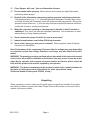
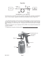
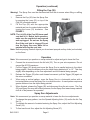
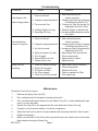
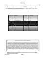
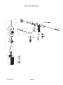
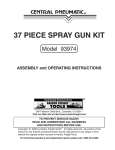
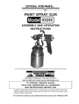
®
INDUSTRIAL PAINT SPRAY GUN
Model 91011
ASSEMBLY and OPERATING
INSTRUCTIONS
®
3491 Mission Oaks Blvd., Camarillo, CA 93011
Visit our Web site at http://www.harborfreight.com
Copyright © 2003 by Harbor Freight Tools® . All rights reserved. No portion of this
manual or any artwork contained herein may be reproduced in any shape or form
without the express written consent of Harbor Freight Tools.
For technical questions and replacement parts, please call 1-800-444-3353
Specifications
Operating and Maximum PSI
Air Consumption
Paint Capacity
Air Inlet
Nozzle Size
Feed Type
20 to 50 PSI/ 80 PSI Max.
4 CFM @ 30 PSI
1 Quart
1/4” - 18 NPS
.07”
Siphon
Save This Manual
You will need the manual for the safety warnings and precautions, assembly instructions,
operating and maintenance procedures, parts list and diagram. Keep your invoice with this
manual. Write the invoice number on the inside of the front cover. Keep the manual and
invoice in a safe and dry place for future reference.
Safety Warnings and Precautions
WARNING: When using tool, basic safety precautions should always be followed to
reduce the risk of personal injury and damage to equipment.
Read all instructions before using this tool!
1.
Keep work area clean. Cluttered areas invite injuries.
2.
Observe work area conditions. Do not use machines or power tools in damp or wet
locations. Don’t expose to rain. Keep work area well lit. Do not use air tools in the
presence of flammable gases or liquids.
3.
Keep children away. Children must never be allowed in the work area. Do not let
them handle machines, tools, extension cords, or air hoses.
4.
Store idle equipment. When not in use, tools must be stored in a dry location to
inhibit rust. Always lock up tools and keep out of reach of children.
5.
Use the right tool for the job. Do not attempt to force a small tool or attachment to
do the work of a larger industrial tool. There are certain applications forwhich this tool
was designed. It will do the job better and more safely at the rate for which it was
intended. Do not modify this tool and do not use this tool for a purpose for which it
was not intended.
6.
Dress properly. Do not wear loose clothing or jewelry as they can be caught in
moving parts. Protective, electrically non-conductive clothes and non-skid footwear
are recommended when working. Wear restrictive hair covering to contain long hair.
7.
Use eye and ear protection. Always wear ANSI approved impact safety goggles.
Wear an ANSI approved dust mask or respirator when working around chemical
dusts, paints and mists. Wear appropriate ear protection.
SKU 91011
Page 2
8.
Do not overreach. Keep proper footing and balance at all times. Do not reach over or
across running machines or air hoses.
9.
Maintain tools with care. Keep tools clean for better and safer performance. Follow
instructions for lubricating and changing accessories. Inspect tool cords and air hoses
periodically and, if damaged, have them repaired by an authorized technician. The
handles must be kept clean, dry, and free from oil and grease at all times.
10. Disconnect air supply. Disconnect air hose when not in use, when changing
accessories, and during maintenance.
11. Remove adjusting wrenches. Check that adjusting wrenches are removed from the
tool before attaching to the air source.
12. Avoid unintentional starting. Be sure the trigger is in the Off position when not in
use and before attaching to the air source. Do not carry any tool with your finger on
the trigger, whether it is attached to the air compressor or not.
13. Stay alert. Watch what you are doing, use common sense. Do not operate any tool
when you are tired.
14. Check for damaged parts. Before using any tool, any part that appears damaged
should be carefully checked to determine that it will operate properly and perform its
intended function. Check for alignment and binding of moving parts; any broken parts
or mounting fixtures; and any other condition that may affect proper operation. Any
part that is damaged should be properly repaired or replaced by a qualified technician.
Do not use the tool if any trigger does not operate properly.
15. Guard against electric shock. Prevent body contact with grounded surfaces such as
pipes, radiators, ranges, and refrigerator enclosures.
16. Replacement parts and accessories. When servicing, use only identical
replacement parts. Use of any other parts will void the warranty. Only use accessories
intended for use with this tool. Approved accessories are available from Harbor Freight
Tools.
17. Do not operate tool if under the influence of alcohol or drugs. Read warning
labels if taking prescription medicine to determine if your judgement or reflexes are
impaired while taking drugs. If there is any doubt, do not operate the tool.
18. Use proper size and type extension cord. If an extension cord is required, it must be
of the proper size and type to supply the correct current to the compressor without
heating up. Otherwise, the extension cord could melt and catch fire, or cause electrical
damage to the compressor. Check your compressor’s manual for the appropriate size
cord.
19. Maintenance. For your safety, maintenance should be performed regularly by a
qualified technician.
20. Compressed air only. Never use combustible gas as a power source.
21. Do not spray near open flames, pilot lights, stoves, heaters, or any other heat
source. Most solvents and coatings are highly flammable, particularly when sprayed.
SKU 91011
Page 3
22. Clean Sprayer with care. Use non-flammable solvents.
23. Do not smoke while spraying. Most solvents and coatings are highly flammable,
particularly when sprayed.
24. Read all of the information concerning coating products and cleaning solvents.
Chlorinated solvents (e.g. 1-1-1 Trichlorethylene and Methylene Chloride, also known
as methyl chloride) can chemically react with aluminum and may explode. Many paint
sprayers contain aluminum. If you have any doubt about potential chemical reactions,
contact the solvent or coating manufacturer.
25. Materials used when painting or cleaning may be harmful or fatal if inhaled or
swallowed. Only use in an area with adequate ventilation. Use a respirator or mask
when painting or using cleaning solvents.
26. Never release the sprayer lid while the cup is pressurized.
27. Industrial applications must follow OSHA requirements.
28. Never point a spray gun at a person or animal. Always properly mask all objects
that are not to be painted.
Note: Performance of the compressor (if powered by line voltage) may vary depending
on variations in local line voltage. Extension cord usage may also affect tool performance.
WARNING: The warnings, cautions, and instructions discussed in this instruction manual
cannot cover all possible conditions and situations that may occur. It must be understood by the operator that common sense and caution are factors which cannot be
built into this product, but must be supplied by the operator.
WARNING: The brass components of this product contain lead, a chemical known to
the State of California to cause birth defects (or other reproductive harm).
(California Health & Safety code 25249.5, et seq.)
Unpacking
When unpacking, check to make sure the parts listed on page 8 are included. If any parts
are missing or broken, please call Harbor Freight Tools at the number on the cover of this
manual as soon as possible.
SKU 91011
Page 4
Operation
1/4” NPS
Sprayer
For best service you should incorporate a regulator and inline filter, as shown in the diagram
above. Hoses, couplers, regulators, and filters are all available at Harbor Freight Tools.
1. You will need to prepare a 1/4” air connector (sold separately) to connect to the air inlet on
the Spray Gun. First, wrap the 1/4” air connector (not included) with pipe thread seal tape
before threading it into the Air Inlet (33). Connect the 3/8” ID Air Source Hose to the Spray
Gun.
2. Set the air pressure on your compressor to 20 to 50 PSI. Do not exceed the maximum air
pressure of 80 PSI.
3. Check the air connection for leaks and then disconnect the tool from the air source.
Spread Adjusting Valve (12)
Fluid Adjusting
Screw (19)
Trigger (20)
Air Inlet (33)
Air Adjusting
Screw (27)
Cup (26)
SKU 91011
Page 5
Operation (continued)
Filling the Cup (26)
Warning! The Spray Gun must be disconnected from the air source when filling or refilling
material.
1.
2.
Remove the Cup (26) from the Spray Gun
by pressing the Lever (23) on top of the
Cup (26) counterclockwise.
Fill the Cup (26) with the appropriate
material and turn it counterclockwise while
turning the Lever (23) clockwise. See
FIGURE 1.
FIGURE 1
NOTE: The Lid (43) of the Cup (26) has a small
vent hole in it. Before each operation,
make sure the vent hole is not covered
and unplugged. Do not use the Spray
Gun if the vent hole is clogged. Do not
turn the Spray Gun over while full or
material will clog the vent hole.
Note: Before spraying, mask all objects you do not want sprayed and lay cloths (not included)
on the floors.
Operation
Note: We recommend you practice on scrap material to adjust and get to know the Gun.
1.
2.
3.
4.
5.
Connect the air source hose to the Air Inlet (33). Turn on your air compressor. Do not
exceed the 80 PSI maximum.
Pull the Trigger (20) slowly and move the Spray Gun in parallel strokes to the object
being painted. Keep the distance from the object being painted at 4” to 12”. This may
slightly differ depending on the flow adjustment and the material being sprayed.
Release the Trigger (20) after each forward movement; pull the Trigger (20) again on
the return movement.
When using a vertical pattern, move the Spray Gun in a horizontal motion; with a
horizontal pattern move the Spray Gun in a vertical motion. A round pattern requires a
greater distance from the object being painted.
When finished, release the Trigger (20) and disconnect from the air source. The Cup
(26) and Spray Gun may still hold air pressure, fire the Spray Gun toward scrap material
until all of the pressure is expended.
Spray Gun Adjustments
Note: We recommend you practice on scrap material to learn the fine tune adjustments.
1.
2.
3.
To change the spray pattern, turn the Spread Adjusting Valve (12) and/or the Air Cap
Set (1).
To regulate the amount of material entering the Spray Gun, adjust the Fluid Adjusting
Screw (19).
To fine tune the air flow, adjust the Air Adjusting Screw (27).
SKU 91011
Page 6
Troubleshooting
PROBLEM
REMEDY
CAUSE
1. Add undiluted product
(check viscosity)
2.
Reduce
paint flow by tightening
Improper spray adjustment
Fluid Adjusting Screw (19)
3. Reduce air flow by turning Air
Too much air flow
Adjusting Screw (27) down
4. Release Trigger on back stroke
Holding Trigger too long
5. Increase distance between nozzle
Spraying too close
and object
1. Paint too diluted
Paint drips on the
2.
object being painted
3.
4.
5.
4.
5.
6.
7.
1. Add undiluted product
(check viscosity)
2.
Increase
paint flow by loosening
Improper spray adjustment
Fluid Adjusting Screw (19)
3. Increase air flow by loosening Air
Air flow too weak
Adjusting Screw (27)
4. Move Spray Gun more slowly
Spray movement too fast
5. Clean components
Gun clogged
6. Spray closer to object
Spray distance too far
7. Adjust Nozzle
Nozzle set too fine
1.
2.
3.
4.
5.
Paint not thinned enough
Spray Gun clogged
Air Hose is broken
Air Filter clogged
Paint Cup not fully closed
1. Paint too diluted
Paint Application
uneven or irregular
2.
3.
Spray Gun not
operating
1.
2.
3.
4.
5.
Add thinner (check viscosity)
Clean components
Replace Air Hose
Clean or replace Air Filter
Close paint cup
Maintenance
Disconnect from the air source.
1.
2.
3.
Remove the Spray Gun Cup (26).
Pour residual paint into the paint container and seal it.
Pour non-flammable paint thinner into the Plastic Cup (26). If water based paint was
used, you can use water.
4.
Secure the Cup (26) to the appropriate Gun and shake the liquid in the cup.
5.
Connect to the air source and turn on the air compressor.
6.
Spray the liquid onto a piece of scrap material until the spray material is free of paint.
7.
Repeat if necessary.
8.
Make sure that both of the Vent Holes (top and bottom) are totally clear of paint and
debris before storing the Spray Gun.
Page 7
SKU 91011
Parts List
Note: Certain parts cannot be ordered separately and must be ordered as part of an entire
set.
* (41) Air Valve Seat Set includes parts A, B, C, D, E, F, G on the diagram below.
* (39) Lid Assembly Set includes part numbers 25, 31, 44, 23, 43, 34, 22, 30, 29, 42
Part No.
1
2
9
10
11
12
13
15
16
17
18
19
20
22*
21
23*
Description
Air Cap Set
Nozzle
Needle Valve Spring
Copper Gasket
Fluid Needle
Spread Adj. Valve Set
Trigger Pin
0-ring
Needle Valve Guide
Screw
Fluid Joint
Fluid Adjusting Screw
Trigger
0-ring
Air Orienting Ring
Lever
Part No.
24
25*
26
27
29*
30*
31*
32
33
34*
38*
39*
41*
42*
43*
44*
Description
Air Hose Joint
Copper Pin
Cup
Air Adjusting Valve Set
Baffle
Nut
Screw
Filter
Air Inlet
Cup Gasket
Spare Parts
Lid Assy. Set
Air Valve Set
Material Tube Assembly
Cup Top Assemby
Yoke Assembly
PLEASE READ THE FOLLOWING CAREFULLY
THE MANUFACTURER AND/OR DISTRIBUTOR HAS PROVIDED THE PARTS DIAGRAM IN THIS
MANUAL AS A REFERENCE TOOL ONLY. NEITHER THE MANUFACTURER NOR DISTRIBUTOR MAKES ANY REPRESENTATION OR WARRANTY OF ANY KIND TO THE BUYER THAT
HE OR SHE IS QUALIFIED TO MAKE ANY REPAIRS TO THE PRODUCT OR THAT HE OR SHE
IS QUALIFIED TO REPLACE ANY PARTS OF THE PRODUCT. IN FACT, THE MANUFACTURER
AND/OR DISTRIBUTOR EXPRESSLY STATES THAT ALL REPAIRS AND PARTS REPLACEMENTS SHOULD BE UNDERTAKEN BY CERTIFIED AND LICENSED TECHNICIANS AND NOT
BY THE BUYER. THE BUYER ASSUMES ALL RISK AND LIABILITY ARISING OUT OF HIS OR
HER REPAIRS TO THE ORIGINAL PRODUCT OR REPLACEMENT PARTS THERETO, OR ARISING OUT OF HIS OR HER INSTALLATION OF REPLACEMENT PARTS THERETO.
NOTE: Some parts are listed and shown for illustration purposes only and are not available
individually as replacement parts.
SKU 91011
Page 8
Assembly Drawing
39
SKU 91011
Page 9