1
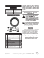
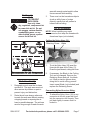
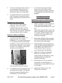
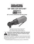
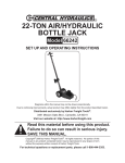
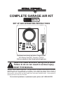
Complete Garage Air Kit
66747
Set up and Operating Instructions
Distributed exclusively by Harbor Freight Tools®.
3491 Mission Oaks Blvd., Camarillo, CA 93011
Visit our website at: http://www.harborfreight.com
Read this material before using this product.
Failure to do so can result in serious injury.
Save this manual.
Copyright© 2009 by Harbor Freight Tools®. All rights reserved. No portion of this manual or any artwork
contained herein may be reproduced in any shape or form without the express written consent of
Harbor Freight Tools. Diagrams within this manual may not be drawn proportionally. Due to continuing
improvements, actual product may differ slightly from the product described herein. Tools required for
assembly and service may not be included.
For technical questions or replacement parts, please call 1-800-444-3353.
Save This Manual
CAUTION, used
with the safety
alert symbol,
indicates a hazardous
situation which, if not
avoided, could result in minor
or moderate injury.
Keep this manual for the safety
warnings and precautions, assembly,
operating, inspection, maintenance and
cleaning procedures. Write the product’s
serial number in the back of the manual
near the assembly diagram (or month
and year of purchase if product has no
number). Keep this manual and the
receipt in a safe and dry place for future
reference.
NOTICE is used to
address practices
not related to
personal injury.
CAUTION, without
the safety alert
symbol, is used to
address practices not related
to personal injury.
Safety Alert Symbol
and Signal Words
In this manual, on the labeling,
and all other information
provided with this product:
This is the safety alert
symbol. It is used to alert
you to potential personal
injury hazards. Obey all
safety messages that
follow this symbol to avoid
possible injury or death.
IMPORTANT SAFETY
INSTRUCTIONS
Instructions Pertaining
to a Risk of Fire,
Electric Shock, or
Injury to Persons
DANGER indicates
a hazardous
situation which, if
not avoided, will result in
death or serious injury.
WARNING – When using tools, basic
precautions should always be
followed, including the following:
a.
WARNING
indicates a
hazardous
situation which, if not
avoided, could result in death
or serious injury.
General
Work area
a.
SKU 66747
To reduce the risks of electric
shock, fire, and injury to persons,
read all the instructions before
using the tool.
Keep the work area clean and well
lighted. Cluttered benches and dark
areas increase the risks of electric
shock, fire, and injury to persons.
For technical questions, please call 1-800-444-3353.
Page 2
b.
c.
Do not operate air compressor in
explosive atmospheres, such as in
the presence of flammable liquids,
gases, or dust. The air compressor
is able to create sparks resulting in
the ignition of the dust or fumes.
b.
Stay alert. Watch what you are
doing and use common sense
when operating the tool. Do not
use any tool while tired or under
the influence of drugs, alcohol, or
medication. A moment of inattention
while operating the tool increases the
risk of injury to persons.
Dress properly. Do not wear loose
clothing or jewelry. Contain long
hair. Keep hair, clothing, and
gloves away from moving parts.
Loose clothes, jewelry, or long hair
increases the risk of injury to persons
as a result of being caught in moving
parts.
c.
Avoid unintentional starting.
Be sure the switch is off before
connecting to the air supply. Do not
carry any tool with your finger on the
switch or connect the tool to the air
supply with the switch on.
d.
Do not overreach. Keep proper
footing and balance at all times.
Proper footing and balance
enables better control of the tool in
unexpected situations.
e.
f.
Keep bystanders, children, and
visitors away while operating any
tool. Distractions are able to result in
the loss of control of the tool.
Personal safety
a.
ranges and refrigerators. There is
an increased risk of electric shock if
your body is grounded.
Avoid body contact with grounded
surfaces such as pipes, radiators,
SKU 66747
Explore the work piece to avoid
contact with hidden wiring.
Thoroughly investigate the work
piece for possible hidden wiring
before installing air kit. Contact with
live wiring will shock the operator.
Tool use and care
a.
Use clamps or another practical
ways to secure and support the
work piece to a stable platform.
Holding the work by hand or against
the body is unstable and is able to
lead to loss of control.
b.
Do not force the tool. Use the
correct tool for the application. The
correct tool will do the job better and
safer at the rate for which the tool is
designed.
c.
Do not use any tool if the switch
does not turn the tool on or off.
Any tool that cannot be controlled
with the switch is dangerous and
must be repaired.
d.
Disconnect tools from the
air source before making
any adjustments, changing
accessories, or storing the tool.
Such preventive safety measures
reduce the risk of starting the tool
unintentionally. Turn off and detach
the air supply, safely discharge any
residual air pressure, and release the
throttle and/or turn the switch to its off
position before leaving the work area.
e.
Store tools when idle out of reach
of children and other untrained
For technical questions, please call 1-800-444-3353.
Page 3
persons. Any tool is dangerous in
the hands of untrained users.
f.
g.
h.
Maintain any tool with care. Keep
a cutting tool sharp and clean. A
properly maintained tool, with sharp
cutting edges reduces the risk of
binding and is easier to control.
Check for misalignment or binding
of moving parts, breakage of
parts, and any other condition
that affects the tool’s operation.
If damaged, have the tool serviced
before using. Many accidents are
caused by poorly maintained tools.
There is a risk of bursting if the tool is
damaged.
Use only accessories that are
identified by the manufacturer for
the specific tool model. Use of an
accessory not intended for use with
the specific tool model, increases the
risk of injury to persons.
Service
a.
Tool service must be performed
only by qualified repair personnel.
b.
When servicing a tool, use only
identical replacement parts. Use
only authorized parts.
Air source
a.
Never connect to an air
source that is capable of
exceeding 150 psi. Over
pressurizing the tool may
cause bursting, abnormal
operation, breakage of the tool or
serious injury to persons. Use only
clean, dry, regulated compressed air
at the rated pressure or within the
rated pressure range as marked on
SKU 66747
the tool. Always verify prior to using
the tool that the air source has been
adjusted to the rated air pressure or
within the rated air-pressure range.
b.
Never use oxygen, carbon dioxide,
combustible gases or any bottled
gas as an air source for the tool.
Such gases are capable of explosion
and serious injury to persons.
Save these
instructions.
Symbols and
Specific Safety
Instructions
Symbol Definitions
Symbol
no
Property or statement
No-load speed
.../min
Revolutions or reciprocation per
minute
PSI
Pounds per square inch of pressure
ft-lb
Foot-pounds of torque
BPM
Blows per minute
CFM
Cubic Feet per Minute flow
SCFM
Cubic Feet per Minute flow at
standard conditions
NPT
National pipe thread, tapered
NPS
National pipe thread, straight
WARNING marking concerning Risk
of Eye Injury. Wear ANSI-approved
eye protection.
Chart continued in next column.
For technical questions, please call 1-800-444-3353.
Page 4
Symbol Definitions
Symbol
Property or statement
WARNING marking concerning Risk
of Hearing Loss. Wear hearing
protection.
WARNING marking concerning Risk
of Respiratory Injury. Wear NIOSHapproved dust mask/respirator.
WARNING marking concerning Risk
of Explosion.
Specific Safety Instructions
1.
The warnings and precautions
discussed in this manual cannot
cover all possible conditions and
situations that may occur. It must
be understood by the operator that
common sense and caution are
factors which cannot be built into this
product, but must be supplied by the
operator.
2.
Only use with accessories rated to
handle the forces exerted by this tool
during operation. Other accessories
not designed for the forces generated
may break and forcefully launch
pieces.
3.
Attach all accessories properly to the
tool before connecting the air supply.
A loose accessory may detach or
break during operation.
4.
Obey the manual for the air
compressor used to power this kit.
5.
Install an in-line shutoff valve to allow
immediate control over the air supply
in an emergency, even if a hose is
ruptured.
Save these
instructions.
SKU 66747
For technical questions, please call 1-800-444-3353.
Page 5
Functional Description
Specifications
Maximum Air Pressure
150 PSI
Manifold Block Inlet
Manifold Block Outlet
3/8” NPT
3/8” NPT
Ball Valve
3/8” NPT
The Water Drain Valve can be opened or
closed to exhaust water from the Outlet
Blocks. Turn the handle 90° parallel to valve
to open, turn the handle 90° across to valve
to close.
Initial Air Kit Set Up/
Assembly
Components and Controls
Read the entire Important
Safety Information
section at the beginning of this
manual including all text under
subheadings therein before set
up or use of this product.
Note: For additional information regarding
the parts listed in the following pages,
refer to the Assembly Diagram near
the end of this manual.
Unpacking
Part
Accessory LIST
Description
Qty
1
Outlet Block
2
2
Straight Union (1/2” x 3/8” NPT)
6
3
Elbow Union (1/2”)
4
4
Ball Valve
2
5
Brass Nipple (1/4” NPT)
2
6
Brass 45° Elbow (1/4” NPT)
2
7
Brass Plug (3/8” NPT)
3
8
Compressor Manifold Block
1
9
Tee Fitting (1/2”)
2
10
Nylon Hose (100’ x 1/2”)
1
11
Cutting Tool (blade included)
1
When unpacking, check to make sure
that the item is intact and undamaged. If
any parts are missing or broken, please
call Harbor Freight Tools at the number
shown throughout the manual as soon as
possible.
• This air kit may be shipped with
protective plugs covering air inlets.
Remove all plugs before set up.
REV 09g
SKU 66747
For technical questions, please call 1-800-444-3353.
Page 6
area with enough extra length to allow
free movement while working.
Air Supply
To prevent
explosion:
Use only clean,
dry, regulated, compressed air
to power this air kit. Do not
use oxygen, carbon dioxide,
combustible gases, or any
other bottled gas as a power
source for this air kit.
3.
There must not be hazardous objects
(such as utility lines or foreign
objects) nearby that will present a
hazard while working.
Air Kit Assembly
NOTE: When installing any metal
connector, first wrap the threads with
thread seal tape (not included).
Cutting the Nylon Hose (10).
Retaining Screw
Blade
Outlet Block
Compressor
Manifold
Block
1.
To cut the Nylon Hose (10) insert the
Hose into the jaws of the Cutter (11).
Press the jaws closed, cutting the Hose.
2.
If necessary, the Blade in the Cutting
Tool can be changed. Remove the
Retaining Screw and pull the blade
out. Wear protective gloves when
doing this to avoid cutting yourself.
Insert a new Blade (not included) and
replace the Retaining Screw.
Operating an Air Tool
Work Area Set Up
1.
2.
Designate a work area that is clean
and well-lit. The work area must not
allow access by children or pets to
prevent injury and distraction.
Route the air hose along a safe route
to reach the work area without creating
a tripping hazard or exposing the air
hose to possible damage. The air hose
must be long enough to reach the work
SKU 66747
Connecting Nylon Hose to a fitting.
1.
To attach the Nylon Hose (10) to any
connector in this kit, press the Hose
into the connector until it seats. Then
pull back lightly to assure that it is
locked in.
For technical questions, please call 1-800-444-3353.
Page 7
2.
To remove the Nylon Hose (10) from
any compression fitting in this kit,
push in evenly on the release ring,
and pull the Hose out of the fitting.
3.
To reattach the Hose, trim the end of
the Hose above the previous crimp,
before attempting to reconnect to the
fitting.
Planning your air line layout.
1.
Plan your air line layout before
beginning. The air line can be
installed inside the wall or on the
surface of the wall. Plan where all
Tees, Elbows, connections, Manifolds
and work stations will be located.
3.
Installing the Air Kit
Prepare the Compressor Manifold Block
(8) to install near your compressor.
1.
Attach a “jumper” to your compressor
outlet, which will connect to the
Compressor Manifold Block (8). To do
this:
Cut a short length of Nylon Hose (10),
Attach a Straight Union connector (2)
to one end. Install a Straight Union
connector (2) to the outlet of your
compressor regulator.
2.
Next, install a Straight Union connector
(2) into the Compressor Manifold Block
(8). Insert the end of the jumper.
3.
Attach Straight Union connectors (2)
to the Compressor Manifold Block (8)
as needed for your planned layout.
Insert a Brass Plug (7) into any
unused openings in the Manifold.
4.
Attach the Compressor Manifold
Block (8) to your wall. Use #10
wood screws (not included) or other
suitable fasteners to attach the
manifold to the wall.
5.
Run Nylon Hose (10) as required.
Use clamps or other fittings (not
included) to securely attach the Hose
to your walls.
6.
Install Union Elbows (3) or Tee
Fittings (9) as required.
Surface or Hidden installation
1.
You can run the Nylon Hose (10)
behind dry wall for a “hidden”
installation, or you can surface mount
it. It is easiest to perform the hidden
installation in new construction before
the dry wall is installed. In an existing
structure, it is easiest to perform the
surface mount installation.
Hidden Mounting
(with drywall removed for clarity)
2.
For hidden mounting, the Nylon Hose
runs behind the drywall. The Straight
Union (2) enters the Manifold (8) or
Outlet Block (1) from the back.
SKU 66747
For surface mounting, the Nylon
Hose runs on the surface of the
drywall, and the opening in the back
of the Manifold and Outlet Block are
plugged.
For technical questions, please call 1-800-444-3353.
Page 8
Prepare Outlet Block (1)
1.
Attach Straight Union connector (2)
to each Outlet Block (1) as needed.
Install Water Drain Valve (4) in
bottom opening of Outlet Block. Insert
a Brass Plug (7) into any unused
openings in the Outlet Block.
2.
Optionally, attach a 1/4” NPT quick
release coupling (not included) to the
45° Elbow (6).
3.
Attach the end of the Nylon Hose to
the Straight Union (2).
4.
Install the Outlet Blocks as desired.
Use #10 wood screws (not included)
or other suitable fasteners to attach
the Outlet to the wall. Be sure the
Water Drain Valve (4) is on the
underside.
problems are found, do not use
air kit until repaired.
To prevent
serious injury
from
accidental operation:
Turn off the tool, detach the
air supply, safely discharge
any residual air pressure in
the tool, and release the
throttle and/or turn the switch
to its off position before
performing any inspection,
maintenance, or cleaning
procedures.
To prevent serious
injury:
Do not adjust or tamper with
any control or component in a
way not specifically explained
within this manual. Improper
adjustment can result in
tool failure or other serious
hazards.
Operating Instructions
Read the entire Important
Safety Information
section at the beginning of this
manual including all text under
subheadings therein before set
up or use of this product.
General Operating Instructions
1.
If an automatic oiler is not used, add
a few drops of Pneumatic Tool Oil to
the airline connection before using
any air tool. Add a few drops more
after each hour of continual use.
2.
Connect air hose (not included) to
the Outlet Block (1). Connect air tool
(not included) to the air hose. Use
the tool according to manufacturer’s
recommendations.
Inspect Air Kit before use,
looking for damaged, loose,
and missing parts. If any
SKU 66747
For technical questions, please call 1-800-444-3353.
Page 9
3.
4.
To prevent
serious injury
from
accidental operation:
Turn off any tool, detach the
air supply, safely discharge
any residual air pressure in
the tool, and release the
throttle and/or turn the switch
to its off position before
performing any inspection,
maintenance, or cleaning
procedures.
If the tool requires more force to
accomplish the task, verify that the
tool receives sufficient, unobstructed
airflow (CFM) and increase the
pressure (PSI) output of the regulator
up to the maximum air pressure
rating of this tool.
CAUTION! To prevent tool
and accessory failure,
resulting in injury:
Do not exceed the air kit’s
maximum air pressure rating.
If the tool still does not have sufficient
force at maximum pressure and
sufficient airflow, then a larger tool
may be required.
To prevent serious
injury from tool
failure:
Do not use damaged
equipment. If abnormal
noise, vibration, or leaking
air occurs, have the problem
corrected before further use.
When work is completed, turn off
the tool, detach the air supply, safely
discharge any residual air pressure in
the tool, and release the throttle and/
or turn the switch to its off position
after use. Clean external surfaces
of the tool with clean, dry cloth, and
apply a thin coat of tool oil. Then
store the tool indoors out of children’s
reach.
User-Maintenance Instructions
Cleaning, Maintenance,
and Lubrication
1.
Daily - Air Supply Maintenance:
Every day, perform maintenance
on the air supply according to
the compressor manufacturers’
instructions. The lubricator’s oil
level needs to be maintained and
the moisture filter must be regularly
drained. Performing routine
maintenance on the air supply will
allow air tools to operate more safely
and will also reduce wear on the tool.
3.
Drain water from the Water Drain
Valves (4) daily.
4.
Periodically check for air leaks.
Repair any leak before continuing to
work.
Procedures not specifically
explained in this manual
must be performed only by a
qualified technician.
SKU 66747
For technical questions, please call 1-800-444-3353.
Page 10
ASSEMBLY DIAGRAM
10
1
11
6
2
4
9
8
Part
#
5
7
Parts LIST
Description
3
Qt’y
1
Outlet Block
2
2
Straight Union (1/2” x 3/8” NPT)
6
3
Elbow Union (1/2”)
4
4
Ball Valve
2
5
Brass Nipple (1/4” NPT)
2
6
Brass 45° Elbow (1/4” NPT)
2
7
Brass Plug (3/8” NPT)
3
8
Compressor Manifold Block
1
9
Tee Fitting (1/2”)
2
10
Nylon Hose (100’ x 1/2”)
1
11
Cutting Tool (blade included)
1
REV 09g
SKU 66747
For technical questions, please call 1-800-444-3353.
Page 11
LIMITED 90 DAY WARRANTY
Harbor Freight Tools Co. makes every effort to assure that its products meet high
quality and durability standards, and warrants to the original purchaser that this product
is free from defects in materials and workmanship for the period of 90 days from the date
of purchase. This warranty does not apply to damage due directly or indirectly, to misuse,
abuse, negligence or accidents, repairs or alterations outside our facilities, criminal activity,
improper installation, normal wear and tear, or to lack of maintenance. We shall in no event
be liable for death, injuries to persons or property, or for incidental, contingent, special
or consequential damages arising from the use of our product. Some states do not allow
the exclusion or limitation of incidental or consequential damages, so the above limitation
of exclusion may not apply to you. This warranty is expressly in lieu of all
other warranties, express or implied, including the warranties of
merchantability and fitness.
To take advantage of this warranty, the product or part must be returned to us with
transportation charges prepaid. Proof of purchase date and an explanation of the complaint
must accompany the merchandise. If our inspection verifies the defect, we will either
repair or replace the product at our election or we may elect to refund the purchase price
if we cannot readily and quickly provide you with a replacement. We will return repaired
products at our expense, but if we determine there is no defect, or that the defect resulted
from causes not within the scope of our warranty, then you must bear the cost of returning
the product.
This warranty gives you specific legal rights and you may also have other rights which
vary from state to state.
3491 Mission Oaks Blvd. • PO Box 6009 • Camarillo, CA 93011 • (800) 444-3353
PLEASE READ THE FOLLOWING CAREFULLY
The manufacturer and/or distributor has provided the parts list and assembly
diagram in this manual as a reference tool only. Neither the manufacturer or
distributor makes any representation or warranty of any kind to the buyer that
he or she is qualified to make any repairs to the product, or that he or she is
qualified to replace any parts of the product. In fact, the manufacturer and/or
distributor expressly states that all repairs and parts replacements should be
undertaken by certified and licensed technicians, and not by the buyer. The buyer
assumes all risk and liability arising out of his or her repairs to the original
product or replacement parts thereto, or arising out of his or her installation
of replacement parts thereto.
Record Product’s Serial Number Here:
Note: If product has no serial number, record month and year of purchase instead.
Note: Some parts are listed and shown for illustration purposes only, and are not
available individually as replacement parts.
SKU 66747
For technical questions, please call 1-800-444-3353.
Page 12