1
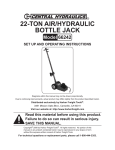
20 TON SHOP PRESS
WITH OIL FILTER CRUSHER
65330
Set up and Operating Instructions
Distributed exclusively by Harbor Freight Tools®.
3491 Mission Oaks Blvd., Camarillo, CA 93011
Visit our website at: http://www.harborfreight.com
Read this material before using this product.
Failure to do so can result in serious injury.
Save this manual.
Copyright© 2008 by Harbor Freight Tools®. All rights reserved. No portion of this manual or any artwork
contained herein may be reproduced in any shape or form without the express written consent of
Harbor Freight Tools. Diagrams within this manual may not be drawn proportionally. Due to continuing
improvements, actual product may differ slightly from the product described herein. Tools required for
assembly and service may not be included.
For technical questions or replacement parts, please call 1-800-444-3353.
Save This Manual
NOTICE is used to
address practices
not related to personal injury.
Keep this manual for the safety warnings and precautions, assembly, operating,
inspection, maintenance and cleaning procedures. Write the product’s serial number
in the back of the manual (or month and
year of purchase if product has no number). Keep this manual and the receipt in
a safe and dry place for future reference.
CAUTION, without
the safety alert
symbol, is used to address
practices not related to
personal injury.
IMPORTANT SAFETY
INSTRUCTIONS
Safety Alert Symbol and
Signal Words
In this manual, on the labeling,
and all other information provided with this product:
This is the safety alert
symbol. It is used to alert
you to potential personal
injury hazards. Obey all
safety messages that
follow this symbol to avoid
possible injury or death.
Instructions Pertaining to a
Risk of Injury to Persons
WARNING – When using shop equipment,
basic precautions should always be
followed, including the following:
Work area
a.
Do not install this Shop Press on any
asphalt or wood surface. Make sure
the Press is firmly secured to a dry,
oil/grease free, flat, level, concrete
surface capable of supporting the
weight of the Press, the workpiece
being pressed, and any additional
tools and equipment. Do not install
the Press on expansion seams or on
cracked, defective concrete.
b.
Keep the work area clean and well
lighted. Cluttered benches and dark
areas increase the risks of injury to
persons.
c.
Do not operate the Shop Press in explosive atmospheres, such as in the
presence of flammable liquids, gases,
or dust. The Press is able to create
sparks resulting in the ignition of the
dust or fumes.
DANGER indicates
a hazardous
situation which, if not
avoided, will result in death or
serious injury.
WARNING
indicates a
hazardous situation which, if
not avoided, could result in
death or serious injury.
CAUTION, used
with the safety
alert symbol, indicates a
hazardous situation which, if
not avoided, could result in
minor or moderate injury.
SKU 65330
For technical questions, please call 1-800-444-3353.
Page 2
d.
Keep bystanders, children, and visitors away while operating the Shop
Press. Distractions are able to result
in the loss of control of the tool.
g.
Never leave a compressed workpiece
unattended. Whenever a workpiece
is compressed, there is a very large
amount of force that has been stored
in the workpiece which must be controlled until the Press Head or Filter
Crushing Head is relaxed.
h.
Always release a load from the Shop
Press, and disconnect the unit from
its air supply source before performing any services or maintenance on
the unit.
i.
Stay alert. Watch what you are doing
and use common sense when operating the Shop Press. Do not use the
Press while tired or under the influence of drugs, alcohol, or medication.
A moment of inattention while operating the Press increases the risk of
injury to persons.
j.
Dress properly. Do not wear loose
clothing or jewelry. Contain long hair.
Keep hair, clothing, and gloves away
from moving parts. Loose clothes,
jewelry, or long hair increases the risk
of injury to persons as a result of being caught in moving parts.
Personal safety
a.
Never exceed the recommended 110
to 120 PSI working pressure and 20
ton pressing capacity for this Shop
Press. This Press will do the job better and safer at the PSI and pressing
capacity for which it was designed.
b.
Make sure to read and understand all
instructions and safety precautions as
outlined in the manufacturer’s service
manual for the workpiece you are
pressing. Always use the manufacturer’s recommended pressing points,
minimum/maximum pressing force
required, etc., for the workpiece you
are pressing.
c.
Prior to using the Shop Press, make
sure tool trays, stands, and all other
tools and equipment are removed
from the Working Bed.
d.
Always keep your hands and fingers
safety away from the Press Head
and Filter Crushing Head during the
pressing process.
k.
Never attempt to remove a workpiece
stuck in the moving parts of the Shop
Press while it is connected to its air
supply source.
Avoid unintentional starting. Be sure
the Lever on the Valve Body of the
Air/Hydraulic Jack is off before connecting to the air supply.
l.
Remove adjusting keys and wrenches before connecting to the air supply. A wrench or a key that is left
attached to a moving part of the Shop
Press increases the risk of personal
injury.
e.
f.
Once contact between the Press
Head or Filter Crushing Head and the
workpiece has been made, step away
as far as possible and continue to
slowly apply pressure until the procedure is completed.
SKU 65330
m. Do not overreach. Keep proper footing and balance at all times. Proper
footing and balance enables better
For technical questions, please call 1-800-444-3353.
Page 3
control of the tool in unexpected situations.
n.
Use safety equipment. A
dust mask, non-skid safety
shoes and a hard hat must
be used for the applicable
conditions. Wear heavy-duty work
gloves during use.
o.
Always wear eye protection. Wear ANSI-approved
safety goggles.
p.
Always wear hearing
protection when using the
Shop Press. Prolonged
exposure to high intensity
noise is able to cause hearing loss.
q.
WARNING! The brass components
of this product contain lead, a chemical known to the State of California
to cause birth defects (or other reproductive harm). California Health &
Safety Code 25249.5, et seq.)
c.
Use clamps or another practical way
to secure and support the workpiece
to Arbor Plates and Press Apron.
Holding the work by hand or against
the body is unstable and is able to
lead to loss of control.
d.
Do not force the Shop Press. Use the
correct equipment for the application.
The correct equipment will do the job
better and safer at the rate for which
the equipment is designed.
e.
Do not use the Shop Press if the Lever on the Valve Body of the Air/Hydraulic Jack does not turn the Press
on or off. Any equipment that cannot
be controlled is dangerous and must
be repaired.
f.
Disconnect the Shop Press from the
air source before making any adjustments, changing accessories, or storing the Press. Such preventive safety
measures reduce the risk of starting
the Press unintentionally. Turn off
and detach the air supply, safely discharge any residual air pressure, and
release the Lever on the Valve Body
of the Air/Hydraulic Jack before leaving the work area.
g.
Keep the Air/Hydraulic Jack properly
filled with hydraulic oil. For instructions, refer to the Air/Hydraulic Jack
owner’s manual (included).
h.
Keep the Shop Press out of reach of
children and other untrained persons.
A Shop Press is dangerous in the
hands of untrained users.
i.
Maintain the Shop Press with care. A
properly maintained Shop Press reduces the risk of binding and is easier
to control.
Tool use and care
a.
b.
WARNING! If you detect anything
that may indicate imminent structural
failure to the Shop Press, discontinue
using the Press immediately. Disconnect the Press from its air supply
source, and have the Press repaired
before further use.
Avoid off-center loads. If the Ram
seems unusually hard to press, immediately stop the operation. Disconnect the Shop Press from its
air supply source, and adjust the
workpiece to eliminate or diminish an
off-center load. Do not operate the
Press if the workpiece tilts or binds
during the down movement of the
Ram.
SKU 65330
For technical questions, please call 1-800-444-3353.
Page 4
j.
Check for misalignment or binding of
moving parts, breakage of parts, and
any other condition that affects the
Shop Press’ operation. If damaged,
have the Press serviced before using.
Many accidents are caused by poorly
maintained equipment. There is a risk
of bursting if the equipment is damaged.
k.
Use only accessories that are identified by the manufacturer for the
specific Shop Press model. Use of an
accessory not intended for use with
the specific model increases the risk
of injury to persons.
l.
Only use with accessories rated to
handle the forces exerted by this
Shop Press during operation. Other
accessories not designed for the
forces generated may break and
forcefully launch pieces.
m. Attach all accessories properly to the
Shop Press before connecting the
air supply. A loose accessory may
detach or break during operation.
n.
Install an in-line shutoff valve to allow
immediate control over the air supply
in an emergency, even if a hose is
ruptured.
Service
a.
b.
c.
Equipment service must be performed only by qualified repair personnel.
When servicing the Shop Press, use
only identical replacement parts. Use
only authorized parts.
Use only the lubricants supplied with
the Shop Press or specified by the
manufacturer.
SKU 65330
Air source
a.
Never connect to an air
source that is capable of
exceeding 120 PSI. Over
pressurizing the tool may
cause bursting, abnormal operation,
breakage of the tool or serious injury
to persons. Use only clean, dry,
regulated compressed air at the rated
pressure or within the rated pressure
range as marked on the tool. Always
verify prior to using the tool that the
air source has been adjusted to the
rated air pressure or within the rated
air-pressure range.
b.
Never use oxygen, carbon dioxide,
combustible gases or any bottled gas
as an air source for the tool. Such
gases are capable of explosion and
serious injury to persons.
Symbol DEFINITIONS
Symbol
no
Property or statement
No-load speed
.../min
Revolutions or reciprocation per
minute
PSI
Pounds per square inch of pressure
ft-lb
Foot-pounds of torque
BPM
Blows per minute
CFM
Cubic Feet per Minute flow
SCFM
Cubic Feet per Minute flow at
standard conditions
NPT
National pipe thread, tapered
NPS
National pipe thread, straight
Chart continued in next column.
For technical questions, please call 1-800-444-3353.
Page 5
Symbol
ASSEMBLY INSTRUCTIONS
Property or statement
WARNING marking concerning Risk
of Eye Injury. Wear ANSI-approved
eye protection.
Read the entire Important
Safety Information
section at the beginning of this
manual including all text under
subheadings therein before set
up or use of this product.
WARNING marking concerning Risk
of Hearing Loss. Wear hearing
protection.
WARNING marking concerning Risk
of Respiratory Injury. Wear NIOSHapproved dust mask/respirator.
WARNING marking concerning Risk
of Explosion.
Note: For additional information regarding
the parts listed in the following pages,
refer to the Assembly Diagram near
the end of this manual.
1.
Attach the two Legs (16) to the Working Bed (15) using four Bolts (17),
four Flat Washers (18), four Spring
Washers (19), and four Nuts (20).
(See Assy. Diagram.)
2.
Attach the two Uprights (12) to the
Working Bed (15) using four Bolts
(4), four Flat Washers (3), four Spring
Washers (2) and four Nuts (1). Hand
tighten only. (See Assy. Diagram.)
3.
Attach the two Screw Hooks (6) to the
Frame (7) using two Flat Washers (8)
and two Nuts (10). Leave the Nuts
untightened to provide easy Springs
attachment. (See Assy. Diagram.)
4.
Slide the Frame (7) down between
the two Uprights (12) onto the Working Bed (15). (See Assy. Diagram.)
Unpacking
5.
When unpacking, check to make sure
that the item is intact and undamaged. If
any parts are missing or broken, please
call Harbor Freight Tools at the number
shown throughout the manual as soon as
possible. Note: Two or more able bodied
people will be needed to set up this heavy
piece of equipment.
Attach the Top Cross Beam (22) to
the two Uprights (12) using four Bolts
(4), four Flat Washers (3), four Spring
Washers (2), and four Nuts (1).
(See Assy. Diagram.)
6.
Attach one end of the Springs (5) to
the mounting holes on the Top Cross
Beam (22) and the other end of the
Springs to the Screw Hooks (6) on
the Frame (7). (See Assy. Diagram.)
SAVE THESE INSTRUCTIONS
PRODUCT SPECIFICATIOns
Maximum Pressing Capacity
20 Tons (40,000 Pounds)
Air Pressure Range*
110 PSI to 120 Maximum PSI
Operating Methods
Air Operated and Manually Operated
Air Inlet Size
1/4” x 18 NPT
Ram Stroke
6-1/2”
Crusher Diameter
5-1/8” O.D.
Oil Filter Capacity
Up to 6” H x 4” Diameter
Press Head Diameter
4-1/2”
Distance Between Uprights
16-3/4”
Arbor Plate Dimensions
2-1/16” L x 7-1/4” W x 3/4” Thick
Mounting Hole Diameter
1/2” (Qty. 4)
*Exceeding maximum air pressure limit may cause
damage/injury.
SKU 65330
For technical questions, please call 1-800-444-3353.
Page 6
7.
With the help of another person,
elevate and position the Air/Hydraulic
Jack (21) to Top Cross Beam (22).
Tighten Set Screw (25) against Ram
top of the Jack. Raise Frame (7) and
tighten Nut (10) to secure the Jack
(21). (See Assy. Diagram.)
8.
Tighten all Nuts and Bolts.
9.
If you will use the unit as a common Press: Place the Press Plates
(26) on the Working Bed (15). Then
screw the Press Head (9) under the
Frame (7). (See Assy. Diagram.)
10. If you will use the unit as a filter
crusher: Screw the Filter Crushing Head (13) and Connecting Rod
(11) under the Frame (7). Attach
the Drain Hose (24) to the bottom
outlet of the Crushing Housing (14)
with one Clamp (23). Then place the
Crusher attachment on the Working
Bed (15). NOTE: Make sure the
Drain Hose empties into a proper oil
container. (See Assy. Diagram.)
Air Supply
To prevent
explosion:
Use only clean, dry, regulated,
compressed air to power this
tool. Do not use oxygen,
carbon dioxide, combustible
gases, or any other bottled
gas as a power source for this
tool.
11. Use a proper lifting device to move
the assembled Shop Press to the
desired work location.
12. Use the four 1/2” diameter mounting
holes in the Legs (16) as a template
for drilling four 1/2” diameter holes in
the concrete floor surface. Temporarily remove the Shop Press from its
work location. Then drill the four 1/2”
mounting holes in the concrete.
(See Assy. Diagram.)
13. Set the Shop Press back into position, and firmly secure the Shop
Press to the concrete floor surface
using appropriate concrete anchors
(not included).
14. The Shop Press is now ready to use.
SKU 65330
1.
Incorporate shut-off valve, regulator
with pressure gauge, and filter for
best service, as shown in the previ-
For technical questions, please call 1-800-444-3353.
Page 7
ous diagram. An in-line shutoff
valve is an important safety device
because it controls the air supply
should the air hose rupture.
allow it to build up pressure until it
cycles off.
7.
Adjust the air compressor’s output
regulator so that the air output is
enough to properly power the tool,
but the output will not exceed the
tool’s maximum air pressure (120
PSI) at any time. Adjust the pressure gradually, while checking the air
output gauge to set the right pressure
range.
8.
Inspect the air connections for leaks.
Repair any leaks found.
9.
If the Shop Press will not be used at
this time, release the Lever on the
Valve Body of the Air/Hydraulic Jack
to prevent accidental operation.
Note: If an automatic oiler system is not
used, add a few drops of Pneumatic
Tool Oil to the airline connection before operation. Add a few more drops
after each hour of continual use.
2.
Attach an air hose to the compressor’s air outlet. Connect the air hose
to the air inlet of the tool. Other components, such as a connector and
quick coupler, will make operation
more efficient, but are not required.
WARNING! To prevent serious
injury from accidental
operation:
Do not install a female quick
coupler on the tool. Such a coupler
contains an air valve that will allow
the air tool to retain pressure and
operate accidentally after the air
supply is disconnected.
Note: Air flow, and therefore tool performance, can be hindered by undersized air supply components.
3.
The air hose must be long enough
to reach the work area with enough
extra length to allow free movement
while working.
4.
Make sure the Lever on the Valve
Body of the Air/Hydraulic Jack is in
the off position. (Refer to the Air/Hydraulic Jack owner’s manual.)
5.
Close the in-line safety valve between the compressor and the Shop
Press.
6.
Turn on the air compressor according
to the manufacturer’s directions and
SKU 65330
For technical questions, please call 1-800-444-3353.
Page 8
Operating Instructions
Read the entire Important
Safety Information
section at the beginning of this
manual including all text under
subheadings therein before set
up or use of this Shop Press.
Inspect tool before use, looking
for damaged, loose, and
missing parts. If any problems
are found, do not use the Shop
Press until repaired.
1.
2.
If the Shop Press requires more force
to accomplish the task, verify that the
unit receives sufficient, unobstructed
airflow (CFM) and increase the
pressure (PSI) output of the regulator
up to the maximum air pressure
rating (120 PSI) of this Press.
CAUTION! Do not exceed the
maximum air pressure rating. If the
tool still does not have sufficient force
at maximum pressure and sufficient
airflow, then a larger Shop Press may
be required.
If you will use the unit as a filter
crusher:
a.Place the Crushing Housing (14) in
the middle of the Working Bed (15).
(See Assy. Diagram.)
b.Screw the Filter Crushing Head (13)
firmly onto the Connecting Rod (11).
(See Assy. Diagram.)
c. Close the Release Valve on the Air/
Hydraulic Jack. Then insert the end
of the Jack Handle into the Handle
Bracket of the Jack and pump the
Jack Handle up and down. This
action will manually lower the Filter
Crushing Head (13). (See Air/Hydraulic Jack Owner’s Manual.)
SKU 65330
d.Lower the Filter Crushing Head (13),
making sure the Crushing Head can
be lowered into the Crushing Housing (14). (See Assy. Diagram.)
e.Raise the Crushing Head (13) all
the way up by opening the Release
Valve on the Air/Hydraulic Jack.
Then place the oil filter that is to be
crushed into the Crushing Housing
(14). (See Assy. Diagram.)
f. Close the Release Valve on the
Air/Hydraulic Jack. Use the Jack
Handle of the Air/Hydraulic Jack to
manually lower the Filter Crushing
Head (13) onto the oil filter until the
filter is crushed to within 25% of its
original height. (See Air/Hydraulic
Jack Owner’s Manual.)
g.Open the Release Valve on the Air/
Hydraulic Jack. This will allow the
Springs (5) to again raise the Crushing Head (13) so you can remove
the crushed oil filter. (See Assy.
Diagram and Air/Hydraulic Jack
Owner’s Manual.)
h.For pneumatic operation, Place the
Crushing Housing (14) in the middle
of the Working Bed (15)
(See Assy. Diagram.)
i. Screw the Filter Crushing Head (13)
firmly onto the Connecting Rod (11).
(See Assy. Diagram.)
j. Close the Release Valve on the Air/
Hydraulic Jack. (See Air/Hydraulic
Jack Owner’s Manual.)
k. Connect the air supply source to
the Air Valve Assembly of the Air/
Hydraulic Jack. Then set the compressor’s regulator between 110 and
120 PSI.
For technical questions, please call 1-800-444-3353.
Page 9
l. Close the Release Valve on the Air/
Hydraulic Jack. (See Air/Hydraulic
Jack Owner’s Manual.)
3.
a.To operate the Shop Press as a
general Press, remove the Crushing
Housing (14) and Crushing Head
(13) from the unit. If necessary, the
Connecting Rod (11) may be removed and the Press Head (9) can
be screwed under the Frame (7)
directly. Follow previous instructions
for the manual and pneumatic operation of the Shop Press.
(See Assy. Diagram.)
m.Then squeeze and hold the Lever of
the Air/Hydraulic Jack. This action
will pneumatically lower the Filter
Crushing Head (13). (See Assy.
Diagram and Air/Hydraulic Jack
Owner’s Manual.)
n.Slowly lower the Filter Crushing
Head (13), making sure the Crushing Head can be lowered into the
Crushing Housing (14).
(See Assy. Diagram.)
o.Raise the Crushing Head (13) all
the way up by opening the Release
Valve on the Air/Hydraulic Jack.
Then place the oil filter that is to be
crushed into the Crushing Housing
(14). (See Assy. Diagram and Air/
Hydraulic Jack Owner’s Manual.)
If you will use the unit as a general
Shop Press:
4.
To prevent accidents, turn off the
tool, detach the air supply and safely
discharge any residual air pressure in
the Shop Press.
p.Close the Release Valve on the Air/
Hydraulic Jack. (See Air/Hydraulic
Jack Owner’s Manual.)
q.Then squeeze and hold the Lever
of the Air/Hydraulic Jack to lower
the Filter Crushing Head (13). (See
Assy. Diagram and Air/Hydraulic
Jack Owner’s Manual.)
r. Continue lowering the Filter Crushing Head (13) onto the oil filter until
the filter is crushed to within 25% of
its original height.
(See Assy. Diagram.)
s. Open the Release Valve on the Air/
Hydraulic Jack. This will allow the
Springs (5) to again raise the Crushing Head (13) so you can remove
the crushed oil filter. (See Assy.
Diagram and Air/Hydraulic Jack
Owner’s Manual.)
SKU 65330
For technical questions, please call 1-800-444-3353.
Page 10
Maintenance
Instructions
The lubricator’s oil level needs to be
maintained and the moisture filter
must be regularly drained. Performing routine maintenance on the air
supply will allow the Shop Press to
operate more safely and will also
reduce wear on the Press.
Procedures not specifically
explained in this manual
must be performed only by a
qualified technician.
To prevent
serious injury
from accidental
operation:
Detach the air supply from the
Shop Press, and safely
discharge any residual air
pressure in the Press before
performing any inspection,
maintenance, or cleaning
procedures.
To prevent serious
injury from tool
failure:
Do not use damaged
equipment. If abnormal
noise, vibration, or leaking
air occurs, have the problem
corrected before further use.
3.
Periodically, or when the Air/Hydraulic
Jack does not work, or does not operate at its optimum capability: Check
the hydraulic oil level in the Jack assembly as well as purge the system.
Refer to the Jack assembly owner’s
manual (included) for filling (topping
off) the Jack assembly.
4.
To clean: Use a clean, damp cloth
and mild detergent or solvent to clean
the external parts of the Shop Press.
Do not immerse any part in liquid.
5. All maintenance,
service, and repairs not mentioned in
this manual must only be performed
by a qualified service technician.
Note: Note: These procedures are in
addition to the regular checks and
maintenance explained as part of the
regular operation of the manual and
air-operated Shop Press.
1.
Daily: Before each use, inspect the
general condition of the Shop Press
and its accessories. Check for bent,
cracked, or broken parts, damaged
hoses, and any other condition that
may affect its safe operation.
2.
Daily: Every day, perform maintenance on the air supply components
(air compressor, regulator, oiler, filter,
hoses, etc.) according to the component manufacturers’ instructions.
SKU 65330
For technical questions, please call 1-800-444-3353.
Page 11
Troubleshooting
Problem
Possible Causes
Shop Press does
not work, or
does not operate
at its optimum
capability.
1. Pressure Release Valve open.
2. Air compressor’s Regulator
not set at between 110 PSI
and maximum 120 PSI.
3. Loose and/or damaged Hose
connections.
4. Hydraulic oil level low.
5. Trapped air in the system
Damaged
workpiece.
Possible Solutions
1. Close Valve.
2. Set Regulator between 110 PSI and 120
maximum PSI.
3. Inspect all Hose connections.
4. Refill (top off) Pump Assembly with Hydraulic
oil.
5. Purge air (see Jack’s manual).
1. Workpiece not evenly
1. Place the workpiece evenly centered on the
centered on Arbor Plates.
Arbor Plates.
2. Workpiece not secured to
2. Use clamps to secure workpiece.
Arbor Plates and Press Apron.
Follow all safety precautions whenever diagnosing or servicing the
tool. Disconnect air supply before service.
PARTS LIST
Part #
1
2
3
4
5
6
7
8
9
10
11
12
13
SKU 65330
Description
Nut
Spring Washer
Flat Washer
Bolt
Spring
Screw Hook
Frame
Flat Washer
Press Head
Nut
Connecting Rod
Upright
Filter Crushing Head
Qty. Part #
16
14
16
15
16
16
16
17
2
18
2
19
1
20
2
21
1
22
2
23
1
24
2
25
1
26
Description
Crushing Housing
Working Bed
Leg
Bolt
Flat Washer
Spring Washer
Nut
Air/Hydraulic Jack
Top Cross Beam
Clamp
Drain Hose
Set Screw
Press Plate
For technical questions, please call 1-800-444-3353.
Qty.
1
1
2
4
4
4
4
1
1
1
1
3
2
Page 12
ASSEMBLY DIAGRAM
SKU 65330
For technical questions, please call 1-800-444-3353.
Page 13
LIMITED 90 DAY WARRANTY
Harbor Freight Tools Co. makes every effort to assure that its products meet high
quality and durability standards, and warrants to the original purchaser that this product is free from defects in materials and workmanship for the period of 90 days from
the date of purchase. This warranty does not apply to damage due directly or indirectly,
to misuse, abuse, negligence or accidents, repairs or alterations outside our facilities,
criminal activity, improper installation, normal wear and tear, or to lack of maintenance.
We shall in no event be liable for death, injuries to persons or property, or for incidental,
contingent, special or consequential damages arising from the use of our product. Some
states do not allow the exclusion or limitation of incidental or consequential damages, so
the above limitation of exclusion may not apply to you. This warranty is expressly in lieu of all other warranties, express or implied, including the
warranties of merchantability and fitness.
To take advantage of this warranty, the product or part must be returned to us with
transportation charges prepaid. Proof of purchase date and an explanation of the complaint must accompany the merchandise. If our inspection verifies the defect, we will either repair or replace the product at our election or we may elect to refund the purchase
price if we cannot readily and quickly provide you with a replacement. We will return repaired products at our expense, but if we determine there is no defect, or that the defect
resulted from causes not within the scope of our warranty, then you must bear the cost
of returning the product.
This warranty gives you specific legal rights and you may also have other rights
which vary from state to state.
3491 Mission Oaks Blvd. • PO Box 6009 • Camarillo, CA 93011 • (800) 444-3353
PLEASE READ THE FOLLOWING CAREFULLY
The manufacturer and/or distributor has provided the parts list and assembly
diagram in this manual as a reference tool only. Neither the manufacturer or
distributor makes any representation or warranty of any kind to the buyer that
he or she is qualified to make any repairs to the product, or that he or she is
qualified to replace any parts of the product. In fact, the manufacturer and/or
distributor expressly states that all repairs and parts replacements should
be undertaken by certified and licensed technicians, and not by the buyer. The
buyer assumes all risk and liability arising out of his or her repairs to the
original product or replacement parts thereto, or arising out of his or her
installation of replacement parts thereto.
Record Product’s Serial Number Here:
Note: If product has no serial number, record month and year of purchase instead.
Note: Some parts are listed and shown for illustration purposes only, and are not available individually as replacement parts.
SKU 65330
For technical questions, please call 1-800-444-3353.
Page 14