1
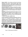
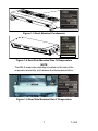
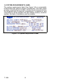
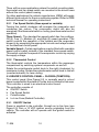
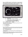
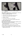
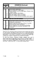
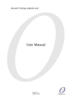
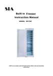
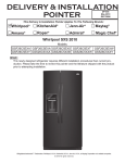
Transport Air Conditioning
R
TRANSPORT AIR CONDITIONING
OPERATOR’S MANUAL
for
SPLIT SYSTEM
Bus Air Conditioning Units
T--326 Rev --
OPERATOR’S
MANUAL
BUS AIR CONDITIONING
UNITS
GEN IV & GEN V
CONTENTS
Page
Introduction . . . . . . . . . . . . . . . . . . . . . . . . . . . . 1
Safety . . . . . . . . . . . . . . . . . . . . . . . . . . . . . . . . . . 3
Unit/System Information . . . . . . . . . . . . . . . . . 4
1.1
WHAT IS AIR CONDITIONING . . . . . . . . . . . . .
4
1.2
SPLIT SYSTEM . . . . . . . . . . . . . . . . . . . . . . . . . .
4
1.3
SYSTEM DESIGNATIONS . . . . . . . . . . . . . . . .
4
1.4
SYSTEM COMPONENTS . . . . . . . . . . . . . . . . .
4
1.5
MODEL AND SERIAL NUMBER TAGS . . . . . .
6
1.6
SYSTEM REQUIREMENTS LABEL . . . . . . . .
8
Unit Operation . . . . . . . . . . . . . . . . . . . . . . . . . .
9
2.1
OPERATING INSTRUCTIONS . . . . . . . . . . . . .
9
2.2
DRIVER’S CONTROL PANEL -- STANDARD .
9
2.3
DRIVER’S CONTROL PANEL -- FLORIDA . . .
10
2.4
PRE--TRIP INSPECTION . . . . . . . . . . . . . . . . . .
12
System Maintenance . . . . . . . . . . . . . . . . . . . . 13
3.1
Maintenance Schedule . . . . . . . . . . . . . . . . . . . .
13
3.2
Warranty/Service . . . . . . . . . . . . . . . . . . . . . . . . .
14
Index . . . . . . . . . . . . . . . . . . . . . . . . . . . . . . . Index 1
i
INTRODUCTION
SPLIT SYSTEM OPERATOR’S MANUAL
This guide has been prepared for the operator of Carrier Transport
Air Conditioning systems. It contains basic instructions for the daily
operation of the air conditioning system as well as safety
information, and other information that will help you to maintain a
comfort level for your self and your passengers. Please take the
time to read the information contained in this booklet and refer to
it whenever you have a question about the operation of your Carrier
Transport Air Conditioning system.
More comprehensive information can be found in the Split System
Operation and Service Manual (T--299). This manual can be
obtained from your Carrier Transport A/C dealer.
Your air conditioning system has been engineered to provide long,
trouble-free performance when it is properly operated and
maintained. A comprehensive maintenance program will help to
insure that the unit continues to operate reliably. Such a
maintenance program will also help to control operating costs,
increase the unit’s working life, and improve performance.
Some Vehicles may require information from manuals supplied by
the vehicle manufacturer or other special equipment suppliers. We
urge you to review all these publications carefully. This will help you
enjoy safe and trouble--free operation of your vehicle.
When having your unit serviced, be sure to specify genuine Carrier
Transicold replacement parts for the highest quality and best
reliability.
Carrier Transport Air Conditioning Dealers know your vehicle air
conditioning system best and will ensure your complete
satisfaction. To find the Dealer nearest you, go to
www.transportaircon.carrier.com and click on “Dealer Locator”, or
refer to the Carrier Bus Stop Dealer Directory (62--10810) or
contact the Carrier Transport Air Conditioning Technical Service
Hot--Line 1 (800) 450--2211.
At Carrier Transport Air Conditioning, we are continually working to
improve the products that we build for our customers. As a result,
specifications may change without notice.
1
SAFETY
Your Carrier Transport Air Conditioning system has been designed
with the safety of the operator in mind. During normal operation, all
moving parts are fully enclosed to help prevent injury. During all
pre-trip
inspections,
daily
inspections,
and
problem
troubleshooting, you may be exposed to moving parts; please stay
clear of all moving parts when the unit is in operation.
WARNING
Beware of unannounced starting of the unit. The unit
may cycle the fans and operating compressor unexpectedly as control requirements dictate. Turn system
off and disconnect battery power.
REFRIGERANT
The refrigerant contained in the air conditioning system can cause
frostbite, severe burns, or blindness when in direct contact with the
skin or eyes. For this reason, and because of legislation regarding
the handling of refrigerants during system service, we recommend
that, whenever your unit requires service of the refrigeration
system, you contact your nearest Carrier Transport Air
Conditioning authorized dealer for service.
3
T--326
UNIT/SYSTEM INFORMATION
1.1 WHAT IS AIR CONDITIONING
Air Conditioning is the cooling, heating, dehumidification, and
filtration of the air within the passenger compartment of a vehicle.
1.2 SPLIT SYSTEM
A Split System normally includes an Evaporator(s), a Condenser(s)
a Compressor(s) and interconnecting refrigerant hoses, fittings,
and electrical harnesses and controls. A listing of the system
components, along with specific data for each, is provided in
Paragraph 1.4.
1.3 SYSTEM DESIGNATIONS
Tie--In System -- Is a Carrier evaporator and condenser connected
to an existing OEM compressor and dash evaporator. The OEM
radiator type condenser is normally removed.
Max System -- A Carrier system installed along with an existing
OEM system. The systems operate independent of each other.
Stand--Alone (Standard) System -- All Carrier components
installed on a vehicle. These can be either single or dual
compressor systems.
1.4 SYSTEM COMPONENTS (Refer To Figure 1-1)
Return Air Thermostat/Sensor -- The system may be supplied
with a thermostat or thermistor. Both of these devices are
temperature sensitive components which when activated, signals
the Electro--Magnetic Clutch to engage/disengage. The return air
thermostat is normally located in the drivers control panel while the
return air thermistor is normally located in the return air flow of the
evaporator assembly.
Electro--Magnetic Clutch -- The Electro--Magnetic clutch controls
the operation of the compressor. When engaged, the compressor
circulates refrigerant and provides cooling.
Compressor -- The compressor is a belt driven, high--pressure
pump, which circulates the refrigerant through the evaporator and
condenser . The operation of the compressor is controlled by the
Electro--Magnetic clutch.
Condenser -- The condenser is normally located in the skirt or on
the roof of the vehicle. Its primary function is to reject heat, which
was transferred to the refrigerant by the evaporator from the
passenger compartment of the vehicle.
T--326
4
9
8
7
Air Out
Air In
6
3
5
4
2
10
Air In
Air Out
1
1.
2.
3.
4.
5.
Compressor
Electro--Magnetic Clutch
Discharge Line
Condenser
Filter Dryer/Sight Glass
Assembly
6.
7.
8.
9.
Liquid Line
Evaporator
Block Valve (TXV)
Freezestat--(Coil
freeze--up thermostat)
10. Suction Line
Figure 1-1 Component Locations
Filter/Dryer -- The filter/dryer removes moisture and particulate
matter from the refrigerant.
Expansion/Block Valve -- Meters the refrigerant flow into the
evaporator coil. The majority of the Gen 4 (Excel) and all Gen 5
systems use a nonadjustable block valve with an 8° F superheat
setting, which is preset at the factory. If you feel there is a problem
with the block valve, do not attempt to adjust the valve, if needed,
it should be replaced by an authorized Carrier Transport A/C
service center.
Evaporator -- The evaporator is located in the interior of the
vehicle. Its primary function is to transfer heat contained in the
passenger compartment air, into the refrigerant, which is circulated
by the compressor, through the evaporator coil. During this process
the air is also filtered and dehumidified.
Resistor -- Resistors are used to control the speeds of the
permanent magnet evaporator blower motors.
5
T--326
Pressure Switch -- The systems use high and low pressure
switches wired in series to control the power circuit of the
compressor clutch relay. If either pressure switch opens,
interrupting the circuit to the clutch relay, the operation of the
compressor will stop. When conditions return to normal the switch
will automatically reset and the compressor will resume operating.
The switches are non--adjustable.
Freeze--Up Thermostat -- Freeze--up thermostats are used to
prevent ice formation on the evaporator coil, which is an indication
that liquid refrigerat is getting back to the compressor. Carrier
Transport Air Conditioning systems use a freeze thermostat
(freezestat) wired in series with the system pressure switches and
thermostat/thermistor to control the operation of the compressor
clutch.
Refrigerant -- A refrigerant is a material that is used to move heat
from the passenger compartment to the outside air. It is a
substance that gives up heat by condensing at high temperature
and pressures and absorbs heat by evaporating at low
temperatures and pressures. The heat transfer properties
exhibited when refrigerant changes state is the foundation of the
refrigerant cycle.
1.5 MODEL AND SERIAL NUMBER TAGS
In order to identify the air conditioning components you have, you
will need to know the model number and serial number. All Carrier
Transport Air Conditioning evaporators, condensers and
compressors have a model/serial number tag located on the
assembly. See Figure 1-2 for skirt mounted condenser data tag
location, Figure 1-3 for the CM--7/11 rooftop condensers data tag
location, Figure 1-4 for GEN 4 (Excel) evaporator data tag location
and Figure 1-5 for GEN 5 evaporator data tag location. Knowing
these locations and the information on the data tags will aid you in
identifying the correct service procedures.
Figure 1-2 Skirt Mounted Condensers
T--326
6
Figure 1-3 Roof Mounted Condensers
EM--9 Location
Figure 1-4 Rear/Side Mounted Gen IV Evaporators
NOTE
The EM--9 evaporator data tag is located on the side of the
evaporator assembly, not between the blower assemblies.
Figure 1-5 Rear/Side Mounted Gen V Evaporators
7
T--326
1.6 SYSTEM REQUIREMENTS LABEL
The system requirements label (See Figure 1-6) is conveniently
located within the vehicle’s engine compartment. This label, when
properly completed by the installer, will give the servicing technician
the refrigerant and oil charge(s), evaporator(s), condenser(s), and
compressor(s) serial numbers, the drive belt(s) number, mount kit
number, the date of installation and the installer.
Figure 1-6 System Requirement Label
T--326
8
UNIT OPERATION
2.1 OPERATING INSTRUCTIONS
Before attempting to operate the system, power must be available
from the vehicle battery. If the engine is not running, start the
engine. Most systems will not operate unless a signal is received
to the controller from the vehicle ignition.
Carrier Transport Air Conditioning system’s can be supplied with
two different type manual controls. the Standard Manual Control
and the Florida Control
4
3
2
1
5
1 Control Panel Housing
2 Nameplate (Switch
Mounting)
3 Thermostat Control
4 Fan Speed Switch
(3 Speed or Variable)
5 Ambient Air Sensor
(Thermostat)
Figure 2-1 Drivers Control Panel -- Standard
2.2 DRIVER’S CONTROL PANEL -- STANDARD
The standard Drivers Control Panel (See Figure 2-1), consists of
an evaporator fan speed switch (three speed or variable) and an
adjustable thermostat. The drivers control panel is normally located
within easy reach of the driver. On larger bus applications there
could be two separate air conditioning system driver control panels.
One for each system.
9
T--326
There will be some applications where the switch mounting plate,
thermostat and fan speed switch are mounted in the drivers area
without the control panel housing.
On other applications the vehicle manufacturer (OEM) will supply
different type controls for the air conditioning system. Refer to OEM
technical manual for operating instructions.
2.2.1 Fan Speed Switch (three speed or variable)
Turning this switch clockwise will energize the evaporator and
condenser fan motors. The compressor clutch will also be
energized if the thermostat calls for cooling (see thermostat control
operation).
Three Speed -- The standard fan speed switch has four settings,
Off (0), Low (1), Medium (2), and High (3) speed operation. This
switch controls the operation of the system and the evaporator
blower(s) by energizing the appropriate circuits and relays located
on the electrical control panel.
Variable Speed -- Certain applications may be fitted with a variable
speed control switch instead of the standard three speed switch.
This switch controls the speed of the evaporator motors by varying
the supply voltage.
2.2.2 Thermostat Control
The thermostat controls the temperature within the passenger
compartment by switching system components on and off.
Rotate the potentiometer switch knob to the right (clockwise) for
maximum cooling. Rotate the potentiometer switch knob to the left
(counterclockwise) for less cooling.
2.3 DRIVER’S CONTROL PANEL -- FLORIDA (TEMPCON)
This control panel (See Figure 2-2) is normally used in school
buses located within the state of Florida, but not limited to that area.
This controller is wired to an electrical control board.
The controller consists of:
a. ON/OFF Switch
b. Fan Speed Switch
c. Potentiometer
d. In--Line Fuse (Behind Controller)
2.3.1 ON/OFF Switch
Power is supplied to the controller, through an in--line fuse (see
Figure 2-3) from a 12 VDC ignition source originating from the
vehicle. The controller will not operate until the ignition switch is
activated.
T--326
10
Move the ON/OFF switch to the ON position. A green light will
illuminate indicating that the controller has power. At the same time
the evaporator fans will operate in either Low, Medium or High
speed, depending on the Fan Speed switch location.
1
2
3
4
5
1
2
3
4
5
Face Plate
Green Light
Rocker Switch, 2 Position, ON/OFF
Rocker Switch, 3 Position, LOW--MED--HIGH
Thermostat Control (Potentiometer)
Figure 2-2 Switch Assembly (TEMPCON)
2.3.2 Fan Speed Switch -- 3 Speed
The evaporator fan speeds can be adjusted by pushing the rocker
switch to the desired position:
a. H = High Speed
b. M = Medium Speed
c. L = Low Speed
When the evaporator fan speed switch is positioned at the desired
speed, a signal is sent to the corresponding fan speed relay located
on the electrical circuit board.
2.3.3 Thermostat Control
The thermostat control potentiometer has an operating range of 60
to 85 degrees F.
Rotate the potentiometer switch knob to the right (clockwise) for
maximum cooling. Rotate the potentiometer switch knob to the left
(counterclockwise) for less cooling.
11
T--326
In--Line
Fuse &
Holder
Fuse
3 Amp
Fuse
Cover
Figure 2-3 In--Line Fuse & Holder (3 Amp)
2.3.4 In--line Fuse
The controller is protected by a 3 Amp ATO type in--line fuse
(Figure 2-3). To replace the fuse do the following:
a. Make sure ignition power is off.
b. Grasp fuse cover at finger grips and lift off cover.
c.
Remove fuse and check if fuse is defective.
d. Replace if needed.
e. Push fuse cover back on to in--line holder.
f.
Restore ignition power and place ON/OFF switch to ON.
2.4 PRE--TRIP INSPECTION
After starting system operation, allow system to stabilize for ten to
fifteen minutes and check for the following:
1. Listen for abnormal noises from the vehicle engine, evaporator
and condenser areas.
2. Ensure evaporator and condenser fans are operating.
3. Ensure water is not dripping from the evaporator or air ducts.
4. Check for reduced airflow. This is normally caused by dirty or
clogged evaporator filters.
T--326
12
SYSTEM MAINTENANCE
3.1 MAINTENANCE SCHEDULE
SYSTEM
ON
OPERATION
OFF
a. Daily Maintenance
X
X
X
Pre--trip inspection -- after starting. (Refer to paragraph 2.4)
Check tension and condition of drive belts.
b. Weekly Maintenance
X
X
Perform daily inspection
Check condenser, evaporator coils and return air
filters for cleanliness
c. Monthly Maintenance
X
X
X
X
X
X
Perform weekly inspection
Clean or replace Evaporator return air filters
Inspect Condenser coil fins -- Clean when necessary
Inspect refrigerant hoses and fitting connections.
Inspect electrical harness and connections
Check battery voltage -- System operates efficiently
at 13.5 volts
d. Quarterly Inspection
X
X
X
X
X
X
Inspect Evaporator(s) coil fins (heater coil if
installed) Clean if needed.
Check blower operation.
Check current draw and voltage of system components including fan motors.
Check that all compressor mounting brackets and
hardware are tight. Tighten and torque to proper
specifications.
Check hose and harness under vehicle for proper
support and protection
Check Evaporator drain lines.
13
T--326
SYSTEM
ON
OFF
OPERATION (Continued)
e. Semi--Annual Inspection and Maintenance
X
X
X
X
X
X
X
Check system pressures.
Check refrigerant in sight glass.
Check element in the the sight glass. (Green is dry
-- Yellow is wet)
Inspect condenser fan blades.
Open bus heater valves (In winter).
Close bus heater valves (In spring).
Remove or install optional condenser winter guard
kit.
f. Annual Inspection and Maintenance
X
X
X
X
X
Inspect electrical panel and terminals. Clean if
needed with a high-grade cleaner specifically formulated for this purpose.
Inspect Evaporator drain pan. (Clean if needed)
Check pressure switch operation.
Check evaporator roof mounting and sealing.
Check condenser mounting, fan guards, and
screen/grill.
3.2 WARRANTY/SERVICE
Thank you for choosing a Carrier Transport Air Conditioning system
for your vehicle. We want to assure you of our continuing interest
in your pleasure and satisfaction with your air conditioning system.
Remember, if you have a question or concern and need help,
contact your nearest Transport Air Conditioning Dealer.
To find the Carrier Transport Dealer nearest you, go to
www.transportaircon.carrier.com and click on “Dealer Locator”, or
refer to the Carrier Bus Stop Dealer Directory (62--10810), or
contact the Carrier Transport Air Conditioning Technical Service
Hot--Line 1 (800) 450--2211. for the center nearest you.
T--326
14
INDEX
C
P
Clutch -- Electro--Magnetic, 4
Pre--Trip Inspection, 12
Compressor, 4
R
Condenser, 4
Control Panel -- Florida, 10
Control Panel -- Standard, 9
Refrigerant, 3, 6
Resistor, 5
E
Evaporator, 5
F
Filter/Dryer, 5
Fuse, In--Line, 12
I
Introduction, 1
S
Safety, 3
Sensor -- Return Air, 4
Serial Tag, 6
Split System, 4
Stand--Alone System, 4
Switch -- Fan Speed, 10, 11
Switch -- ON/OFF, 10
Switch -- Pressure, 6
System Components, 4
System Designations, 4
M
System Maintenance, 13
System Label, 8
Maintenance Schedule, 13
Max System, 4
T
Model Tag, 6
Thermostat -- Freeze--Up, 6
O
Operating Instructions, 9
Thermostat -- Return Air, 4
Thermostat Control, 10, 11
Tie--In System , 4
Index 1
INDEX (CONTINUED)
U
W
Unit Information, 4
Unit Operation, 9
Warranty/Service, 14
What Is Air Conditioning, 4
V
Valve -- Expansion/Block, 5
Index 2
Carrier Transport Air Conditioning
50 Grumbacher Road
York PA 17402 U.S A
Tel: 1--800--673--2431
Fax: 1--717--764--0401
Carrier Transicold Division,
Carrier Corporation
Transport Air Conditioning Group
P.O. Box 4805
Syracuse, N.Y. 13221 U.S A
www.carrier.transicold.com
A member of the United Technologies Corporation family. Stock symbol UTX
©2005 Carrier Corporation D Printed in U. S. A. 0605