1
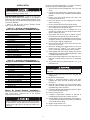
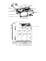
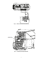
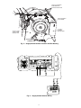
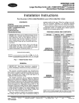
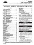
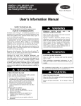
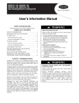
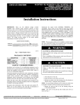
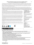
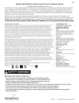
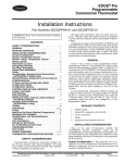
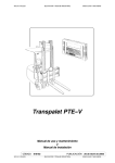
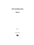
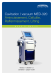
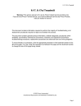
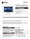
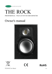
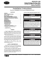
48/50HG014-028
Single-Package Rooftop Units
Accessory Return and Supply
Smoke Detectors
Installation Instructions
Part No. CRSMKDET001C00 and CRSMKSUP001A00
CONTENTS
GENERAL . . . . . . . . . . . . . . . . . . . . . . . . . . . . . . . . . . . . . . . . 1
SAFETY CONSIDERATIONS . . . . . . . . . . . . . . . . . . . . . . 1
INSTALLATION . . . . . . . . . . . . . . . . . . . . . . . . . . . . . . . . . 2-5
Check Package Contents. . . . . . . . . . . . . . . . . . . . . . . . . 2
Return Air Smoke Detector Installation. . . . . . . . . . . 2
Supply Air Smoke Detector Installation . . . . . . . . . . 5
Configuring the ComfortLink™ Controller. . . . . . . . 5
OPERATION . . . . . . . . . . . . . . . . . . . . . . . . . . . . . . . . . . . . .5,6
MAINTENANCE . . . . . . . . . . . . . . . . . . . . . . . . . . . . . . . . . . 7
Cleaning Procedure . . . . . . . . . . . . . . . . . . . . . . . . . . . . . . 7
Filter Replacement . . . . . . . . . . . . . . . . . . . . . . . . . . . . . . . 7
Board Replacement . . . . . . . . . . . . . . . . . . . . . . . . . . . . . . 7
TROUBLESHOOTING. . . . . . . . . . . . . . . . . . . . . . . . . . . .7,8
Smoke Entry Tests . . . . . . . . . . . . . . . . . . . . . . . . . . . . . . . 7
• AIRFLOW TEST
• SMOKE RESPONSE TEST
Standby, Alarm and Sensitivity Tests. . . . . . . . . . . . . 8
• STANDBY AND TROUBLE TEST
• ALARM TESTS
• SENSITIVITY TEST
GENERAL
An HVAC (heating, ventilation and air-conditioning) system supplies conditioned air to virtually every area of a
building. Smoke introduced into this air duct system will be
distributed throughout the entire building. Smoke detectors
designed for use inside the unit are used to sense the presence
of smoke passing through the unit.
The smoke detector utilizes photoelectric technology for the
detection of smoke. This detection method, when combined
with an efficient ducting design, samples air passing through
the unit. If sufficient smoke is sensed, an alarm signal is initiated and the ComfortLink controls will shut down the unit. With
the unit shut down, the unit will not blow toxic smoke and fire
gases throughout the areas served by the duct system.
The return air smoke detector is part number
CRSMKDET001C00. The supply air smoke detector is part
number CRSMKSUP001A00.
SAFETY CONSIDERATIONS
Follow all safety codes. Wear safety glasses and work
gloves. Use care when handling and installing the accessory.
Before performing service or maintenance operations on
unit, turn off main power switch to unit. Electrical shock
could cause personal injury.
The National Fire Protection Association has established
that DUCT DETECTORS MUST NOT BE USED AS A
SUBSTITUTE FOR OPEN AREA DETECTOR PROTECTION as a means of providing life safety. Nor are they
a substitute for early warning in a building’s regular fire
detection system. Carrier supports this position and strongly
recommends that the user read NFPA Standards 90A, 72,
and 101. This smoke detector is listed per UL 268A.
This device will not operate without electrical power.
Fire situations may cause an interruption of power. The
system safeguards should be discussed with your local fire
protection specialist.
This device will not sense smoke unless the ventilation system is operating and the cover is installed.
For this detector to function properly, it MUST be installed
according to the instructions in this manual. Furthermore,
the detector MUST be operated within ALL electrical and
environmental specifications listed in this manual. Failure
to comply with these requirements may prevent the detector from activating when smoke is present in the air duct.
Installation and servicing of air-conditioning equipment can
be hazardous due to system pressure and electrical components. Only trained and qualified service personnel should
install, repair, or service air-conditioning equipment.
Untrained personnel can perform the basic maintenance
functions of cleaning coils and filters and replacing filters. All
other operations should be performed by trained service personnel. When working on air-conditioning equipment, observe
precautions in the literature, tags and labels attached to the unit,
and other safety precautions that may apply.
Manufacturer reserves the right to discontinue, or change at any time, specifications or designs without notice and without incurring obligations.
PC 111
Catalog No. 534-80096
Printed in U.S.A.
Form 48/50HG-19SI
Pg 1
2-02
Replaces: 48/50HG-17SI
Book 1 1 4 4
Tab 1a 1b 6a 6b
INSTALLATION
NOTE: For horizontal applications it is easiest to install the
smoke detector prior to making duct connections.
1. Open the hinged electrical/compressor access door and
secure.
2. Find the 2 plugs located above compressor B1, remove
and discard. Cut holes in the insulation located behind the
partition.
3. Remove cover from smoke detector. The screws will
remain captured in the cover.
4. Place foam gaskets over each sampling tube on smoke
detector. (See Fig. 1.)
5. Remove one knockout from top of smoke detector.
6. Insert stripped ends of wire harness through knockout and
wire to smoke detector as shown in Fig. 3.
7. Provide strain relief for wires by attaching wire tie to
ground screw located next to the knockout in the smoke
detector. Tighten the wire tie.
8. Slide smoke detector into holes in partition with the
terminal block to the right. Do not secure at this time.
9. Slide sampling tube into left-hand hole of smoke detector.
It might be necessary to tilt the smoke detector upwards
in order properly align the sampling tube.
10. Remove the unit side panel at the return end of the unit.
Save screws for use later.
11. Mount the sampling tube support bracket to the cross
member with two 1/4AB-14 5/8-in. screws as shown
in Fig. 4. Insert large snap bushing into hole in bracket.
12. Slide sampling tube into bracket, making sure that the
sampling holes point down. Pull the sampling tube so that
it is flush with the smoke detector.
13. Return to Electrical/Compressor section and secure sampling tube to smoke detector with two no. 6 self-tapping
screws.
14. Attach smoke detector to partition using two, 8-18 3/4-in.
pan head screws.
When installing the smoke detector in the unit, follow all
local codes. Damage to unit may result.
Check Package Contents — Remove accessory packaging and inspect shipment for damage. If any damage is
found, file a claim with the shipping agent immediately. If any
item is missing or any part does not assemble properly, notify
your Carrier distributor.
Tables 1A and B list the accessory package contents.
Figure 1 shows the smoke detector.
Table 1A — Accessory Package Contents —
Return Air Smoke Detector (CRSMKDET001C00)
ITEM
Smoke Detector with Cover
Sampling Tube (long)
Sampling Tube Filters
Test Magnet
Foam Gaskets
Screw, no. 6 Self Tapping
Tube End Plug (large)
Sampling Tube Support Bracket
Screw, 8-18 3/4-in. Pan Head
Screw, 1/4AB-14 5/8-in.
Small Snap Bushing
Large Snap Bushing
Harness Assembly (4-Wires, short)
Wire Tie, Screw Mounted
QUANTITY
1
1
2
1
2
2
1
1
2
2
1
1
1
1
Table 1B — Accessory Package Contents —
Supply Air Smoke Detector (CRSMKSUP001A00)
ITEM
Smoke Detector with Cover
Sampling Tube (short)
Sampling Tube Filters
Test Magnet
Foam Gaskets
Tube End Plug (small)
Screw, 8-18 3/4-in. Pan Head
Small Snap Bushing
Harness Assembly (4-Wires, long)
Wire Tie, Screw Mounted
Wire Tie
Screw, no. 8 Self Tapping
Screw, no. 10
QUANTITY
1
1
2
1
2
1
2
1
1
5
1
1
2
Do not overtighten the screws. Damage to smoke detector
may result.
15. Return to side panel and insert tube end plug into
sampling tube.
16. Replace the unit side panel.
17. Return to Electrical/Compressor section and insert
sampling tube filters into both sampling tube holders.
(See Fig. 1.)
18. Install the snap bushing in the center knockout underneath the control terminal strips located in the bottom
right-hand corner of the control box.
19. Feed wires through snap bushing and connect to appropriate terminals as shown in Fig. 3.
20. Restore power to the unit.
21. Configure ComfortLink™ controller as specified in
Configuring the ComfortLink Controller on page 5.
22. Perform Standby, Alarm, and Sensitivity Tests on page 7.
At a minimum, the Magnet test should be performed to
verify smoke detector wiring.
23. Replace smoke detector cover.
24. Check for alarms. Correct any problems.
Return Air Smoke Detector Installation —
The return air smoke detector is to be installed in the predrilled
holes located above compressor B1 in the electrical/
compressor section (Fig. 2).
Prior to installation of this accessory, make sure all power
is disconnected to the unit and locked out. Failure to disconnect power supply prior to servicing may result in serious injury.
2
FOAM
GASKETS
CONDUIT HOLES
SAMPLING TUBE
FILTERS
PLASTIC
SAMPLING TUBE
DETECTOR
HOUSING
TERMINAL STRIP
POWER BOARD
PLASTIC SAMPLING TUBE
SELF-TAPPING SCREW
COVER MOUNTING
SCREWS
DETECTOR BOARD
DETECTOR COVER
Fig. 1 — Smoke Detector
SMOKE DETECTOR
Fig. 2 — Return Air Smoke Detector Location
3
Fig. 3 — Return Air Smoke Detector Wiring
SAMPLING TUBE
SUPPORT BRACKET
Fig. 4 — Sampling Tube Support Bracket
4
Supply Air Smoke Detector Installation —
The supply air smoke detector is to be installed in the predrilled holes located on the front of the first indoor blower
(Fig. 5).
20.
21.
22.
23.
Prior to installation of this accessory, make sure all power
is disconnected to the unit and locked out. Failure to
disconnect power supply prior to servicing may result in
serious injury.
24.
25.
1. Open the indoor fan access door and secure.
2. Open the hinged electrical/compressor access door and
secure.
3. Disconnect wires located on the left-hand side of the fan
deck. On 48HG units, the indoor fan plug and the limit
switch quick connects must be disconnected. On 50HG
units, only the indoor fan plug must be disconnected.
4. Find the 2 plugs located in the blower side plate. Remove
the plugs and discard. It will be necessary to remove
some of the tape holding the plugs in place.
5. Remove cover from smoke detector. The screws will
remain captured in the cover.
6. Place foam gaskets over each sampling tube on smoke
detector. See Fig. 1.
7. Remove one knockout from top of smoke detector.
8. Insert stripped ends of wire harness through knockout and
wire to smoke detector as shown in Fig. 6.
9. Provide strain relief for wires by attaching wire tie to
ground screw located next to the knockout in the smoke
detector. Tighten wire tie.
10. Secure sampling tube in inlet closest to the smoke detector electronics using the no. 8 self-tapping screw provided. See Fig. 1 for an example on how to connect a sampling tube. Be sure to connect the sampling tube to the
middle hole. Insert plug into the end of the sampling tube.
11. Slide smoke detector into holes in partition with the terminal block at the top and secure using two, 8-18 3/4-in.
pan head screws.
26.
27.
28.
29.
top of the filter section, down the outside of the control
box and through the snap bushing. See Fig. 5 and 6.
Connect wires to terminal strips as shown in Fig. 5 and 6.
Restore power to the unit.
Configure ComfortLink™ controller as specified in Configuring the ComfortLink Controller below.
Perform Standby, Alarm, and Sensitivity Tests on
page 7. At a minimum, the Magnet test should be performed to verify smoke detector wiring.
Turn off power to the unit.
Replace smoke detector cover. Do not overtighten
screws.
Reconnect the indoor fan plug and the limit switch wires
if applicable.
Close the indoor fan section door.
Restore power to the unit and check for alarms. Correct
any problems encountered.
Close Electrical/Compressor section door.
Configuring the ComfortLink Controller —
Configuration settings for the ComfortLink controller are
changed by using the Scrolling Marquee Display. A password
may be required to edit the configurations, depending on the
previous settings configured in the unit. Default password is
“1111”. Use the arrow keys to scroll the red LED on the display to the “Configuration” position and press ENTER . Scroll
through the menu until UNIT is found and press ENTER .
After reaching the UNIT sub-menu, scroll to FS.SW (Fire
Shutdown Input) and press ENTER twice, change the value
to 1 (Normal Open) with the arrow keys, press ENTER again.
Press ESCAPE three times to return to the top level of the
menu. Additional information about changing configurations
can be found in the Control and Troubleshooting Guide for
48/50HG units.
OPERATION
The smoke detector must be tested and maintained regularly following NFPA 72 requirements. The smoke detector
should be cleaned at least once a year. Damage to equipment may result.
Do not overtighten screws. Damage to smoke detector may
result.
The smoke detector accessories contain a photoelectric
detector approved for an extended air speed range of 100 to
4000 feet per minute (0.5 to 20.3 m/s) and an operational temperature range of 32 to 131 F (0° to 55 C). Do not operate the
smoke detector out of these ranges.
The smoke detector operates on 24 VAC, 120 VAC, or
240 VAC. The thermostat power terminals on the unit are used
to power the smoke detector. Alarm and supervisory relay contacts are available for control panel interface (alarm initiation),
HVAC control, and other auxiliary functions. Auxiliary relays
are also provided for fan shut down or signaling of up to 9
other detectors in the loop for multiple fan shut down. The
smoke detector is not designed for 2-wire applications.
The smoke detector can be reset by a momentary power interruption, by the reset button on the front cover, by the control
panel, or by the remote reset accessory. The smoke detector
incorporates a cover tamper feature that provides a trouble
signal after 20 minutes if the cover is removed or improperly installed. Proper installation of the cover removes the trouble condition.
12. Insert sampling tube filters into both sampling tube
holders. See Fig. 1.
13. Remove and save the two screws securing the indoor fan
sled to the unit.
14. Slide the indoor fan sled out until the back side of the first
blower is accessible.
15. Attach wire harness to fan side plate using the 4 screw
wire ties and no. 10 screws provided. See Fig. 5 for
clarification.
16. Slide in the indoor fan deck and secure using screws
saved from Step 13.
17. Attach wire harness to top of Circuit C filter drier (and
point B if two circuits) in Fig. 5, using wire tie provided.
Make sure that the wire harness is tight.
18. In the Electrical/Compressor section, install snap bushing
in the center knockout underneath the terminal strips located in the bottom right-hand corner of the control box.
19. Route wires from the filter drier to the control box. Wires
should follow existing wires through grommet located on
5
USE #10 SCREWS
PROVIDED TO
ATTACH WIRE TIES
ROUTE WIRES
AS SHOWN
SUPPLY
SMOKE
DETECTOR
SUPPLY FAN,
VIEW FROM
INSIDE UNIT
Fig. 5 — Supply Smoke Detector Location and Wire Routing
Fig. 6 — Supply Smoke Detector Wiring
6
MAINTENANCE
5. Secure board with the two mounting screws.
6. Re-connect wiring to terminal block.
Cleaning Procedure — Notify the proper authorities
that the smoke detector system is undergoing maintenance, and
that the system will temporarily be out of service. Disable the
zone or system undergoing maintenance to prevent unwanted
alarms and possible dispatch of the fire department.
AIR FILTERS
1. Turn off power to the system.
2. Remove and inspect sampling tube filters.
3. If filters are heavily coated with dirt, replace them with
new filters. If they are not heavily coated, use a vacuum
cleaner or compressed air nozzle to remove dust, then
reinstall the filters.
PHOTO DETECTOR BOARD
1. Remove the screen by gently grasping on each side and
pulling straight off.
2. Lift the photo chamber in the same fashion. Vacuum the
screen and cover. Use clean, compressed air to loosen and
blow out any remaining debris.
3. Vacuum photo chamber, then use clean compressed air to
blow area clean.
4. Replace the chamber by pressing it onto the base. Press
the screen into place. It should fit tightly on the chamber.
TROUBLESHOOTING
Test and maintain unit smoke detectors as recommended
in NFPA 72. Before conducting these tests, notify the proper
authorities that the smoke detection system will be temporarily
out of service. Disable the system under test to prevent unwanted alarms.
Smoke Entry Tests
AIRFLOW TEST — The smoke detector is designed to operate over an extended air speed range of 100 to 4000 fpm. To
verify sufficient sampling of unit air, turn on the 48/50HG unit
indoor fan using the Service Test function (see Controls and
Troubleshooting Guide for details on Service Test) and use a
manometer to measure the differential pressure between the
two sampling tubes.
The differential pressure should measure at least
0.0015 in. wg and no more than 1.2 in. wg. Because most commercially available manometers cannot accurately measure
very low pressure differentials, applications with less than
500 fpm of unit air speed may require the use of a currentsourcing pressure transmitter or the use of aerosol smoke (see
Smoke Response Test below).
SMOKE RESPONSE TEST — Drill a 1/4-in. hole 3-ft
upstream from the unit smoke detector. Use the Service Test
function (see Controls and Troubleshooting Guide for details
on Service Test) to turn on the 48/50HG unit indoor fan.
Measure the air velocity with an anemometer. Air speed must
be at least 100 fpm. If the air speed is greater than 500 fpm, use
a conventional manometer to measure differential pressure between the sampling tubes.
Spray aerosol smoke into the unit through the 1/4-in. hole
for 5 seconds. Wait two minutes for the unit smoke detector to
alarm. If the unit smoke detector alarms, then air is flowing
through the detector. Remove the unit smoke detector cover
and blow out the residual aerosol smoke from the chamber and
reset the unit smoke detector. Use duct tape to seal the aerosol
smoke entry hole.
To determine if smoke is capable of entering the sensing
chamber, visually identify any obstructions. Plug the exhaust
and inlet tube holes to prevent unit air from carrying smoke
away from the detector head, then blow smoke directly at the
head to cause an alarm.
Filter Replacement — The filters do not substantially
affect smoke detector performance even when up to 90% of the
filter is clogged. Quarterly visual inspection usually suffices to
determine whether the filters should be replaced. Only a high
percentage of contamination affects performance. If further
testing is required, compare differential pressure readings with
and without the filters installed. If the difference exceeds 10%,
then replace the filters. The pressure differential should never
fall below 0.0015 in. wg.
Board Replacement
SMOKE DETECTOR BOARD REPLACEMENT
1. Remove the two detector board mounting screws.
2. Pull gently on the board to remove it.
3. To replace the board, align the board mounting features,
holes, and the interconnect terminals. Push the board into
place.
4. Secure board with the two mounting screws.
POWER BOARD REPLACEMENT
1. Disconnect wiring from the terminal block.
2. Remove the two power board mounting screws.
3. Pull gently on the board to remove it.
4. To replace the board, align the board mounting features,
holes, and the interconnect terminals. Push the board into
place.
Remove the plugs after this test, or the smoke detector will
not function properly and damage may result.
7
Standby, Alarm and Sensitivity Tests — The cover of the smoke detector must be removed to perform these
tests.
STANDBY AND TROUBLE TEST
Standby — Look for presence of flashing green LED.
The LED should flash approximately every
10 seconds.
Trouble — If the detector LED does not flash, then the detector lacks power (check TB4), the detector board is
missing (replace), the cover has been missing or
not secured properly for more than 20 minutes
(secure cover properly), or the unit is defective
(return for repair).
Test —
The trouble condition can be caused intentionally
to verify correct operation of the system. Remove
the detector board to cause an alarm.
Cover
Tamper — If the cover is removed or not properly secured for
a period longer than 20 minutes, a trouble signal is
generated to indicate the cover is missing.
ALARM TESTS
Magnet Test
1. Place the painted surface of the magnet onto the TEST
locator on the bottom of the housing.
2. The red alarm LED on the detector should switch on.
Verify system control panel alarm status and control
panel execution of all intended auxiliary functions
(i.e., fan shutdown, damper control, etc.).
3. The detector must be reset by the front cover reset button.
SENSITIVITY TEST — After verification of alarm capability, use a field-supplied voltmeter to check detector sensitivity.
The housing cover must be removed to perform this test. If
readings indicate that the detector head is outside of the acceptable range that is printed on the label of the detector, the detector chamber requires cleaning.
Copyright 2002 Carrier Corporation
Manufacturer reserves the right to discontinue, or change at any time, specifications or designs without notice and without incurring obligations.
PC 111
Catalog No. 534-80096
Printed in U.S.A.
Form 48/50HG-19SI
Pg 8
2-02
Replaces: 48/50HG-17SI
Book 1 1 4 4
Tab 1a 1b 6a 6b