1
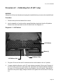
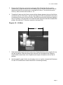
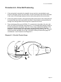
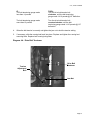
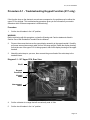
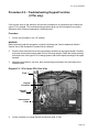
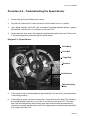
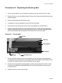
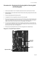
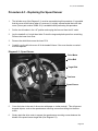
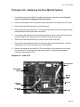
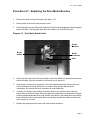
9.17, 917si Treadmill
9.17, 9.17si Treadmill
Warning: This service manual is for use by Precor trained service providers only.
If you are not a Precor Trained Servicer, you must not attempt to service any Precor Product;
Call your dealer for service.
This document contains information required to perform the majority of troubleshooting, and
replacement procedures required to repair and maintain this product.
This document contains general product information, software diagnostic procedures (when
available), preventative maintenance procedures, inspection and adjustment procedures,
troubleshooting procedures, replacement procedures and electrical block and wiring diagrams.
To move directly to a procedure, click the appropriate procedure in the bookmark section to the
left of this page. You may “drag” the separator bar between this page and the bookmark section
to change the size of the page being viewed.
© 2003 Precor Incorporated
Unauthorized Reproduction and Distribution Prohibited By Law.
Page 1
917, 917si Treadmillr
Section One - Things You Should Know
About This Appendix
Section One, Things You Should Know. This section includes technical specifications and a
procedure matrix. Read this section, as well as the 917, 917si Treadmill Owner’s Manual, before
you perform the maintenance procedures in this manual.
Section Two, Software Features. Precor’s 917si Treadmill is programmed with several
diagnostic and setup features. This section contains the procedures you need to access the
diagnostic features on this treadmill.
Section Three, Checking Treadmill Operation. This section provides you with a quick way of
checking treadmill operation. Check treadmill operation at the end of a maintenance procedure
and when it is necessary to ensure that the treadmill is operating properly.
Section Four, Inspection and Adjustment Procedures. Perform inspection procedures when
a trouble symptom points to a particular problem and after removing and replacing major
components. Many maintenance problems can be fixed by adjusting various treadmill
components. This section also provides you with the step-by-step procedures required to make
these adjustments.
Section Five, Troubleshooting Procedures. The diagnostic and troubleshooting procedures
contained in this section should be performed when it is necessary to isolate a problem to a
particular component.
Section Six, Replacement Procedures. When a treadmill component must be replaced, go to
this section and follow the step-by-step procedures required to remove and replace the
component.
Section Seven, Wiring and Block Diagrams. This section includes wiring and block diagrams
for 917 and 917si Treadmill.
General Information
For the latest exploded view, part number and part pricing information, visit the Precor dealer
website at “www.precor.com/Dealer”.
Page 2
9.17, 917si Treadmill
Technical Specifications
PHYSICAL SPECIFICATIONS
Length:
Width:
Height:
Running surface:
Motor:
Speed:
Incline:
Power:
Weight:
Shipping weight:
60 inches (152 cm)
28 inches (71 cm)
48 inches (122 cm)
18 X 54 inches (46 X 137 cm)
2.0 hp continuous duty
1.0 to 10 mph (1.6 to 16 kph)
10 mph is equivalent to a 6 minute mile
0 to 10% grade
120 Vac, 50/60 Hz
240 Vac, 50/60 Hz
150 lbs (68 kg)
160bs (75.6 kg)
ELECTRONIC SPECIFICATIONS
917 Programs:
Manual
917Si Programs:
Manual
Interval
Weight Loss
6 Pre-programmed courses (3 Walk, 3 Run)
2 Custom courses
Random
Heart Rate Course
Options
Polar Heart Rate System
Handrails
Page 3
917, 917si Treadmillr
Procedure 2.1 - Accessing the Diagnostic Program
(917si only)
The keys on the display are hypothetically numbered for 1 to 7 from left to right. Therefore,
INCLINE ▲ would be key 1, INCLINE ▼ would be key 2, etc.
Placing the unit in the diagnostic mode causes the software to perform the following operations:
a.
Test the LED’s mounted on the upper PCA;
b.
Provide the option of calibrating the lift system;
c.
Display the drive motor power bits;
d.
Test the keyboard;
e.
Display and test the heart rate function;
1.
Plug the power cord into the wall outlet, then turn on the treadmill with the circuit breaker.
2.
Press keys RESET,5,1,7,6,5,7,6,1, sequentially.
3.
All of the LED’s on the display will light up. Any LED segment that is not lit is defective.
Press the SELECT key to continue.
4.
After the LED test, the electronic console displays the potentiometer increment number.
5.
Verify that the running bed inclines and declines as the INCLINE ▲ or INCLINE ▼ keys are
pressed.
6.
When the potentiometer increment number is displayed on the electronic console, the
potentiometer increment number will track the incline as it is operated. Press the SELECT
key to continue.
7.
The power bit number will be displayed.
Note:
When the running belt is started, the number of power bits will be displayed. Power bits represent
the amount of power applied to the drive motor. Power bits are the product of selected speed and
applied load.
8.
Press the SPEED ▲ or SPEED ▼ key. Verify that the power bits number increments and
decrements as the SPEED keys are pressed. The Select key will toggle the display
between the power bit reading and a mile (or kilometer) per hour reading.
9.
Press the STOP key to exit the power bits mode.
Page 4
9.17, 917si Treadmill
10. A series of dots will appear on the display. Press each of the keys on the keyboard, the
appropriate dot will expand to indicate that the key is functioning. Press and hold the STOP
key to continue.
11. If the heart rate option has been installed, you may test the heart rate function using a chest
strap transmitter or test transmitter. Press the “SELECT to select U, F, or P heart rate mode.
U is unfiltered mode, F is filtered mode and P is Polar mode. The unfiltered mode will display
an unmodified heart rate directly from the heart rate transmitter, the filtered mode will
display the heart rate averaged over a short period of time and the Polar mode will utilize a
Polar filtering system.
12. Press the STOP key to exit the diagnostics program.
Diagram 2.1 - 917si Display
Key 1
Key 2
Key 3
RESET
Key 5
Key 6
Key 7
Page 5
917, 917si Treadmillr
Procedure 2.2 - Displaying the Odometer
(917si only)
The keys on the display are hypothetically numbered for 1 to 7 from left to right. Therefore,
INCLINE ▲ would be key 1, INCLINE ▼ would be key 2, etc.
This procedure allows you to display the number of miles or kilometers logged on the treadmill.
Procedure
1.
Plug the power cord into the wall outlet, then turn on the treadmill with the circuit breaker
2.
Press keys RESET,6,5, sequentially.
3.
The console displays the number of miles or kilometers logged on the treadmill. Press the
STOP key to continue.
4.
The total number of hours the treadmill drive motor has been operating will be displayed.
Press the STOP key to continue.
5.
The software version will be displayed. Press the STOP key to continue.
6.
The error code log will be displayed. There may be up to ten error codes logged. The error
code and the odometer reading when the error occurred will be displayed. Use either ▲ to
move forward through the error code log position. Use either ▼ to backward through the
error code log.
7.
If you no longer require the contents of the error code log for troubleshooting and wish to
clear the error code log, press the STOP and QUICK START keys, simultaneously.
8.
Press the STOP to exit.
Page 6
9.17, 917si Treadmill
Procedure 2.3 - Selecting United States Standard or Metric
Units (917si only)
The keys on the display are hypothetically numbered for 1 to 7 from left to right. Therefore,
INCLINE ▲ would be key 1, INCLINE ▼ would be key 2, etc.
Selecting United States standard units causes information to be displayed in feet, miles and
pounds. Information is displayed in meters, kilometers and kilograms if metric units are selected.
After you have selected a measurement standard, the software compiles and records workout
information in the units of the measurement standard selected. Changing to the alternate
measurement standard after your workout has started will cause invalid data to be displayed. For
this reason, change the measurement standard only after turning ON the treadmill.
Procedure
1.
Plug the power cord into the wall outlet, then turn on the treadmill with the circuit breaker.
2.
With the Enter Your Weight banner scrolling, press keys RESET,5,6,7, sequentially.
3.
The current setting, either U.S. Standard or Metric will be displayed.
4.
Use the ▲ or ▼ keys to select the desired unit of measurement setting.
5.
Press the STOP key to exit,
Page 7
917, 917si Treadmillr
Procedure 2.4 - Documenting Software Problems
When a problem is found with either the PROM or upper or lower PCA’s, record the information
listed below. If you isolated the problem to either the PROM, upper PCA, or lower PCA, include
the information with the malfunctioning PROM or PCA when you ship it to Precor Customer
Service.
When a problem occurs, record the following information:
•
Model and serial number.
•
Software version number.
•
User and program number running when the problem occurred.
•
A description of:
•
a.
What happened or failed to happen.
b.
The action taken by the user just before the problem occurred.
c.
Problem-related information (such as how far into the program the problem occurred,
the work level being used when the problem occurred, etc.)
The frequency of occurrence.
Page 8
9.17, 917si Treadmill
Section Three - Checking Treadmill Operation
This section provides you with a quick method of checking treadmill operation. Check treadmill
operation at the end of a maintenance procedure and when it is necessary to ensure that the
treadmill is operating properly.
Procedure
1.
Plug the power cord into the wall outlet, then turn on the treadmill with the circuit breaker.
2.
Adjust the speed of the running belt to 2–3 mph.
3.
Operate the treadmill for at least 5 minutes.
a.
Check the running belt alignment. If necessary, adjust the running belt tracking per
Procedure 4.3.
b.
Concentrate on the feel of the running belt and the sound of the drive motor and rollers.
Be alert for running belt or drive belt slippage, unusual noises, smells, or vibrations.
c.
Measure and log the AC input current under loaded and unloaded conditions.
4.
Press the INCLINE ▲ key while viewing the electronic console. Confirm that the running
bed inclines and the incline display increments to 10 percent as the INCLINE ▲ key is
pressed.
5.
Press the INCLINE ▼ key while viewing the electronic console. Confirm that the running bed
returns to a level position and the incline display decrements to zero percent as the
INCLINE ▼ key is pressed.
6.
Check for targa looseness. The targa should not move back and forth with your body
weight. The targa should not creak or rattle as the treadmill is used.
7.
Inspect the running deck trim strips for looseness. The running deck trim strips must be
securely snapped into place.
Turn off the treadmill with the circuit breaker, then unplug the treadmill from the wall outlet.
Page 9
917, 917si Treadmillr
Procedure 4.1 - Calibrating the Lift (917 only)
WARNING
Always turn off the circuit breaker and unplug the treadmill before you remove the treadmill hood.
Procedure
1.
Remove the top front and bottom front covers.
2.
Lay the treadmill on it’s side and the unsnap lift platform wheel axle from the lift platform.
Remove the wheels and axle from the lift motor tube. See Diagram 4.1.
Diagram 4.1 - Lift Platform
Lift Platform
Wheel (4)
Lift Platform Axle
Lift Motor Tube
3.
Plug the AC line cord into an AC outlet and set the circuit breaker in the “on” position.
4.
Connect a digital multimeter, set for DC volts, between terminals 5 (blue) and 6 (brown) of
the P7 lift motor connector on the lower PCA. Operate the lift until the voltmeter reading is
as close to 0.35 Vdc as possible. Set the circuit breaker in the “off” position. Allow about 5
seconds for the power supply voltage to bleed off, the green LED on the lower PCA will go
out.
Page 10
9.17, 917si Treadmill
5.
Remove the P7 lift motor connector from the lower PCA. Thread the lift tube counterclockwise far enough so that you can comfortably grasp the lift motor drive screw. Set the
digital multimeter for ohms and leave it connected as in step 4. Turn the lift motor drive
screw, by hand, until the meter reads 98 ± 2Ω.
6.
Thread the lift tube onto the lift drive screw until the distance between the top of the lift tube
and the lift motor is 6-3/4 inches ± 1/8 inch. See Diagram 4.2 Be sure that the lift motor drive
screw does not turn as you turn the lift tube. If the drive screw turns the resistance reading in
step 5 will change. The ohmmeter must reads 98Ω after the lift tube has been threaded into
position. Re-insert the P7 lift motor connector in the lower PCA.
Diagram 4.2 - Lift Motor
6-3/4”
7.
Slide the lift platform axle into the lift motor tube. Rotate the lift tube only enough to line up
with the lift platform. Slide two wheels onto each end of the lift platform axle. Align the
wheels with the wheel slots in the lift platform and snap the lift platform axle into the lift
platform.
8.
Set the treadmill upright. Set the circuit breaker in the “on” position. Operate the lift between
0% and 10% several time to ensure that the lift is functioning normally.
Page 11
917, 917si Treadmillr
Procedure 4.2 - Calibrating the Lift (917si only)
WARNING
Always turn off the circuit breaker and unplug the treadmill before you remove the treadmill hood.
Procedure
1.
Lay the treadmill on it’s side and unsnap the lift platform wheel axle from the lift platform.
Remove the wheels and axle from the lift motor tube. See Diagram 4.1.
2.
Set the circuit breaker in “on” position. Access the diagnostics program, as in Procedure 2.1,
and proceed to the lift potentiometer increment number. Operate the lift until the lift
potentiometer increment number is 20.
3.
Thread the lift tube onto the lift drive screw until the distance between the top of the lift tube
and the lift motor is 6-3/4 inches ± 1/8 inch. See Diagram 4.2 Be sure that the lift motor drive
screw does not turn as you turn the lift tube. If the drive screw turns the potentiometer
increment number in step 3 will change. The potentiometer increment number must be 20
after the lift tube has been threaded into position.
4.
Exit the diagnostic program and set the circuit breaker in the “off” position.
5.
Slide the lift platform axle into the lift motor tube. Rotate the lift tube only enough to line up
with the lift platform. Slide two wheels onto each end of the lift platform axle. Align the
wheels with the wheel slots in the lift platform and snap the lift platform axle into the lift
platform.
6.
Set the treadmill upright. Set the circuit breaker in the “on” position. Operate the lift between
0% and 10% several time to ensure that the lift is functioning normally.
Page 12
9.17, 917si Treadmill
Procedure 4.3 - Running Belt Tensioning and Tracking
WARNING
Always turn off the circuit breaker and unplug the treadmill before you remove the treadmill hood.
1.
The basic running belt tensioning and tracking procedure described in the Residential
Treadmill service manual (part # 20081-101) may be used to tension and track the 917 or
917si treadmill with a few exceptions.
2.
The drive roller on the 917 and 917si is a “fixed” mount. The drive roller is not moveable or
adjustable and does not play a part in the running belt tracking procedure.
3.
The 917 and 917si treadmills use belt guides. The belt guides make the tracking procedure
easier in that the adjustment does not need to be as exacting without the belt guides.
4.
The 917 and 917si running belt tension is 0.3%.
Page 13
917, 917si Treadmillr
Procedure 4.4 - Drive Belt Tensioning
1.
If the running bed is mounted in the treadmill, it may need to be moved slightly to gain
access to the upper surface of the drive belt. The drive belt tension test must be performed
in the center of the belt span between the drive roller pulley and the drive motor pulley.
2.
If the running bed is mounted, running bed belt guides on the bottom of the running bed and
the screws that mount the running bed to the frame. Lift and slide the running bed just far
enough out of the right side of the running belt to expose the drive belt.
3.
Place a belt gauge (Precor part # 20030-117 or equivalent) in the middle of the drive belt
and in the center of the belt span (see Diagram 5.3). Lay a straight edge along the length of
the belt and beside the belt gauge. Slide one of the o-rings up against the shoulder of the
belt gauge. Press downward on the belt gauge, causing the belt to deflect. Read the
deflection on the belt gauge at the edge of the straight edge. Deflect the belt 1/2”. Read the
tension across the top edge of the o-ring. If the belt is correctly tensioned the gauge will
read between 14 and 16 pounds. See Diagram 4.3.
Diagram 4.3 - Drive belt Tension Gauge
15 lbs
1/2”
Page 14
9.17, 917si Treadmill
IF...
The belt tensioning gauge reads
less than 14 pounds
THEN...
Turn the drive belt tension bolt
clockwise, until the belt tensioning
gauge reads 14-16 pounds @1/2” deflection.
The belt tensioning gauge reads
more than 16 pounds
Turn the drive belt tension bolt
counterclockwise, until the belt
tensioning gauge reads 14-16 pounds @ 1/2”
deflection.
4.
When the belt tension is correctly set tighten the jam nut to lock the tension setting.
5.
If necessary, slide the running bed back into place. Replace and tighten the running bed
mounting bolts. Replace both running belt guides.
Diagram 4.4 - Drive Belt Tensioner
Tension
Adjustment
Bolt
Drive Belt
Tensioner
Jam Nut
Page 15
917, 917si Treadmillr
Procedure 5.1 - Troubleshooting Keypad Function (917 only)
If the function keys on the electronic console are unresponsive, the problem may be either the
upper PCA or keypad. This troubleshooting procedure gives you the information you need to
determine which of these components is malfunctioning.
Procedure
1.
Set the circuit breaker in the “off” position.
WARNING
Before continuing with this procedure, review the Warning and Caution statements listed in
Section One of the Residential Treadmill Service Manual.
2.
Remove the screws that secure the upper display assembly to the upper handrail. Carefully,
pull some excess interconnect cable out from the targa upright. Rotate the display housing,
so that the rear of the upper PCA is facing upward, and set the display housing on the upper
handrail.
3.
Attach the wrist strap to your arm, then connect the ground lead of the wrist strap to the
treadmill frame.
Diagram 5.1 - 917 Upper PCA, Rear View
Pin # 1
Keypad
Connector
Keypad
Cable
Interconnect
Cable
4.
Set the voltmeter to a range that will conveniently read +6 Vdc.
5.
Set the circuit breaker in the “on” position.
Page 16
9.17, 917si Treadmill
6.
Use a DVM, set for DC volts, and read between pin 6 of J2 and the each of the pins in Table
5.1 (no keys pressed) and Table 5.2 (with the appropriate key pressed)...
Table 5.1. Voltage Test Points (Function Keys Not Pressed)
Place the positive lead of the
voltmeter on...
Pin 3 of J2
Pin 4 of J2
Pin 5 of J2
Pin 7 of J2
Pin 8 of J2
Pin 9 of J2
The voltmeter should
read...
5 Vdc ± 500 mVdc
5 Vdc ± 500 mVdc
5 Vdc ± 500 mVdc
5 Vdc ± 500 mVdc
5 Vdc ± 500 mVdc
5 Vdc ± 500 mVdc
Table 5.2. Voltage Test Points (Function Keys Pressed)
Place the positive
voltmeter lead on...
Pin 3 of J2
Pin 4 of J2
Pin 5 of J2
Pin 7 of J2
Pin 8 of J 2
Pin 9 of J2
At the electronic
console, press...
SELECT/ENTER
INCLINE ▼
INCLINE ▲
STOP
SPEED ▼
SPEED ▲
The voltmeter should
read between...
0 Vdc and 500 mVdc
0 Vdc and 500 mVdc
0 Vdc and 500 mVdc
0 Vdc and 500 mVdc
0 Vdc and 500 mVdc
0 Vdc and 500 mVdc
7.
If the voltage readings match those listed in Tables 5.1 and 5.2 and one or more keys do not
function, replace the upper PCA.
8.
If the voltage readings in Table 5.1 are incorrect, disconnect the keypad cable from the key
pad connector and repeat the voltage measurements in 5.1. If the voltage readings are now
correct, replace the display housing (keypad). If the voltage readings are still incorrect,
replace the upper PCA.
9.
If the voltage readings in Table 5.1 are correct and one or more voltage readings in Table
5.2 are incorrect, replace the display housing (keypad).
10. Set the circuit breaker in the “off” position.
11. If necessary, carefully re-connect the keypad cable to the keypad connector.
12. Remove the ground lead of the wrist strap from the treadmill frame, then remove the wrist
strap from your arm.
13. Position the display enclosure on the display plate. Install the screws that secure the display
enclosure to the display plate.
14. Check the operation of the treadmill as described in Section Three of this appendix.
Page 17
917, 917si Treadmillr
Procedure 5.2 - Troubleshooting Keypad Function
(917si only)
If the function keys on the electronic console are unresponsive, the problem may be either the
upper PCA or keypad. This troubleshooting procedure gives you the information you need to
determine which of these components is malfunctioning.
Procedure
1.
Set the circuit breaker in the “off” position.
WARNING
Before continuing with this procedure, review the Warning and Caution statements listed in
Section One of the Residential Treadmill Service Manual.
2.
Remove the screws that secure the upper display assembly to the upper handrail. Carefully,
pull some excess interconnect cable out from the targa upright. Rotate the display housing,
so that the rear of the upper PCA is facing upward, and set the display housing on the upper
handrail.
3.
Attach the wrist strap to your arm, then connect the ground lead of the wrist strap to the
treadmill frame.
Diagram 5.2 - 917si Upper PCA, Rear View
Pin # 1
Keypad
Connector
Keypad
Cable
Interconnect
Cable
4.
Set the voltmeter to a range that will conveniently read +6 Vdc.
Page 18
9.17, 917si Treadmill
5.
Set the circuit breaker in the “on” position.
6.
Use a DVM, set for DC volts, and read between pin 6 of J3 and the each of the pins in Table
5.1 (no keys pressed) and Table 5.2 (with the appropriate key pressed)...
Table 5.1. Voltage Test Points (Function Keys Not Pressed)
Place the positive lead of the
voltmeter on...
Pin 3 of J3
Pin 4 of J3
Pin 5 of J3
Pin 7 of J3
Pin 8 of J3
Pin 9 of J3
Pin 10 of J3
The voltmeter should
read...
5 Vdc ± 500 mVdc
5 Vdc ± 500 mVdc
5 Vdc ± 500 mVdc
5 Vdc ± 500 mVdc
5 Vdc ± 500 mVdc
5 Vdc ± 500 mVdc
5 Vdc ± 500 mVdc
Table 5.2. Voltage Test Points (Function Keys Pressed)
Place the positive
voltmeter lead on...
Pin 3 of J3
Pin 4 of J3
Pin 5 of J3
Pin 7 of J3
Pin 8 of J3
Pin 9 of J3
Pin 10 of J3
At the electronic
console, press...
SELECT/ENTER
INCLINE ▼
INCLINE ▲
STOP
SPEED ▼
SPEED ▲
QUICK START
The voltmeter should
read between...
0 Vdc and 500 mVdc
0 Vdc and 500 mVdc
0 Vdc and 500 mVdc
0 Vdc and 500 mVdc
0 Vdc and 500 mVdc
0 Vdc and 500 mVdc
0 Vdc and 500 mVdc
7.
If the voltage readings match those listed in Tables 5.1 and 5.2 and one or more keys do not
function, replace the upper PCA.
8.
If the voltage readings in Table 5.1 are incorrect, disconnect the keypad cable from the key
pad connector and repeat the voltage measurements in 5.1. If the voltage readings are now
correct, replace the display housing (keypad). If the voltage readings are still incorrect,
replace the upper PCA.
9.
If the voltage readings in Table 5.1 are correct and one or more voltage readings in Table
5.2 are incorrect, replace the display housing (keypad).
10. Set the circuit breaker in the “off” position.
11. If necessary, carefully re-connect the keypad cable to the keypad connector.
12. Remove the ground lead of the wrist strap from the treadmill frame, then remove the wrist
strap from your arm.
13. Position the display enclosure on the display plate. Install the screws that secure the display
enclosure to the display plate.
14. Check the operation of the treadmill as described in Section Three of this appendix.
Page 19
917, 917si Treadmillr
Procedure 5.3 - Troubleshooting the Lift System
System Description
The lift system is powered by a 120 Vac lift motor that uses two independent motors windings,
one operates the motor in an upward direction and one operates the motor in a downward
direction. The motor contains a 1 KΩ potentiometer, driven by the motor, that indicates lift
position. AC power to operate the lift motor is provided by a pair of triacs. One triac provides
power to the “up” winding of the lift motor and the other triac provides power to the “down”
winding of the lift motor. The triacs are controlled either manually or by software control from the
upper PCA.
1.
If the lift motor will not move skip to step 8. If the lift motor moves and an error occurs
continue with step 2.
2.
For 917si treadmills, skip to step 3. For 917 treadmills, calibrate the lift per Procedure 4.1. If
the lift error still occurs, continue with step 4.
3.
Access the diagnostics program per Procedure 2.1 and proceed to the lift calibration portion
of the diagnostics program. If the lift calibration number is 0 or 255 skip to step 4. Operate
the lift, if the lift calibration number does not increment as the lift moves, skip to step 4. If the
calibration number increments as the lift moves, re-calibrate the lift per Procedure 4.2. If recalibration does not correct the problem, continue with step 4.
4.
Set the treadmill circuit breaker in the “off” position. Using an ohmmeter, measure between
terminal 4 (brown wire) and terminal 6 (orange wire) of the P7 connector on the lower PCA.
The measurement should be approximately 1 KΩ. If the measurement is open (∞) or
significantly high or low, replace the lift motor.
5.
Using an ohmmeter, measure between terminals 4 and 5 of P7 and measure between 5 and
6 of P7 on the lower PCA. The two measurements should total approximately 1 KΩ. If the
measurement is open (∞) or significantly high or low, replace the lift motor.
6.
If you have performed all of the above tests and an error still occurs when the lift motor
operates, there are three parts that could cause the problem. There are not any good tests
to check these parts other than substituting a known good part. They are lower PCA, ribbon
cable and upper PCA. Replace only one part at a time. If the new part does not correct the
problem replace the original part.
7.
If you have performed all of the above tests and the lift system is still not functioning, call
Precor Technical Support.
8.
Set the treadmill circuit breaker in the “off” position. Remove the F2 (2 amp slow blow) fuse
from the lower PCA. Measure the fuse with an ohmmeter. The measurement should be 1Ω
or less. If the fuse is good, re-insert the fuse and skip to step 10. If the fuse is open (∞)or
significantly high, replace the fuse. Before operating the lift motor it is necessary to perform
a continuity test on the lift motor.
Page 20
9.17, 917si Treadmill
9.
Remove the P7 connector from the lower board. Using an ohmmeter, measure between
terminals 1 and 3 of P7, between terminals 1 and 2 of P7 and between terminals 2 and 3 of
P7. The measurements should be approximately 49.5Ω, 47.5Ω and 97Ω, respectively. If any
of the measurements are significantly low or high, replace the lift motor.
10. Re-insert the P7 connector in the lower PCA. Set the treadmill circuit breaker in the “on”
position. Using an AC voltmeter, monitor the voltage between terminals 1 and 2 (red and
white wires) of the P7 connector. Enter the manual program and press the INCLINE ▲ key.
The measurement should be approximately 120 Vac (line voltage). If the voltage is present
and the lift motor moves normally, skip to step 10. The voltage will only be present until such
time as an error occurs. If line voltage is not present skip to step 11. If line voltage is
measured but the motor does not move, replace the lift motor.
11. Monitor terminals 1 and 3 (white and black wires) of P7. Enter the manual program and
press the INCLINE ▼ key. The measurement should be approximately 120 Vac (line
voltage). If the voltage is present and the lift motor moves normally skip to step 12. The
voltage will only be present until such time as an error occurs. If line voltage is measured but
the motor does not move, replace the lift motor.
12.
If line voltage is not present in both steps 9 and 10, there are three parts that could cause
the problem. There are not any good tests to check these parts other than substituting a
known good part. They are lower PCA, ribbon cable and upper PCA. Replace only one part
at a time. If the new part does not correct the problem replace the original part.
13.
If you have performed all of the above tests and the lift system is still not functioning, call
Precor Technical Support.
Page 21
917, 917si Treadmillr
Procedure 5.4 - Troubleshooting the Speed Sensor
1.
Remove the top front and bottom front covers.
2.
Plug the line cord into an AC outlet and set the circuit breaker in the “on” position.
3.
Use a digital voltmeter, set for DC volts, to measure the voltage between terminal 1 (green)
and terminal 2 (white) of the J1 connector on the lower PCA.
4.
Slowly rotate the drive motor, the voltage should alternately switch from near 0 Vdc to near
5 Vdc as the target disk passes through the speed sensor.
Diagram 5.3 - Speed Sensor
Drive Motor
Drive Belt
Target Disk
Tensioner
Speed Sensor
Motor Mounting
Bolts
5.
If the voltage in step 4 switches between approximately 0 Vdc and 5 Vdc, the speed sensor
is functioning correctly.
6.
If the voltage in step 4 is incorrect, remove the J1 connector from the lower PCA. Measure
the voltage between terminals 1 an 4 of the J1 connector on the lower PCA. Terminals 1
and 4 are the terminals that mate with the green and red wires when the speed sensor
connector is inserted into the lower board. If the voltage does not measure approximately 5
Vdc, replace the lower PCA.
Page 22
9.17, 917si Treadmill
7.
If the voltage in step 4 is incorrect and the voltage in step 6 is correct, either the speed
sensor or the lower PCA could be defective. Substitute a known good speed sensor and see
if that corrects the problem. If not, substitute a known good lower PCA.
8.
If you have performed all of the above tests and the speed sensor is still not functioning, call
Precor Technical Support.
Page 23
917, 917si Treadmillr
Procedure 5.5 - Troubleshooting the External A.C. Power
Source
It is extremely important that any Precor treadmill be connected to and operated on a dedicated
20 amp A.C. circuit. A 20 amp dedicated circuit is defined as: a circuit fed by a 20 amp circuit
breaker that feeds a single load. A treadmill operating from a non-dedicated circuit or a circuit
breaker of less than 20 amps capacity will not have the necessary power available to operate
normally under higher load conditions. The lack of available power can cause any number of
symptoms ranging from numerous intermittent (seemingly inexplicable) error conditions, poor
speed control, or tripping the house circuit breaker.
If any of the above symptoms exist the external A.C. circuit must be checked and confirmed to be
a 20 amp dedicated circuit before troubleshooting the treadmill.
In addition the A.C. voltage must be checked. Nominal A.C. operating voltage on 120 Vac circuits
is 105 Vac to 120 Vac. Nominal A.C. operating voltage on 240 Vac circuits is 208 Vac to 240
Vac.
For operator safety considerations and to minimize electrostatic discharge conditions the A.C.
frame ground continuity must also be verified to be a low resistance connection to the A.C.
distribution ground bar.
Important
If the A.C. circuit feeding a treadmill is found to be a non-dedicated circuit or a circuit equipped
with a circuit breaker with a capacity of less than 20 amps, the A.C. circuit must be corrected to
be a 20 amp dedicated circuit before any reliable troubleshooting can be performed on the
treadmill. More importantly, a non-dedicated circuit may constitute a safety hazard to the
treadmill operator.
120 Vac Systems
120 Vac distribution systems utilize a single pole circuit breaker (hot lead) and a neutral lead
connected to a common neutral (ground) bar. The A.C. safety ground (green wire) is connected
to a separate ground bar in the distribution system.
The most common problems found are (1) the circuit is fed by a circuit breaker of less than 20
amp capacity, (2) the circuit breaker correctly feeds a single A.C. outlet but the neutral is
common between several A.C. outlets and (3) both the hot and neutral leads feed several A.C.
outlets. The appropriate correction action or actions (see below) must be followed if any of the
above conditions exist. Corrective actions should only be undertaken by a licensed
electrician.
1.
The circuit breaker feeding the treadmill is not a 20 amp circuit breaker.
If the circuit breaker is greater than 20 amps, the circuit breaker should be replaced with a
20 amp circuit breaker. If the circuit breaker is less than 20 amps the circuit breaker must be
replaced with a 20 amp circuit breaker and the wiring from the A.C. distribution must be
capable of safely handing 20 amps. If the A.C. wiring is under sized, it must be replaced
with wire capable of safely handling 20 amps. Please, refer to local electrical codes when
determining the appropriate wire size for a 20 amp circuit.
Page 24
9.17, 917si Treadmill
2.
The circuit breaker correctly feeds a single A.C. outlet but the neutral is common
between several A.C. outlets.
The common neutral lead must be removed from treadmill’s A.C. outlet and a new neutral
lead from the treadmill’s A.C. outlet to the A.C. neutral distribution bar must be added.
3.
Both the hot and neutral leads feed several A.C. outlets.
Both the common neutral and hot leads must be removed from treadmill’s A.C. outlet and a
new neutral lead and hot lead from the treadmill’s A.C. outlet to the A.C. neutral distribution
bar and circuit breaker must be added.
240 Vac Systems
240 Vac distribution systems utilize a double pole circuit breaker (two hot leads) The A.C. safety
ground (green wire) is connected to a ground bar in the distribution system.
The most common problems found are (1) the circuit is fed by a circuit breaker of less than 20
amp capacity and (2) both the hot leads feed several A.C. outlets. The appropriate correction
action or actions (see below) must be followed if any of the above conditions exist. Corrective
actions should only be undertaken by a licensed electrician.
1.
The circuit breaker feeding the treadmill is not a 20 amp circuit breaker.
If the circuit breaker is greater than 20 amps, the circuit breaker should be replaced with a
20 amp circuit breaker. If the circuit breaker is less than 20 amps the circuit breaker must be
replaced with a 20 amp circuit breaker and the wiring from the A.C. distribution must be
capable of safely handing 20 amps. If the A.C. wiring is under sized, it must be replaced
with wire capable of safely handling 20 amps. Please, refer to local electrical codes when
determining the appropriate wire size for a 20 amp circuit.
2.
Both the hot leads feed several A.C. outlets.
Both hot leads must be removed from treadmill’s A.C. outlet and two new hot leads from the
treadmill’s A.C. outlet to the circuit breaker must be added.
A licensed electrician may use the followings hints to determine if an A.C. service is dedicated.
1.
If, on a 120 Vac system, the A.C. distribution panel contains more circuit breakers than
neutral leads, the system has shared neutral leads and is not dedicated.
2.
If an A.C. outlet (120 or 240 Vac) has multiple hot and/or neutral leads, it is not a dedicated.
If either of the above conditions exist, the system is not dedicated. However, absence of the
above conditions does not necessarily mean that the system is dedicated. If any doubt exists
about A.C. systems dedication, point to point tracing of the A.C. wiring may be the only way to
prove system dedication.
Page 25
917, 917si Treadmillr
Procedure 6.1 - Replacing the Running Bed
1.
Set the circuit breaker in the “off” position and remove the line cord from the AC outlet.
2.
Remove the four screws that retain the hood. Remove the hood by pulling the from the sides
and back slightly.
3.
Remove both endcaps and the take up roller.
4.
Unsnap both of the running bed trim strips from the running bed.
5.
Remove the screws that fasten the rear of the running bed to the treadmill frame.
6.
Lift the running bed straight up and two inches to the rear, to clear the drive roller pulley.
Slide the running bed out of the running belt taking care not to scratch the treadmill frame
with the belt trackers that are fastened to the bottom front of the running bed.
Diagram 6.1 - Running Bed
Hood
End Cap
Running Belt
Trim Strip
Targa
Left Side Cover
7.
Remove the belt trackers from the old running bed and mount them on the replacement
running bed. Set the replacement running bed in place in the treadmill, again taking care not
to scratch the treadmill frame as the running bed is slid into place.
8.
Replace the running bed and partially tighten mounting screws removed in step 5. Center
the running bed between the treadmill frame rails and securely tighten the running bed
mounting screws.
9.
Replace the take up roller and end caps.
Page 26
9.17, 917si Treadmill
10. Center the running belt on the running bed, be sure that the running belt is centered
between the belt trackers. Using two running belt tension gauges, tension the running belt to
0.3%
11. Snap the trim strips onto the side rails and slide them back under the end caps. The
Timmerman clips (hood mounting clips) must be fully visible with at least a 1/4” of clearance
on all sides.
12. Replace the hood.
13. Check the running belt tracking per Procedure 4.3.
14. Check treadmill operation per procedure 3.
Page 27
917, 917si Treadmillr
Procedure 6.2 - Replacing the Running Belt or Running Belt
and Running Bed
1.
Set the circuit breaker in the “off” position and remove the line cord from the AC outlet.
2.
Remove the four screws that retain the hood. Remove the hood by pulling the from the sides
and back slightly.
3.
Remove both endcaps and the take up roller.
4.
Unsnap both of the running bed trim strips from the running bed.
5.
Disconnect the interconnect cable from the lower PCA. Remove the six bolts that fasten the
targa to the treadmill frame and remove the targa. Care must be taken when removing the
targa to ensure that the interconnect cable is not damaged. See Diagram 6.1.
6.
Turn the drive belt adjustment bolt counter-clockwise until all tension is removed from the
drive belt. Remove both drive roller mounting bolts. Slide the drive belt off of the drive roller
and remove the drive roller. See Diagram 6.2.
7.
Remove the screws that fasten the rear of the running bed to the treadmill frame.
Diagram 6.2 - Drive Belt Tension Adjuster
Drive Belt
Tensioner
Jam Nut
Adjustment Bolt
Page 28
9.17, 917si Treadmill
8.
Lift the running belt and running bed straight up out of the treadmill frame.
9.
Set the replacement running belt and running bed in place in the treadmill frame.
10. Set the drive roller in place, be sure that drive belt is around the drive roller. Replace the two
drive roller mounting bolts. Slide the drive belt onto the drive roller pulley and tension the
drive belt per Procedure 4.4.
11. Partially tighten the running bed mounting screws removed in step 7. Center the running
bed between the treadmill frame rails and securely tighten the running bed mounting
screws.
12. Replace the take up roller and end caps.
13. Center the running belt on the running bed, be sure that the running belt is centered
between the belt trackers. Using two running belt tension gauges, tension the running belt to
0.3%
14. Snap the trim strips onto the side rails and slide them back under the end caps. The
Timmerman clips (hood mounting clips) must be fully visible with at least a 1/4” of clearance
on all sides.
15. Replace the hood.
16. Check the running belt tracking per Procedure 4.3.
17. Check treadmill operation per procedure 3.
Page 29
917, 917si Treadmillr
Procedure 6.3 - Replacing the Speed Sensor
1.
The left side cover (See Diagram 6.1) must be removed during this procedure. It is possible
that the cover will be broken when it is removed. It is highly recommended that a left side
cover (Precor part number 38088-101) is available before performing this procedure.
1.
Set the circuit breaker in the “off” position and unplug the line cord from the AC outlet.
2.
Lay the treadmill on it’s right hand side. Protect the targa and plastic parts from scratching.
Remove the lower front cover.
3.
Remove the shield that covers the lower PCA.
4.
Carefully, pry the left side cover off of the treadmill frame. If the cover breaks or cracks it
must be replaced.
Diagram 6.3 - Speed Sensor
Drive Motor
Drive Belt
Target Disk
Tensioner
Speed Sensor
5.
Cover the holes in the end of drive motor with paper or similar material. This will prevent
dropped objects, such as the speed sensor mounting screws from falling into the drive
motor.
6.
Slowly rotate the drive motor to expose the speed sensor mounting screws between the
blades of the speed sensor target disk (See Diagram 6.3).
Page 30
9.17, 917si Treadmill
7.
Disconnect the speed sensor connector (J1) from the lower PCA. Remove the speed
sensor.
8.
Set the replacement speed sensor in it’s mounting position, replace and tighten the speed
sensor mounting screws. Remove the paper or similar material that is covering the drive
motor holes.
9.
Feed the speed sensor wire harness to the lower PCA. Cable tie the speed sensor wire
harness to the lift motor cable. Re-connect the speed sensor connector to the lower PCA.
10. Replace the shield that covers the lower PCA.
11. Check speed sensor operation per Procedure 5.4.
12. Carefully snap the left side cover onto the frame.
13. Replace the lower front cover.
Page 31
917, 917si Treadmillr
Procedure 6.4 - Replacing the Lift Platform
1.
Set the circuit breaker in the “off” position and remove the AC line cord from the AC outlet.
2.
Lay the treadmill on it’s side.
3.
The lift platform snaps onto the frame and the lift platform axle.
Diagram 6.4 - Lift Platform
Lift Platform
Wheel
Lift Platform Axle
Lift Motor Tube
4.
Do not allow the lift motor tube to rotate during this procedure. If the lift motor tube is
allowed to rotate, the lift motor must be re-calibrated per Procedure 4.1 or 4.2.
5.
Unsnap the lift platform from the frame and the lift platform axle.
6.
Arrange the wheels on the lift platform axle so that they are aligned with the wheel slots in
the replacement lift platform and snap the replacement lift platform onto the lift platform axle.
7.
Snap the lift platform onto the frame.
8.
Set the treadmill in an upright position, and test the treadmill per Section 3.
Page 32
9.17, 917si Treadmill
Procedure 6.5 - Replacing the Lift Motor
1.
Set the circuit breaker in the “off” position and remove the AC line cord from the AC outlet.
2.
Remove the lower front cover.
3.
Lay the treadmill on it’s side. Remove the shield from the lower PCA.
Diagram 6.5 - 917, Bottom View
4.
Remove the lift connector (J7) from the lower PCA. Remove the cable ties securing the lift
motor cable and feed the lift motor cable back toward the lift motor. Remove the lift motor
ground wire.
5.
Unsnap the lift platform axle from the lift platform. Remove the lift platform axle and wheels
from the lift motor.
6.
The lift motor is fastened to the treadmill by a clevis pin. Remove the hitch pin from the
clevis pin. Remove the clevis pin from the lift motor.
Page 33
917, 917si Treadmillr
7.
Set the replacement lift motor in it’s mounting position and secure it to the treadmill frame
with the clevis pin removed in step 6. Replace the hitch pin in the clevis pin.
8.
Feed the lift motor cable to the lower PCA, and insert the lift motor connector into the lower
PCA. Replace the cable ties removed in step 4. Reconnect the lift motor ground wire.
9.
Re-install the lower PCA shield. Reinstall the front lower cover.
10. If the treadmill is a 917, calibrate the lift and complete the installation per Procedure 4.1,
steps 3-8.
11. If the treadmill is a 917si, calibrate the lift and complete the installation per Procedure 4.2,
steps 3-7.
12. Set the treadmill in the upright position and test per Section 3.
Page 34
9.17, 917si Treadmill
Procedure 6.6 - Replacing the Drive Motor/Flywheel
1.
The flywheel on the 917 and 917si treadmills is balanced on the drive motor. Do do not
remove or reposition the flywheel on the drive motor.
2.
Set the circuit breaker in the “off” position and remove the AC line cord from the AC outlet.
3.
Remove the lower front and upper front covers (hood).
4.
Remove the running bed trim strips. Turn the take up roller bolts counter-clockwise until all
tension has been removed from the running belt.
5.
Turn the drive belt tension bolt counter-clockwise until all tension is removed from the drive
belt (See Diagram 6.2). Remove the drive belt from the drive motor pulley.
6.
Remove the bolts that retain the drive roller and remove the drive roller.
7.
Remove the bolts that fasten the rear of the running bed to the treadmill frame. Slide the
running bed 8 to 10 inches toward the rear of the treadmill.
8.
Remove the shield from the lower PCA. Disconnect the AC input and drive motor wiring
from the lower PCA. Disconnect the interconnect cable, lift motor and speed sensor
connectors from the lower PCA.
Diagram 6.6 - Lower PCA
Interconnect
Cable
Drive Motor
Wiring
Speed
Sensor
Cable
AC Input
Wiring
Lift Motor
Cable
F2 Fuse
F1 Fuse
Page 35
917, 917si Treadmillr
9.
Remove the four bolts that retain the drive motor assembly. Remove the entire drive motor
assembly by lifting it out and upward.
10. Remove the three screws from the bottom of the motor bracket the retain the lower PCA to
the motor bracket. Remove the lower PCA.
11. Remove the two drive motor mounting bolts on the left side of the drive motor. See Diagram
5.3. Remove the drive motor mounting bolt on the bottom of the motor. Remove the drive
motor from the mounting bracket.
12. The flywheel on the 917 and 917si treadmills is balanced on the drive motor. Do do not
remove or reposition the flywheel on the drive motor.
13. Set the replacement drive motor in the motor bracket and replace the three screws removed
in step 11.
14. Set the lower PCA in place on the mounting bracket and replace the three screws removed
in step 10.
15. Set the drive motor assembly in place in the treadmill frame, be sure that the speed sensor
target is between the legs of the speed sensor. Replace the four bolts removed in step 9.
16. Re-connect the wiring removed in step 8 (see Diagram 6.6). Replace the shield on the lower
PCA.
17. Slide the running bed into place and replace the two running bed mounting screws.
18. Slide the drive roller into the running belt and remount the drive roller using the bolts
removed in step 6.
19. Slide the take up roller through the running belt and remount the take up roller using the
bolts removed in step 5. Re-tension the running belt per Procedure 4.3.
20. Replace the running bed trim strips, lower front and upper front covers.
21. Check treadmill operation per Section 3.
Page 36
9.17, 917si Treadmill
Procedure 6.7 - Replacing the Drive Motor Brushes
1.
Remove the drive motor per Procedure 6.6 steps, 1-10.
2.
Remove both of the motor brush access covers.
3.
Press downward on one of the brush retainers until the hook disengages the bottom edge of
the brush holder. The spring will push the brush retainer out of the brush holder.
Diagram 6.7 - Drive Motor Brush Holder
Brush
Retainer
Brush
Holder
Brush
Connector
Hook
4.
Disconnect the brush connector from the tab on the brush holder and extract the brush from
the brush holder. Note the orientation of the brush as you remove it.
5.
Observing the correct brush orientation, insert the replacement brush. If the brush is not
correctly oriented the brush will have a very small contact surface with the motor
commutator. Re-connect the brush connector on brush holder tab.
6.
Carefully re-insert the brush retainer so that the hook on the retainer hooks under the
bottom edge of the brush holder. When the retainer is inserted the coil spring on the retainer
must be pressing downward on the top surface of the brush. If the spring does not push the
brush toward the motor commutator the brush will make insufficient contact and the motor
will run poorly or not at all.
7.
Replace the opposite motor brush in the same manner as above.
Page 37
917, 917si Treadmillr
8.
Replace both motor brush access covers.
9.
Re-install the drive motor per Procedure 6.6, steps 11-17
Page 38
9.17, 917si Treadmill
Procedure 6.8 - Replacing the Drive Belt
1.
Set the on/off switch in the “off” position. Remove the line cord from the AC outlet.
2.
Remove the upper front cover (hood). Remove the shield from the lower PCA.
3.
Disconnect the interconnect cable from the lower PCA. Remove the six bolts that fasten the
targa to the treadmill frame and remove the targa. Care must be taken when removing the
targa to ensure that the interconnect cable is not damaged. See Diagram 6.1.
4.
Adjust the take up roller bolts counter-clockwise until all tension has been removed from the
running belt.
5.
Turn the drive belt adjustment bolt counter-clockwise until all tension is removed from the
drive belt. Remove both drive roller mounting bolts. Slide the drive belt off of the drive roller
and remove the drive belt. See Diagram 6.2.
6.
Slide the replacement drive belt onto the drive roller. Replace and tighten the drive roller
mounting bolts removed in step 4.
7.
Re-tension the drive belt per Procedure 4.4.
8.
Hold the targa near it’s mounting position and feed the interconnect cable through it’s
access hole in the frame. Set the targa in it’s mounting position, replace and tighten the six
targa mounting bolts removed in step 2. Re-connect the interconnect cable to the lower
PCA.
9.
Replace the shield on the lower PCA. Replace the upper front cover (hood).
10. Tension and track the running belt per Procedure 4.3.
Page 39
917, 917si Treadmillr
Procedure 6.9 - Replacing the PROM
Anti-static kits (part number 20024-101) can be ordered from Precor.
1.
The PROM and the associated printed circuit assembly (PCA) are static sensitive. Antistatic devices must be used and all anti-static precautions must be followed during this
procedure.
2.
Remove the printed circuit assembly per its associated procedure.
3.
Currently we are using two styles of IC software packages. they are a 28 pin dual in line
package (DIP28) and a forty-four pin square package (PLCC44). Each of these packages
should be removed with a proper IC removal tool (see the illustrations below)
PLCC44 removal tool
DIP28 removal tool
4.
The IC’s may inserted into their socket by hand by carefully aligning the notch on the IC with
the notch on the IC socket and carefully pressing the IC into its socket. See the illustrations
below for the alignment notches. Care must be taken that the IC legs on a DIP28 are all
aligned in the socket to prevent the legs from bending when inserted. The PLCC44 IC must
be carefully aligned squarely in its socket or it will not insert. Do not force the IC into its,
socket. If it does not insert easily, remove the it and re-align it in its socket.
DIP28
Notch
Notch
Notch
PLCC44
Notch
Page 40
9.17, 917si Treadmill
Wiring Diagram 7.1 - 917 and 917si (120 Vac)
Page 41
917, 917si Treadmillr
Block Diagram 7.2 - 917 and 917si (120 Vac)
Page 42
9.17, 917si Treadmill
BR
BL
Stepdown
Transformer
Wiring Diagram 7.3 - 917 and 917si (240 Vac)
Line
Filter
BL
BR
BR
BR
Line
Cord
Circuit
Breaker
BL
BL
Page 43
917, 917si Treadmillr
Block Diagram 7.4 - 917 and 917si (240 Vac)
Page 44